PARADOX.COM
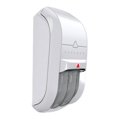
Wireless Outdoor/Indoor Dual Band
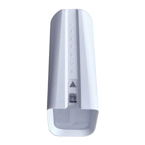
Window and Sliding Door Dual Detector
with Anti-Masking and Pet Immunity
NV35MR-EI04
General Description NV35MR
Thank you for choosing the NV35MR Wireless for your professional
protection needs. The NV35MR wireless Dual Band version will provide you
the most advanced window and sliding doors protection either in Pet
Immune or Sharp mode. If you have any comments please write to us at
Paradox.com/products/feedback.
Pet Recommended Installation (please read)
The NV35MR has been designed to be installed within the frame of
windows and doors when installed outdoors. This will ensure the best
performance against false alarms when random pets such as birds, cats
and small dogs access the window sill. Other installation methods can be
used with the NV35MR such as wall beam protection but if installed
outside of the frame its pet immunity may be compromised.
Installing the NV35MR
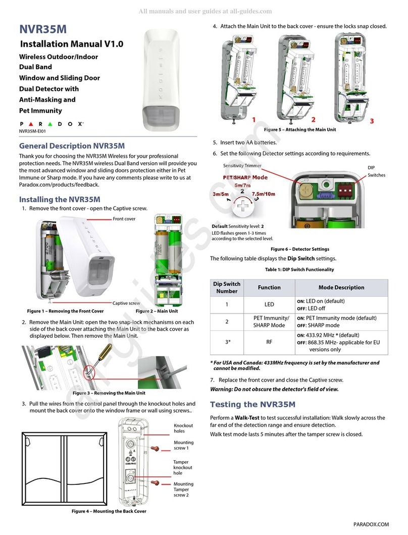
1. Remove the front cover - open the Captive screw.
2. Remove the Main Unit: open the two snap-lock mechanisms on each
side of the back cover attaching the Main Unit to the back cover as
displayed below. Then remove the Main Unit.
3. Mount the back cover of the NV35MR onto the window frame or wall
using screws.
4. Attach the Main Unit to the back cover - ensure the locks snap closed.
5. Insert two AA batteries.
6. Set the following Detector settings according to requirements.
Figure 6 – Detector Settings
The following table displays the Dip Switch settings.
Table 1: DIP Switch Functionality
* For USA and Canada: 433MHz frequency is set by the manufacturer and
cannot be modified.
7. Replace the front cover and close the Captive screw.
Do not obscure the detector's field of view.
Testing the NV35MR
Perform a Walk-Test to test successful installation: Walk slowly across the
far end of the detection range and ensure detection.
Walk test mode lasts 5 minutes after the tamper screw is closed.
Figure 1 – Removing the Front Cover Figure 2 – Main Unit
Figure 3 – Removing the Main Unit
Figure 4 – Mounting the Back Cover
Front cover
Captive screw
Mounting
screw 1
Mounting
Tamper
screw 2
Tamper
knockout
hole
Figure 5 – Attaching the Main Unit
Dip Switch
Number Function Mode Description
1 LED ON: LED on (default)
OFF: LED off
2 PET Immunity/
SHARP Mode
ON: PET Immunity mode (default)
OFF: SHARP mode
3* RF ON: 433.92 MHz * (default)
OFF: 868.35 MHz- applicable for EU
versions only
123
DIP
Switches
Default Sensitivity level: 2
LED flashes green 1-3 times
according to the selected level.
Sensitivity Trimmer
NV35MR
Installation Manual V1.0
