manuals.online logo
Brands
  1. Home
  2. •
  3. Brands
  4. •
  5. Parker
  6. •
  7. Control Unit
  8. •
  9. Parker 71215 User manual

Parker 71215 User manual

-
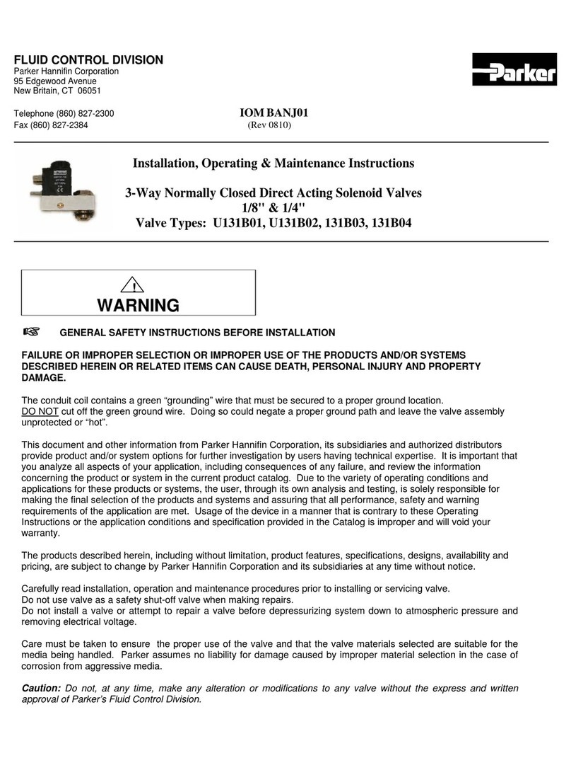
SKINNER VALVE
Parker Hannifin Corporation
95 Edgewood Avenue
New Britain, CT 06051
Telephone (860) 822-2300
-
Climate & lndustrial
Controls
loM7206
Rev(12199)
INSTALLATION, OPERATING & MAINTENANGE INSTRUCTIONS
2-WAY N.C., N.O., AND D. P. SOLENOID VALVE
119,,, 1/4",AND 3lg" NPT
VALVE TYPES: 71215, 71216, 7121V, T1Z}S, 71235 C€
DESCRIPTION
These valves are 2-way, direct operated models. They are
available in normally closed (N.C.), normally open (N.O.), anO
dual purpose (D.p.) versions. The 11215, Z1Zj6, T121V,
71295, and 7123s are offered in stainless steer donstruction.
Valves may be ordered with either NEMA 2,4,4X integrated
coils for ordinary locations or NEMA 4, 4X, 7, and g for
hazardous locations: Divisions I and ll; Class l, Groups A, B,
C, and D; Class ll, Groups E, F, and G. Additional solenoid
coils and enclosures are offered as described in our catalog.
PRINCIPLES OF OPERATION
Normally closed type: 71215
De-energized: Pressure is connected to porl 2 and is
blocked by the plunger seal pressing on the body orifice.
Energized: The plunger is lifted off the orifice allowing flow
through the valvg (Port 2 to 1). On bodies withoul port
markings, the direction of frow is indicated by an arrow on the
body.
Normally closed type: 7121V.
De-energized: Pressure is connected to port 1 and is
blocked by the plunger seal pressing on the body orifice.
Energized: Plunger is lifted off the orifice allowing flow
through valve (Port 1 to 2). On bodies without port maikings,
the direction of flow is indicated by an arrow on the body.
Normally closed, high pressure type: 71216
De-energized: These valves are direct acting, but utilize an
armature, conically shaped pilot, and pilot guide in lieu of a
plunger. Pressure is connected to port 2 and flows up
through the pilot guide, surrounding the armature, where it is
blocked at the orifice by the pilot.
E nergized:. Thearmature -oeelerate-@e
shoulder of the pilot, lifting the pilot off the orifice and allowii!
flow to occur from Porl2 to Port 1.
Normally open type: 7129s
De-energized: Pressure is connected to port 2 and fluid is
free to flow out Port 3.
Energized: The plunger moves causing the seal to block the
normally open orifice. Flow between ports 2 and 3 is then
stopped.
Dual purpose type: 71235
De-energized: Pressure may be connected to either port 1
or Port 2, depending on the desired direction of flow.
Pressure is blocked in either direction by the prunger sear
pressing against the body orifice.
Energized: Plunger is lifted off the orifice allowing flow
through valve. Once again, flow is permitted in either
direction depending upon the supply pressure connection.
FLUID CODES
Listed below are the codes utirized by Underwriters
Laboratories (uL) and the canadian standards Association
(csA) for various common fluids. The codes for those fluids
that are approved or certified by the agencies for use with
each valve are printed on the outside of the individual
packaging.
A
AC
F
(J
GA
HO
- Air or nontoxic, nonflammable gases
- Acetylene
- Common refrigerants except ammonia
- City gas supptied by pubtic utilities
- Gasoline
- Petroleum based hydraulic oils hqving viscosities
of up from 125 to 4OO SSU at 3goC
- Nos. 1 and 2 fuel oils, oils having viscosities not
more than 40 SSU at 3goC
- No. 2 through No. 6 oil
- Oxygen
- Steam
- Water or other aqueous nonflammable liquids
02
02-06
OX
S
W
For the maximum fluid temperatures, as well as valve
ambient limitations, check the varve part number on the
nameplate and refer to the catarog or the outside of the
shipping package.
I NSTALLATION INSTRUCTIONg
Mounting position and pressure limits: Valves can be
mounted directly on piping or by using the two (2) #10-32 NF
threaded holes in the bottom of thJ varve body. Mounting
brackets are avairabre for those varves having #10-32 NF
mounting holes and may be ordered separately.
The7121V,71215,11235, and712gS valves ire designed to
be multi-poised and so wiil perform properry when ,no..i.t"d in
any position. However, for optimum life and performance the
valves should be mounted verticaily upright so as to minimize
wear and reduce the possibility of foreign matter
accumulating inside the sleeve area. The 21216 vllves must
Page 1
Flow Factor ~ 216-765-4231
www.flowfactor.com
always be mounted vertically upright to ensure proper
operation.
Line pressure must conform to nameplate rating.
Piping: Remove protective closures from the ports. Connect
line pressure to the inlet port. Use of Teflon tape, thread
compound or sealants is permissible, but should be applied
sparingly to male pipe threads only. Loctite primer #764 and
pipe sealant #567 are recommended when using stainless
steel fittings with stainless steel valve bodies.
GAUTION: Do not allow foreign particles, Teflon tape, or
thread compound to enter valve. Tightening torque should
not exceed the following values for each port size: 1/8" NPT -
100 in-lbs., 1/4" NPT - 175 in-lbs., 3/8" NPT - 225 inJbs' Do
not use the sleeve or enclosure as a lever when applying
torque.
Media filtration: Normally filtration is not required, but dirt or
foreign material in the media may cause excessive leakage,
wear, or in exceptional cases, malfunction. lf filtration is
used, installthe filter on the inlet side as close to the valvp as
possible. clean periodically depending on service conditions.
Lubrication: Lubrication is not required although air line
lubrication will substantially increase valve. life.
GAUTION: Valves which have sea/s or other components
made trom ethylene propytene rubber must not be exposed to
petroleum based lubricants or other hydrocarbons.
Electrical connection: Electrical supply must conform to
nameplate rating. Connect coil leads or terminals to the
electrical circuit using standard electrical practices in
compliance with local authorities and the National Electrical
Code.
WARNING : Valves t6 be instdllecl in Hdzardous Locationi,
must be outfitted with Hazardous Location coils only. verify
nameplate data and coil part number before installing the
valve.
wARNING: Turn off electrical power before connecting the
valve to the Power source'
lf the coil assembly is located in an inconvenient orientation, it
may be reoriented to facilitate installation. Loosen coil
assembly nut, rotate coil assembly to desired position, then
retighten the nut with an input torque of 43-53 in-lbs'
DIN Goil and Terminal Box Assembly (Goil Code D100,
D200orD300;OptionGodeTB):Loosencoverscrewsan!
swing cover 90o toward the conduit hub in order to access
the interior space. separate the plastic block containing the
screw terminals from the metal enclosure using a small flat
head screwdriver. Feed the lead wires through the conduit
hub and attach them to the appropriate screw terminal. For
-__.- electrical connectiqn within the telmingl !glyq,e- field .wirg
that is rated for 90o C oi gneaten Snap the plastic block back
into place inside the metal enclosure. Replace the cover and
handtighten the cover screws. Place the gasket over the
DIN spldes on the coil and press the terminal box and coil
together.Securetheterminalboxtothecoilusingthe
mountingscrewprovided.App|y20to30in-lbs.torquetothe
mounting screw.
screw Terminal coit and Terminal Box Assembly (Goil
Code S100, 5200, or 5300; Option Code TB): Loosen
cover screws and swing cover 90o toward the conduit hub in
order to access the interior space. Feed the lead wires
through the conduit hub and attach them to the appropriate
screw terminal. For electrical connection within the terminal
box, use field wire that is rated for 90o C or greater' Replace
the cover and hand-tighten the cover screws' Press the
terminal box and coiltogether. secure the terminal box to the
coil using the mounting screw provided' Apply 20 to 30 in-
lbs. torque to the mounting screw.
CAUTIoN: When the DIN or Screw Terminal coils are used
witn ne ferminat Box Assembly, be sure to apply a wrench to
the wrench flats on the conduit hub when installing electrical
conduit.
Goil/enclosure temperature: standard valves are supplied
with coils designed for continuous duty service. Normal free
space must be provided for proper ventilation. when the coil
is energized continuously for long periods of time, the coil
assembly will become hot. The coil is designed to operate
permanently under these conditions. Any excessive heating
will be indicated by smoking and/or odor of burning coil
insulation.
For the maximum valve ambient conditions, as well as the
fluid temperatures, check the valve part number on the
nameplate and refer to the catalog'
MAINTENANCE
Note: Depending on service conditions, fluid being used,
filtration, and lubrication, it may be required to periodically
clean and/or replace worn components. See Disassembly
lnstructions.
CAUTION: Do not expose plastic or elastomeric materials to
mV tVW of commerciat cteaning fluid. Parts should be
cleaned with a mild soap and water solution.
DISASSEM BLY INSTRUCTIONS
WARWI]|O: Depressurize sysfem and turn off electrical
powe@ingrePair.
The N.C. and D.P. valves need not be removed from the line'
lf the pipe connection to N.O. valves is made to the sleeve
port, disconnect piping prior to commencing repair.
To remove the coil assemblY:
Normally Closed and Dual Purpose Valves I For both
ordinary and hazardous location constructions, unscrew the
nut on the top of the coil assembly. The wave washer and
coil assembly can now be removed'
Normally Open Valves - First unscrew the sleeve adapter
and remove. Then follow the same instructions as for
normally closed and dual purpose valves stated above'
To disassemble the pressure vessel:
CAUTION: tf the sleeve assembly does not have a hex style
flange, do not use a pipe wrench directly on the sleeve'
lnstead, use a Skinner LJ99-011 wrench nutto remove and
install the sleeve assemblY.
Normally Glosed, Normally Open, and Dual Purpose
Valves -
Slide the Skinner U99-011 wrench nut over the sleeve tube.
To unscrew the sleeve assembly, mate the wrench nut to the
sleeve flange and turn the wrench nut. The plunger, return
spring, and flange seal may now be removed. The 7121V
valves contain a hex style flange in the sleeve assembly' ln
this case, a wrench may be applied directly to the hex flange
in order to loosen the sleeve assembly.
Manual override removal (where applicable) - Extract the
override retention pin. Rotate override stem until it is free to
Page2
Flow Factor ~ 216-765-4231
www.flowfactor.com
remove. Withdraw override lever, or the spring and roller in
the case of larger size valves (1/8" orifice diameter or
greater).
Replacement Parts: When ordering replacement parts kits,
specify valve number and voltage from nameplate. Parts kits
are available for each valve. Parts included in each kit are
marked with an asterask (.). See exploded views.
REASSEMBLY INSTRUCTIONS
WARNING= When replacing coils, valves equipped with
Hazardous Location coils must use Hazardous Location
replacement coils only. Verify nameplate data and coil pari
number before installing the replacement coil.
To reassemble the pressure vessel:
Refer to exploded view drawings. Parts must be replaced in
the order shown.
Assemble manual override (where available) prior to
assembly of sleeve to body. lnsert override lever into body.
Replace the ovenide stem. Orient stem so that the arrow
stamped on the override is pointing up towards thd sleeve.
lnsert the override retention pin and O-ring into body insuring
that the pin fits into the override stem groove. lnstall the
DECLARATION
Parker's Skinner Valve Division certifies its valve appliance
products complies with the essential requirements of the
applicable European Community Directives. We hereby
confirm that the appliance has been manufactured in
compliance with the applicable standards and is intended for
installation in a machine or application where commissioning
is prohibited until evidence has been provided that the achine
or application is also in compliance with EC directives.
plunger and spring in the sleeve. Tighten sleeve assembly in
the body with an input torque of 130-150 in-lbs (260-270 in-
lbs for 7121V\.
For valves wjth orifice sizes greater than 1/8", place the
spring on the override pin. Assemble roller on the pin.
Carefully insert assembly into valve body. Orient stem so
that the arrow stamped on the override is pointing up
towards the sleeve. lnsert override retention pin and O-ring
into body insuring that the pin fits into the override stem
groove. lnstall the plunger and spring in the sleeve. Tighten
sleeve assembly in the body with an input torque of 130-150
in-lbs (260-270 in-lbs for 7'121Y).
CAUTION: Failure to properly inseft override retention pin
into override stem could allow the override stem to blow out
when valve is pressurized and cause damage.
\Mth coil assembly repositioned on the sleeve, slide the wave
washer over the sleeve and tighten coil assembly nut with an
input torque of 43-53 in-lbs.
Refer to the lnstallation lnstructions for remaining installation
procedures.
The data supplied in the Skinner valve catalogs and general
lnstallation, Operating & Maintenance lnstructions are to be
consulted and pertinent accident prevention regulations
followed during product installation and use. Any
unauthorized work performed on the product by the purchaser
or by third parties can impair its function and relieves Parker
Hannifin of all warranty claims and liability for any misuse and
resulting damage.
A separate Declaration of Conformity or Manufacturer's
declaration is available upon request. Please provide valve
identification numbers and order serial numbers of products
concerned.
1. Check electrical supply with voltmeter. Voltage must
agree with nameplate rating.
2. Check coil with ohmmeter for shorted or open coil.
3. Mark sure that oressure comolies with nameplate ra
Valve fails to operate
1. Disassemble valve as per the Disassembly instructions.
Clean out extraneous matter. The plunger must be free
to move without binding.
2. The plunger spring must not be broken-Replace spring if
Valve is sluggish or inoperative - electrical supply and pressure
check out
External leakage at exhaust adaptor to sleeve joint 1. Check that sleeve is torqued to 130 - 150 in-libs.
(260-270 in-lbs. F or 7 121V).
2. lf leakage persists, remove sleeve and check flange seal
for damaoe. Reolace if defective.
External leakage at exhaust adaptor to sleeve joint 1. Remove sleeve. Rotate override until free to remove.
Check O-ring and the surface it contacts. Clean or
worn or damaoed O-rinq as
External leakage at manual override (where available) 1. Remove sleeve. Rotate override until free to remove.
Check O-ring and the surface it contacts. Clean or
worn or damaqed O-rinq as reouired.
lnternal leakage at body port (N.C. and D.P. valves) or at sleeve
port (N.O. valves). 1. Disassemble valve as per the Disassembly lnstructions.
Remove extraneous matter. Clean parts in mild soap and
water solution.
2. Examine surface of the plunger seal. lf damaged, replace
plunger.
3. lnspect orifice in the body/stop for nicks. Damage may
a new valve or reDlacement parts.
Page 3
Flow Factor ~ 216-765-4231
www.flowfactor.com
twPE 712951
EilCtOsURE
co[.
@ rur
6 arnno
$
@c
\
SCNBY TASE PTATE
trl'CdlDllt Cril,
OUUNENCH '{UT U99.O11
REOT'IRED FOR StEEvE REIIIOVAI
WPES 71215,
71235',71295
OPTUNGER
osPRlilc
n
-t
l-l
sl"EE\rE I I
{}
t
wPE 7121V
OSPRING
OPLUNGER
0
a
b
a
d
I
0
I
g
I
0
fi
€
wPE 71216
oSPRNC
PILOT
AFMATURE
GUIDE
.R.1ryIGE SEAt
VALVE SOOY
Page 4
[Note: All drawings are for representative purposes only.]
VALVE EODY
Flow Factor ~ 216-765-4231
www.flowfactor.com

This manual suits for next models

4

Other Parker Control Unit manuals

Parker 8902/LS User manual

Parker

Parker 8902/LS User manual

Parker CK1-DN User manual

Parker

Parker CK1-DN User manual

Parker S6N-DN User manual

Parker

Parker S6N-DN User manual

Parker Series DFplus User manual

Parker

Parker Series DFplus User manual

Parker CEV-S User manual

Parker

Parker CEV-S User manual

Parker 20K User manual

Parker

Parker 20K User manual

Parker D31DW*EE Series User manual

Parker

Parker D31DW*EE Series User manual

Parker Series DFplus User manual

Parker

Parker Series DFplus User manual

Parker Sporlan LAC-4 Release note

Parker

Parker Sporlan LAC-4 Release note

Parker D1FV EE Series User manual

Parker

Parker D1FV EE Series User manual

Parker DxFB Series User manual

Parker

Parker DxFB Series User manual

Parker DFB Series User manual

Parker

Parker DFB Series User manual

Parker B5 User manual

Parker

Parker B5 User manual

Parker PSSNACM12A Installation and maintenance instructions

Parker

Parker PSSNACM12A Installation and maintenance instructions

Parker S4AD User manual

Parker

Parker S4AD User manual

Parker 7121Z028 Assembly instructions

Parker

Parker 7121Z028 Assembly instructions

Parker R4V Series Wiring diagram

Parker

Parker R4V Series Wiring diagram

Parker PSUP Series User manual

Parker

Parker PSUP Series User manual

Parker MI-101 Operating and maintenance instructions

Parker

Parker MI-101 Operating and maintenance instructions

Parker DN80 User manual

Parker

Parker DN80 User manual

Parker Origa S9 User manual

Parker

Parker Origa S9 User manual

Parker RL Series Technical specifications

Parker

Parker RL Series Technical specifications

Parker EBV-PR Series User guide

Parker

Parker EBV-PR Series User guide

Parker RE06M T Series User manual

Parker

Parker RE06M T Series User manual

Popular Control Unit manuals by other brands

Graco DISPENSIT 1206 instructions

Graco

Graco DISPENSIT 1206 instructions

Niko 10-535-01 manual

Niko

Niko 10-535-01 manual

Nibe ACS 45 Installer manual

Nibe

Nibe ACS 45 Installer manual

powersoft DigiMod IS integration kit Technical note

powersoft

powersoft DigiMod IS integration kit Technical note

GEM 534 Installation, Operating and Maintenance Instruction

GEM

GEM 534 Installation, Operating and Maintenance Instruction

Eaton COOPER POWER SERIES manual

Eaton

Eaton COOPER POWER SERIES manual

Emerson Sempell series operating instructions

Emerson

Emerson Sempell series operating instructions

XEMEX SUNGATE WatchTalk installation manual

XEMEX

XEMEX SUNGATE WatchTalk installation manual

Buderus RC35 Installation and servicing instructions

Buderus

Buderus RC35 Installation and servicing instructions

PDi PD196-244R12 Installation and operating instructions

PDi

PDi PD196-244R12 Installation and operating instructions

Clarion HMML-0034K3 quick start guide

Clarion

Clarion HMML-0034K3 quick start guide

Hubbel CIRCUIT GUARD GFM20 Installation and operating instructions

Hubbel

Hubbel CIRCUIT GUARD GFM20 Installation and operating instructions

Honeywell D05FS installation instructions

Honeywell

Honeywell D05FS installation instructions

Sun Oracle Sun Blade X6275 M2 installation guide

Sun Oracle

Sun Oracle Sun Blade X6275 M2 installation guide

Allen-Bradley 1732ES-IB16 user manual

Allen-Bradley

Allen-Bradley 1732ES-IB16 user manual

GAYLORD RSPC-ESP-OW Series Technical manual

GAYLORD

GAYLORD RSPC-ESP-OW Series Technical manual

Giacomini R314DN manual

Giacomini

Giacomini R314DN manual

WAGO 750-405 manual

WAGO

WAGO 750-405 manual

manuals.online logo
manuals.online logoBrands
  • About & Mission
  • Contact us
  • Privacy Policy
  • Terms and Conditions

Copyright 2025 Manuals.Online. All Rights Reserved.