manuals.online logo
Brands
  1. Home
  2. •
  3. Brands
  4. •
  5. Parker
  6. •
  7. Control Unit
  8. •
  9. Parker CK4A-DN Operating and installation instructions

Parker CK4A-DN Operating and installation instructions

1
Refrigerating Specialties Division
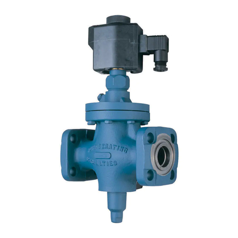
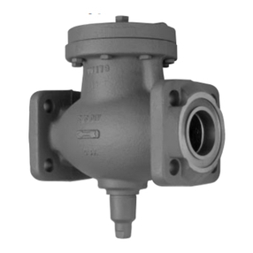
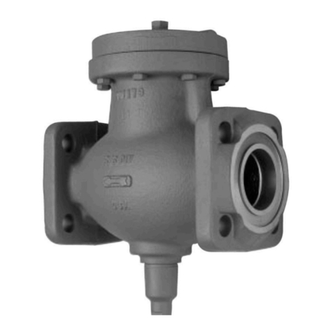
CHECK VALVE
Type CK4A, CK4A-DN
Port Size 13 - 100mm (1/2”- 4”)
FOR AMMONIA, R12, R22, R502
AND OTHER COMMON REFRIGERANTS
FEATURES
• UL Listed (Thru 3" Size)
• Installs in any position
• Compact
• Lightweight
• In-Line
• Design Pressure (PS): 34.5 bar (500 psi)
•ComplieswithPressureEquipmentDirective97/23/EC
BULLETIN 50-16
Type CK4A-DN
February,2002
Installation and Service Information
ISO 9001 CERTIFIED
Description
These compact valves are spring closing with a lapped,
stainless steel or chrome plated seat for positive closing
action and low leakage. A minimum pressure difference of
0.05 bar (0.75 psi) is required to hold the valve in the open
position. Removable seat plate with combination O-ring and
metal-to-metal knife edge seal allows the valve to be
disassembled for maintenance. They may be ordered with
male adapter rings for close-coupling to other Refrigerating
Specialties valves and may be installed in any position.
Purpose
The Type CK4A Check Valves prevent backward flow of fluid
inrefrigerant suction,hot gasor liquid lines.Themostfrequent
use for these valves is in recirculating (overfeed) systems.
They are especially suited for high speed compressor
discharge, pump discharge, suction - down to -50°C (-60°F)
and hot gas lines (pan to evaporator).
Certain refrigerant flows pulsate sufficiently or with a
frequency in harmony with the valve’s natural frequency,
which can cause “slapping” or even wholesale failure.These
valves are not recommended for slow speed compressor
discharge lines (See CK-1, Bulletin DN50-10) or for any
compressor discharge where a low speed machine
discharges into the same downstream header, or for use on
side-port suction lines on a screw compressor installation.
Operation
These are light spring-closing check valves. An increase in
the pressure drop across the valve overcomes the force of
the closing spring and the disc is forced away from its seat
permitting flow. As the flow decreases, the disc is forced
back against its seat by the expansion of the closing spring.
Flow is then stopped.
Installation
Keep dirt from entering the valve. Do not remove protective
packaging until ready to install.
Install the valve where it can be serviced easily. DO NOT
INSTALL AT THE INLET OF A SOLENOID VALVE, OR A
REGULATORWITHAN ELECTRICSHUT-OFFFEATURE;DO
NOT INSTALL AT THE INLET OF AN OUTLET PRESSURE
REGULATOR IN A SYSTEM WHERE LIQUID MAY BE
TRAPPEDBETWEENTWOVALVES.CheckValveswhenused
with such valves should always be installed at the outlet of
the valves.
NOTE:THE ODSCOPPER FLANGESAVAILABLEARE ONLY
FOR INSTALLATIONS WHERE R-12, R-22, AND R-502 OR
OTHER HALOCARBON REFRIGERANTS ARE USED. DO
NOT USE THESE FLANGES FOR AMMONIA. FOR
INSTALLATIONSUSING AMMONIATHE FPT, SOCKETWELD
ORWELDNECK FLANGESSHOULD BEUSED.
The Type CK4A Valves may be installed in any position. The
valve must be installed with the arrow pointing in the direction
of flow.After installing the valve, tighten the flange bolts evenly.
The CK4A Check Valves may be closed-coupled to
Refrigerating Specialties Refrigerant Valves and most hand
valves by using a Refrigerating Specialties Male Adapter Ring.
Fig. 1
310230
32 bar (460 psi)
• Complies with Pressure Equipment Directive 97/23/EC
DN 32-100 32 bar (460 psi)
• Design Pressure (PS): DN 13-25 34.5 bar (500 psi)
Refrigerating Specialties Division 2
PORT SIZE
Dimension 13mm 20-25mm 32mm 50mm 65mm 75mm 100m
(1/2”) (3/4 - 1”) (1-1/4”) (2”) (2-1/2”) (3”) (4”)
Amm 75 113 95 114 148 148 179
inch 29.3 4.43 3.75 4.50 5.81 5.81 7.06
Bmm 38 62 95 114 148 148 179
inch 1.50 2.43 3.75 4.50 5.81 5.81 7.06
Cmm 27 32 50 60 70 81 89
inch 1.06 1.25 2 2.37 2.75 3.19 3.50
D mm 63 59 79 114 145 157 177
(FPT, SW) inch 2.47 2.32 3.10 4.47 5.72 6.16 6.97
Conn.
Size 3/8, 1/2, 3/4 3/4” 1” 1-1/4” 1-1/4” 1-1/2” 1-1/2” 2” 2-1/2” 3” 4”
Emm 82 97 117 117 126 136 171 177 215 245 298
inch 3.22 3.82 4.61 4.61 4.97 5.35 6.72 6.97 8.47 9.66 11.72
Conn.
Size 1/2 5/8 7/8 7/8 1-1/8 1-3/8 1-5/8 1-3/8 1-5/8 2-1/8 1-5/8 2-1/8 2-5/8 2-5/8 3-1/8 3-1/8 3-5/8 4-1/8
Fmm 76 82 98 99 193 99.5 111 119 130 159 193 177 205 203 250 228 248 285
inch 2.98 3.22 3.85 3.88 4.07 3.91 4.36 4.69 5.12 6.26 7.57 6.95 8.08 7.98 9.82 8.95 9.76 11.2
Nmm913292024252825283428343737424248 55
inch .37 .50 .75 .75 .93 .96 1.09 .96 1.09 1.34 1.09 1.34 1.46 1.46 1.65 1.65 1.90 2.15
Pmm 13 13 15 15 25 29 32
inch .50 .50 .60 .60 1.0 1.1 1.3
Dimensional Data
CK4A 1-1/4" TO 4"
PRESSURE BEARING COMPONENTS
COMPONENT DESCRIPTION MATERIAL
CASTING,BODY 1-1/4 CK4A DN DUCTILE IRON GGG 40.3
SEAT,VALVE 1-1/4, 2-1/2 & 3" CK4A BAR,RD 2.687 STL 1213
SEAT,VALVE 2 CK4A 3-3/8" DIA. 1215 C.D.S./ HARD CHROME PLATE
SEAT,VALVE 4 CK4A TUBE,RD 6.00 OD X 3.00 ID STL
DISC,VALVE CK4A- 6 1-1/4 ASTM A240 304 STAINLESS STEEL
DISC,VALVE 2 TO " CK4A BAR,RD 2.250 SS 303
DISC,VALVE CK4A- 16 BAR,RD 4.000 SS 303
STEM,VALVE 2 CK4A BAR,RD .250 SS 303
STEM,VALVE 2-1/2 CK4A BAR,RD .312 SS 303
STEM,VALVE 3 & 4" CK4A BAR,RD .375 SS 303
ITEM DESCRIPTION
4 Gasket, Flange
6 Valve Seat
7O-Ring
8 Disc Asm.
9 Spring, Comp
For replacement parts and prices, consult
PARTS KITS LIST PRICE SCHEDULE INDUSTRIAL AND FLO-CON (PK)
3
Refrigerating Specialties Division
Type CK4 – 1/2" thru 1-1/4"
Type CK4 – 2" thru 4"
P
A
C
D
B
4
Parker Hannifin Corporation • Refrigerating Specialties Division
2445 South 25th Avenue • Broadview, IL 60155-3891 USA
Telephone: (708) 681-6300 • Fax (708) 681-6306
Service
Dirt or other foreign material in the system is the greatest
single cause of valve malfunction.
Before disassembling a check valve for servicing, read and
become familiar with the Safe Operation Instructions in this
bulletin as well as in the current issue of Safety Bulletin RSB.
Check the following chart for possible symptoms and
corrections.
Symptom Probable Reason Correction
Valve does not Dirt or chips Disassemble valve
close or there under valve seat. and clean
is leakage thoroughly.
through valve. Replace any
damaged parts.
Valve chatters. Valve is Replace with
oversized. smaller port size or
use Type CK-1.
Disassembly
Caution - If the valve to be disassembled or removed is
close-coupled to a solenoid operated valve make sure that
the power supply to the valve is de-energized and all
refrigerant is pumped out of the line. Refer to Page 3 as
necessary.After removing the valve from between the flanges
remove the parts in the numerical order shown in the
applicable exploded view. In all CK4A Valves the seat plates
with the O-rings are removed by gently tapping out the seat
from the opposite end of the valve body.Use a wooden dowel
for this purpose.
Assembly
Before assembling all parts must be clean, dry and lightly
coated with refrigerant oil. If an existing valve or strainer is
close-coupled to the check valve, either one should be
opened, inspected and cleaned before putting it and the
check valve back in service.
Refer to Page 3 as applicable. Assemble the valve in the
reverse numerical order shown in the exploded view. Make
sure the O-ring is firmly seated and permanently retained by
the seat plate when reassembled.
Warranty
All Refrigerating Specialties products are warranted against
defects in workmanship and materials for a period of one
year from date of shipment from originating factory. This
warranty is in force only when products are properly installed,
field assembled, maintained, and operated in use and service
as specifically stated in Refrigerating Specialties Catalogs
or Bulletins for normal refrigeration applications, unless
otherwise approved in writing by Refrigerating Specialties
Division. Defective products, or parts thereof returned to the
factory with transportation charges prepaid and found to be
defective by factory inspection will be replaced or repaired
at Refrigerating Specialties option, free of charge, F.O.B.
factory. Warranty does not cover products which have been
altered, or repaired in the field; damaged in transit, or have
suffered accidents, misuse, or abuse. Products disabled by
dirt or other foreign substances will not be considered
defective.
THE EXPRESS WARRANTY SET FORTH ABOVE
CONSTITUTES THE ONLY WARRANTY APPLICABLE TO
REFRIGERATINGSPECIALTIES PRODUCTS,ANDISIN LIEU
OF ALL OTHER WARRANTIES, EXPRESSED OR IMPLIED,
WRITTEN OR ORAL, INCLUDING ANY WARRANTY OF
MERCHANTABILITY, OR FITNESS FOR A PARTICULAR
PURPOSE. No employee, agent, dealer or other person is
authorized to give any warranties on behalf of Refrigerating
Specialties, nor to assume, for Refrigerating Specialties, any
other liability in connection with any of its products.
Safe Operation (See also Bulletin RSBCV)
People doing any work on a refrigeration system must be
qualified and completely familiar with the system and the
Refrigerating Specialties Division valves involved, or all other
precautions will be meaningless. This includes reading and
understanding pertinent Refrigerating Specialties Division
product Bulletins, and Safety Bulletin RSBCV prior to
installation or servicing work.
Where cold refrigerant liquid lines are used, it is necessary
that certain precautions be taken to avoid damage which
could result from liquid expansion. Temperature increase in
a piping section full of solid liquid will cause high pressure
due to the expanding liquid which can possibly rupture a
gasket, pipe or valve. All hand valves isolating such sections
should be marked, warning against accidental closing, and
must not be closed until the liquid is removed. Check valves
must never be installed upstream of solenoid valves, or
regulators with electric shut-off, nor should hand valves
upstream of solenoid valves or downstream of check valves
be closed until the liquid has been removed. It is advisable
to properly install relief devices in any section where liquid
expansion could take place.
Avoid all piping or control arrangements which might produce
thermal or pressure shock.
For the protection of people and products, all refrigerant must
be removed from the section to be worked on before a valve,
strainer, or other device is opened or removed.
Flanges with ODS connections are not suitable for ammonia
service.
This manual suits for next models

1

Other Parker Control Unit manuals

Parker CK-6D User manual

Parker

Parker CK-6D User manual

Parker TPQ Series User manual

Parker

Parker TPQ Series User manual

Parker AC30V Series User manual

Parker

Parker AC30V Series User manual

Parker Sporlan B5D Series User guide

Parker

Parker Sporlan B5D Series User guide

Parker 60VM4071 User manual

Parker

Parker 60VM4071 User manual

Parker EP Series Pro-Bloc User manual

Parker

Parker EP Series Pro-Bloc User manual

Parker TDC Series User manual

Parker

Parker TDC Series User manual

Parker P33 Quick setup guide

Parker

Parker P33 Quick setup guide

Parker PACHC Series User manual

Parker

Parker PACHC Series User manual

Parker D 1FC Series User manual

Parker

Parker D 1FC Series User manual

Parker D Series User manual

Parker

Parker D Series User manual

Parker U Series Technical specifications

Parker

Parker U Series Technical specifications

Parker SC Series Reference manual

Parker

Parker SC Series Reference manual

Parker IQAN-LC5-C02 User manual

Parker

Parker IQAN-LC5-C02 User manual

Parker EBV-PR Series User guide

Parker

Parker EBV-PR Series User guide

Parker 930 Series Guide

Parker

Parker 930 Series Guide

Parker U131B01 Assembly instructions

Parker

Parker U131B01 Assembly instructions

Parker S5A Guide

Parker

Parker S5A Guide

Parker D31FBxEE Series User manual

Parker

Parker D31FBxEE Series User manual

Parker S7A Service manual

Parker

Parker S7A Service manual

Parker 71215 User manual

Parker

Parker 71215 User manual

Parker CW Series Operating instructions

Parker

Parker CW Series Operating instructions

Parker S4AD User manual

Parker

Parker S4AD User manual

Parker Series DFplus User manual

Parker

Parker Series DFplus User manual

Popular Control Unit manuals by other brands

Burkert 2300 Series quick start

Burkert

Burkert 2300 Series quick start

GEA Aseptomag GD Operating	 instruction

GEA

GEA Aseptomag GD Operating instruction

Woodward easYgen-3000 manual

Woodward

Woodward easYgen-3000 manual

Sony LLC-8000A Service manual

Sony

Sony LLC-8000A Service manual

beier AKL-8-W Operation manual

beier

beier AKL-8-W Operation manual

Burkert 0258 operating instructions

Burkert

Burkert 0258 operating instructions

Honeywell HS10S installation instructions

Honeywell

Honeywell HS10S installation instructions

Piratelogic EVE Construction manual

Piratelogic

Piratelogic EVE Construction manual

Solinst 464 Mk3 250 psi Replacement

Solinst

Solinst 464 Mk3 250 psi Replacement

WAGO 751-5202 manual

WAGO

WAGO 751-5202 manual

Texas Instruments TDC7200EVM user guide

Texas Instruments

Texas Instruments TDC7200EVM user guide

Barth Mini-PLC STG-850 manual

Barth

Barth Mini-PLC STG-850 manual

RTS 4010 user manual

RTS

RTS 4010 user manual

Siemens SINUMERIK 840D sl Commissioning manual

Siemens

Siemens SINUMERIK 840D sl Commissioning manual

Lutz-Jesco C 7523 operating instructions

Lutz-Jesco

Lutz-Jesco C 7523 operating instructions

Blue Point Engineering DMX Analyzer manual

Blue Point Engineering

Blue Point Engineering DMX Analyzer manual

Anilam 5000M CNC manual

Anilam

Anilam 5000M CNC manual

Festo CPX-FVDA-P2 Original instructions

Festo

Festo CPX-FVDA-P2 Original instructions

manuals.online logo
manuals.online logoBrands
  • About & Mission
  • Contact us
  • Privacy Policy
  • Terms and Conditions

Copyright 2025 Manuals.Online. All Rights Reserved.