3
Refrigerating Specialties Division
turn the adjusting stem in (clockwise) until the pres-
sure gauge shows a slight rise in the inlet pressure.
At this point the adjusting stem may be turned in to
raise the pressure further, or backed out to lower it:
but the final adjustment should be made after the
system has been operating for a period of time. This
setting, without air pressure to the bonnet, represents
the lowest inlet pressure the regulator will allow, thus
providing a low limit feature. Connect the air line.
From this point, the inlet pressure will be increased 1
psi for every 1 psi pressure increase the controller
applies to the top of the diaphragm (A4AP). In the
case of the A4A3P, the inlet pressure will be in-
creased 3 psi for every 1 psi pressure increase the
controller applies to the top of the diaphragm. The
A4A3P is available in Range A and V only. The
A4AP is available in Range A, V and D.
Installation
All regulators are packed for maximum protection.
Unpack carefully, check the carton to make sure all
flanges and other items are unpacked. Save the
enclosed instructions for the installer and eventual
user.
Do not remove the protective coverings from the inlet
and outlet of the regulator until the regulator is ready
to be installed. Protect the inside of the regulator
from moisture, dirt and chips before and during
installation. When welded or brazed flange connec-
tions are used, all slag, scale and loose particles
should be removed from the flange interior before the
regulator is installed between the flanges. It is
advisable to install a close-coupled companion
strainer (RSF) at the inlet of the regulator to help
protect it from any foreign material in the system.
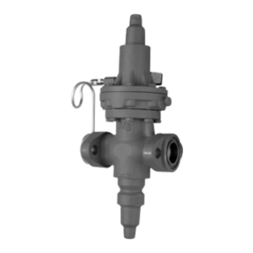
The A4A series of regulators will give optimum
performance if mounted in a horizontal line in a
vertical position with the manual opening stem on
bottom. Where other positions are desired, the
factory should be consulted: please give application
and piping details. The regulator must be installed
with the arrow on the valve body pointing in the
direction of the fluid flow for the regulator to function
properly. Backward flow through the regulator is
uncontrolled and will vary with valve model and the
reverse pressure drop encountered. The regulator is
not a check valve.
Tighten the flange bolts and nuts evenly to provide
proper seating of the flange gasket and to avoid
damage to gaskets or flanges. (See Bolt Torque
Table). Avoid using the regulator flange bolts to
stretch or align pipe. Even the heavy duty body of an
A4A can be distorted, causing the precision parts to
bind.
The regulator should be installed in a location where it
is easily accessible for adjustment and maintenance.
The location should be such that the regulator can not
be easily damaged by material handling equipment.
When it is necessary to insulate the regulator (and
companion strainer), the insulation should be installed
to provide access to the regulator (and companion
strainer) for adjustment and maintenance. Do not
insulate the solenoid coil and coil housing. Proper
indicating gauges should be installed to be easily
visible to the operating engineer for system checking
and adjusting purposes.
Disassembly and Assembly
Before disassembling any A4A type regulator, read
the information in this bulletin and Bulletin RSBCV,
SafetyProceduresforRefrigeratingSpecialties
DivisionRefrigerationControlValves.
Before a regulator is removed from the line or disas-
sembled in the line, make sure that all refrigerant has
been removed from the regulator, including the
bonnet, where applicable, and the close-coupled
strainer. The regulator must be isolated from the rest
of the system in a safe manner. When pumping
down to remove the refrigerant, the manual opening
stem 33A must be turned out (counter clockwise) to
make sure the valve is open.
All A4A Regulators
General Procedure
The construction of the regulator and the method of
disassembly are relatively simple, but some proce-
dures must be followed to avoid damage. The
following describes the procedure for the basic A4A .
Disassembly - Take care when removing Seal Caps
1 and 44 in case some refrigerant may be trapped
inside. Back the Adjusting Stem 6 all the way out to
remove any compression on Range Spring 13
otherwise damage to Diaphragm 17 or Pilot Seat 18
may occur. Disconnect air lines before removing
bonnet. Remove Bonnet 8 by carefully removing Cap
Screws 11. Take care not to damage Diaphragm
Follower 15. Remove Adapter 28 by removing Cap
Screws 31. Turn the Manual Opening Stem 33A all
the way in until the flats on the stem barely protrude
from the stuffing box nut. Push Piston 30 down
against the spring force. The piston should move
freely down and be returned by the spring force. If
the piston is jammed or sticky, remove Bottom Cap
Assembly, which includes Items 33 through 42, by
removing Cap Screws 39 or unscrewing Bottom Cap,
3/4" through 1-1/4" (20mm through 32mm). Using a
hard wood dowel rod inserted through the bottom of
the valve, tap the piston upward and out. Thoroughly
clean all parts. If jamming has taken place and the
piston and bore are scored, remove all burrs by
