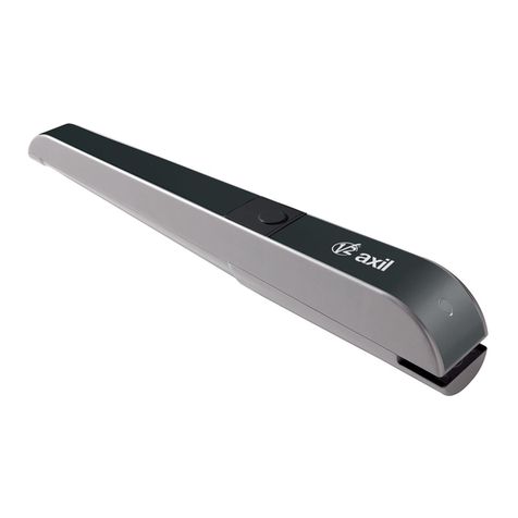
V2 JEDI-L User manual

IL n. 321
EDIZ. 22/06/2010
EDI-L
ATTUATORE ELETTROMECCANICO
PER PORTE SEZIONALI E BASCULANTI
ELECTROMECHANICAL ACTUATOR FOR SPRING
AND COUNTERWEIGHT BALANCED DOORS
OPERATEUR ELECTROMECANIQUE POUR PORTES
SECTIONNELLES ET BASCULANTES
MOTOR DE TECHO ELECTROMECÁNICO
PARA PUERTAS SECCIONALES Y BASCULANTES
MOTORREDUTOR ELECTROMECÂNICO PARA
PORTAS SECCIONADAS E BASCULANTES
ELEKTROMECHANISCHER STELLANTRIEB FÜR
SEKTIONALTORE UND SCHWINGTORE
ELEKTROMECHANISCHE GARAGEPOORTOPENER
VOOR SECTIONAALPOORTEN EN KANTELPOORTEN
I
GB
F
E
P
D
NL


ITALIANO
1
DATI TECNICI
EDI-L
Alimentazione 230Vac - 50Hz
Potenza assorbita max. 160W
Carico max. accessori 12W
Fusibile di protezione SOURCE = 2,5A
Superficie porta < 15m2
Velocità media 110mm/s
Forza di spunto 1000N
Forza nominale 850N
Temperatura di lavoro -20 ÷ +40 °C
Tempo di funzionamento continuo > 4 min.
rado di protezione IP20
Peso 12Kg
INDICE
CONFORMITÁALLENORMATIVE.......................1
DATITECNICI .....................................1
AVVERTENZE IMPORTANTI PER L’INSTALLATORE . . . . . . . . . . .2
VERIFICHEPRELIMINARI .............................3
SCHEMADIINSTALLAZIONE ..........................3
MONTA IO DEL PROFILATO UIDA . . . . . . . . . . . . . . . . . . .4
MONTA IO DEL MOTORE SUL PROFILATO . . . . . . . . . . . . . .5
INSTALLAZIONE....................................5
SBLOCCO DELL’AUTOMAZIONE . . . . . . . . . . . . . . . . . . . . . . .6
COLLE AMENTIELETTRICI ...........................6
IMPOSTAZIONE DEI PARAMETRI DI FUNZIONAMENTO . . . . . . .7
MEMORIZZAZIONE DEI TELECOMANDI . . . . . . . . . . . . . . . . . .10
CANCELLAZIONE DEI TELECOMANDI . . . . . . . . . . . . . . . . . . .10
DICHIARAZIONE DI INCORPORAZIONE PER LE
QUASI MACCHINE (Direttiva 2006/42/CE, Allegato II-B)
Il fabbricante V2 S.p.A., con sede in
Corso Principi di Piemonte 65, 12035, Racconigi (CN), Italia
Dichiara sotto la propria responsabilità che:
l’automatismo modello:
EDI-L
Matricola e anno di costruzione: posti sulla targa dati
Descrizione: Attuatore elettromeccanico per porte di garage
• è destinato ad essere incorporato in una porta di garage
per costituire una macchina ai sensi della Direttiva 2006/42/CE.
Tale macchina non potrà essere messa in servizio prima di
essere dichiarata conforme alle disposizioni della direttiva
2006/42/CE (Allegato II-A)
• è conforme ai requisiti essenziali applicabili delle Direttive:
Direttiva Macchine 2006/42/CE (Allegato I, Capitolo 1)
Direttiva bassa tensione 2006/95/CE
Direttiva compatibilità elettromagnetica 2004/108/CE
Direttiva Radio 99/05/CE
La documentazione tecnica è a disposizione dell’autorità competente
su motivata richiesta presso:
V2 S.p.A., Corso Principi di Piemonte 65,
12035, Racconigi (CN), Italia
La persona autorizzata a firmare la presente dichiarazione di
incorporazione e a fornire la documentazione tecnica:
Cosimo De Falco
Rappresentante legale di V2 S.p.A.
Racconigi, il 11/01/2010

ITALIANO
2
AVVERTENZE IMPORTANTI
Per chiarimenti tecnici o problemi di installazione la V2 S.p.A.
dispone di un servizio di assistenza clienti attivo durante le ore di
ufficio TEL. (+39) 01 72 81 24 11
V2 S.p.A. si riserva il diritto di apportare eventuali
modifiche al prodotto senza preavviso; inoltre declina ogni
responsabilità per danni a persone o cose dovuti ad un uso
improprio o ad un’errata installazione.
LEGGERE ATTENTAMENTE IL SEGUENTE MANUALE DI
ISTRUZIONI PRIMA DI PROCEDERE CON L'INSTALLAZIONE.
• Il presente manuale di istruzioni è destinato solamente a
personale tecnico qualificato nel campo delle installazioni di
automazioni.
•Nessuna delle informazioni contenute all'interno del manuale
può essere interessante o utile per l'utilizzatore finale.
• Qualsiasi operazione di manutenzione o di programmazione
deve essere eseguita esclusivamente da personale
qualificato.
L’AUTOMAZIONE DEVE ESSERE REALIZZATA IN
CONFORMITÀ ALLE VIGENTI NORMATIVE EUROPEE:
EN 60204–1 (Sicurezza del macchinario, equipaggiamento
elettrico delle macchine, parte 1: regole generali).
EN 12445 (Sicurezza nell'uso di chiusure automatizzate,
metodi di prova).
EN 12453 (Sicurezza nell'uso di chiusure automatizzate,
requisiti).
• L'installatore deve provvedere all'installazione di un
dispositivo (es. interruttore magnetotermico omologato) che
assicuri il sezionamento onnipolare del sistema dalla rete di
alimentazione. La normativa richiede una separazione dei
contatti di almeno 3 mm in ciascun polo (EN 60335-1).
• L’installazione richiede competenze in campo elettrico e
meccanico; deve essere eseguita solamente da personale
qualificato in grado di rilasciare la dichiarazione di conformità
di tipo A sull’installazione completa (Direttiva macchine
98/37/EEC, allegato IIA).
• E’ obbligo attenersi alle seguenti norme per chiusure
veicolari automatizzate: EN 12453, EN 12445, EN 12978 ed
alle eventuali prescrizioni nazionali.
• Anche l’impianto elettrico a monte dell’automazione deve
rispondere alle vigenti normative ed essere eseguito a regola
d’arte. V2 S.p.A. non si assume nessuna
responsabilità nel caso in cui l’impianto a monte non
risponda alle vigenti normative e sia eseguito a regola d’arte.
• La regolazione della forza di spinta della porta deve essere
misurata con apposito strumento e regolata in accordo ai
valori massimi ammessi dalla normativa EN 12453.
• È vietato l’utilizzo di JEDI-L in ambienti polverosi e
atmosfere saline o esplosive.
• L’operatore è realizzato soltanto per il funzionamento in locali
asciutti.
• Per salvaguardare l’incolumità delle persone è d’importanza
vitale rispettare tutte le istruzioni
• Conservare con cura questo manuale di istruzioni
• Non permettere ai bambini di giocare con la porta motorizzata.
Tenere il trasmettitore lontano dalla portata dei bambini!
• Mettere in funzione la porta solo quando tutta l’area è in
vista. Assicurarsi che la zona di movimento della porta,
potenzialmente pericolosa, sia sgombra di ostacoli o persone.
• Non utilizzare l’operatore dopo aver riscontrato la necessità di
riparazioni o lavori di regolazione, perché un guasto
dell’impianto o una porta sbilanciata possono causare lesioni.
• Informare tutte le persone che utilizzano la porta motorizzata
sulle modalità di comando corrette ed affidabili.
Dimostrare e provare la funzione d’inversione del moto
(in presenza di ostacolo alto 50 mm e forza max. 150 N)
nonché lo sblocco meccanico.
• Per salvaguardare cose e persone, prima di concludere la
messa in servizio si deve eseguire un controllo di sicurezza, al
fine di garantire che l’operatore disinserisca ed inverta il moto
in presenza di un ostacolo (forza max. 150 N, corrisponde a
ca. 15 kg, al di sopra di una luce di 50 mm), in conformità
alla normativa in vigore (EN 12453).
• Tale prova e misurazione sulla forza può essere eseguita solo
da personale specializzato. Rilevando un ostacolo la porta
dovrà arrestare ed invertire il moto (completamente o anche
solo parzialmente, secondo le impostazioni effettuate sulla
logica di comando).
Se la porta non scorre sulla corsa richiesta o se non inverte il
moto rilevando un ostacolo, bisognerà ripetere la regolazione
della forza e corsa. Successivamente ripetere la prova.
Se anche dopo le correzioni effettuate la porta non arresta e
non inverte il modo come invece richiesto dalla normativa,
non potrà continuare a funzionare automaticamente.
• Verificare regolarmente che la porta inverta in presenza di un
ostacolo alto 40 mm.
• Controllare frequentemente l’installazione, in particolare cavi,
molle e parti meccaniche per segni di usura, danneggiamento
o sbilanciamento.
• La spina deve essere facilmente raggiungibile dopo
l’installazione
• I dati di targa del prodotto sono riportati sull’etichetta
applicata in prossimità della morsettiera per i collegamenti
• Eventuali apparecchiature accessorie applicate in postazione
fissa (quali pulsanti e simili), devono essere installate nel
campo visivo della porta ad un’altezza di almeno 1,5m da
terra. Montare gli accessori assolutamente lontano dalla
portata dei bambini!
• La segnaletica relativa ai pericoli residui quali lo
schiacciamento, deve essere affissa su un punto ben visibile o
in prossimità del pulsante in postazione fissa.

ITALIANO
3
VERIFICHE PRELIMINARI
Prima di procedere con l’installazione di JEDI-L è fondamentale
verificare i seguenti punti:
• Verificare che la porta possa essere automatizzabile
(verificare la documentazione della porta). Inoltre verificare
che la struttura della stessa sia solida e adatta ad essere
automatizzata.
• Eseguire il fissaggio del motore in modo stabile utilizzando
materiali adeguati.
• Effettuare se necessario, il calcolo strutturale e allegarlo al
fascicolo tecnico.
• Verificare che la porta sia dotata di sistemi anticaduta
(indipendenti dal sistema di sospensione).
• Verificare che la porta sia funzionale e sicura.
• La porta si deve aprire e chiudere liberamente senza nessun
punto di attrito.
• La porta deve essere adeguatamente bilanciata sia prima
che dopo l'automatizzazione: fermando la porta in
qualsiaisi posizione non deve muoversi; eventualmente
provvedere ad una regolazione delle molle o dei contrappesi.
•È consigliabile installare il motoriduttore in corrispondenza
del centro della porta, al massimo è consentito lo
scostamento laterale di 100 mm necessario per installare
l’archetto accessorio 162504 (vedi paragrafo 3 pag.6) .
• Nel caso in cui la porta sia basculante verificare che la
distanza minima tra il binario e la porta non sia inferiore
a 20 mm.
SCHEMA DI INSTALLAZIONE
Fotocellule cavo 4 x 0,5 mm2(RX)
cavo 2 x 0,5 mm2(TX)
Pulsantiera interna cavo 3 x 0,5 mm2
Presa Schuco -
Scatola di derivazione -
Attuatore JEDI-L cavo con spina 2 x 0.75 mm2
Lampeggiante cavo 2 x 0.5 mm2
Antenna cavo R -58
Selettore a chiave cavo 3 x 0.5 mm2

ITALIANO
4
MONTAGGIO DEL PROFILATO
GUIDA
1. Estrarre il profilato dall’imballo di
cartone e verificarne l’integrità.
2. Aprire il profilato come indicato nella
figura che segue.
3.Una volta disteso il profilato far scorrere
il profilato di giunzione Rfino alla
posizione limite evidenziata dai due fori
Qsul profilato guidacatena.
4. Regolare la tensione della catena agendo
sulla vite a testa esagonale con una
chiave da 10 mm: avvitare il dado fino a
quando la catena rimane
sufficientemente tesa.
ATTENZIONE: assicurarsi che il
carrello di traino scorra liberamente in
tutta la lunghezza della guida.
Eliminare eventuali attriti prima di
procedere con le seguenti fasi di
montaggio.

ITALIANO
5
MONTAGGIO DEL MOTORE SUL
PROFILATO
1. Inserire l’adattatore albero/pignone sull’albero del
motore.
2. Posizionare il profilato Asul motore: l’adattatore
albero/pignone Bdeve innestarsi nell’apposita sede sul
profilato. Verificare che il profilato vada in battuta sul
motore.
3. Posizionare le due staffe omega Csul profilato in
corrispondenza dei fori sulla base del motore.
4.Fissare le due staffe omega con le viti autofilettanti
6 x 15 in dotazione D.
In caso di problemi di spazio, il motore può
essere montato ruotato di 90°.
INSTALLAZIONE
2.1 Smontare il sistema di chiusura della porta.
2.2 Misurare l'esatta metà della porta e tracciare dei
punti di riferimento sulla traversa superiore e sul
soffitto per facilitare il posizionamento del profilato
guida.
2.3 Ancorare la staffa Ealla traversa superiore della
porta con dei tasselli Gadatti al tipo di parete
(ø minimo 8 mm).
2.4 Agganciare il profilato Aalla staffa utilizzando
la vite Fa testa esagonale 6x80 in dotazione con il
relativo dado autobloccante.
2.5 Piegare le 2 barre forate alla lunghezza desiderata
2.6 Fissare la barra forata anteriore Halla staffa di
fissaggio Iinserita nel profilato, utilizzando le viti
L8x20 con i relativi dadi
2.7 Fissare la barra forata posteriore Malla staffa
omega N, utilizzando le viti L8x20 con i relativi dadi
2.8 Seguendo i riferimenti precedentemente tracciati sul
soffitto individuare i punti di fissaggio per barre H
eM; forare e utilizzando dei tasselli Oadatti al tipo
di soffitto (ø minimo 8 mm) ancorare l'automazione.

ITALIANO
2.9 Solo per porte sezionali e basculanti a molle
Fissare la piastra di traino Isulla parte superiore
della porta rispettando i riferimenti precedentemente
tracciati. Unire la barra forata Le il braccio curvo M
utilizzando 2 bulloni 6x15. Unire il braccio curvo Me la
piastra di traino Iutilizzando il perno con testa cilindrica
con l’apposita coppiglia.
3 Solo per porte basculanti a contrappesi
Fissare il braccio ad archetto 162504 sulla parte superiore
della porta seguendo i riferimenti precedentemente
tracciati.
Le due piastre di ancoraggio (inferiore e superiore)
dell’archetto 162504 devono essere sullo stesso piano, in
caso contrario aggiungere degli spessori.
Collegare la barra forata Lalla barra forata del braccio
ad archetto utilizzando 2 bulloni 6x15.
SBLOCCO DELL’AUTOMAZIONE
Per sbloccare l'automazione dall’interno è sufficiente tirare il
pomello verso il basso.
ATTENZIONE: non usare il pomello per aprire la porta.
È vietato appendere oggetti al cordino di sblocco.
Per sbloccare l’automazione dall’esterno installare il kit di sblocco
accessorio codice 162518.
COLLEGAMENTI ELETTRICI
La centrale di comando all’interno di JEDI-L è già cablata.
E’ sufficiente inserire la spina nella presa di corrente per procedere
con la programmazione dei parametri di funzionamento.
Per il collegamento degli accessori far riferimento allo schema che
segue:
6

ITALIANO
7
IMPOSTAZIONE DEI PARAMETRI DI
FUNZIONAMENTO
JEDI-L è equipaggiato con una pratica interfaccia
che consente una rapida e semplice
programmazione tramite il display e i quattro tasti
, , +,-.
Operazioni preliminari:
1. Muovere la porta fino ad agganciare il carrello
di traino.
2. Alimentare il dispositivo: la luce di cortesia si
accende, la centrale emette un BEEP e i
segmenti del display si accendono uno per volta
fino visualizzare 00.
ATTENZIONE: se la programmazione non
viene completata (tramite la funzione 9. Fine
programmazione) i parametri impostati
vengono persi.
Se i parametri impostati sono sbagliati è
sufficiente disalimentare il dispositivo,
riattivare l’alimentazione e ripetere la
procedura di programmazione.
1.Impostazione del finecorsa di apertura
ATTENZIONE: il finecorsa di apertura deve essere memorizzato prima del finecorsa di
chiusura. Se questa procedura viene utilizzata erroneamente per impostare il finecorsa di
chiusura il parametro NON viene memorizzato.
Premere il tasto per
5 secondi.
Quando la porta raggiunge
la posizione desiderata
premere il tasto per
salvare le impostazioni
Il dispositivo emette un
beep e il display visualizza IIPremere il tasto :
IIlampeggia
Tener premuto il tasto
+ (la porta apre) o il tasto
-(la porta chiude) per
raggiungere la posizione di
massima apertura
2.Impostazione del finecorsa di chiusura
Premere il tasto -il display
visualizza 22Premere il tasto :
22lampeggia
Tener premuto il tasto
+ (la porta apre) o il tasto
-(la porta chiude) per
raggiungere la posizione di
massima chiusura
Quando la porta raggiunge
la posizione desiderata
premere il tasto per
salvare le impostazioni

ITALIANO
8
4. Regolazione della sensibilità (default: 4)
Questo menù permette di aumentare o diminuire la sensibilità del dispositivo quando la porta incontra un ostacolo.
Questo parametro è già impostato su un valore medio (4) che dovrebbe essere ottimale per la maggior parte delle installazioni.
3. Apprendimento delle forze
Premere il tasto -il display
visualizza 33Premere il tasto :
33lampeggia - la porta apre
Quando la porta si ferma
premere il tasto per
confermare. Premere
nuovamente il tasto per
proseguire - la porta chiude
Quando la porta si ferma
premere il tasto per
salvare le impostazioni:
il display visualizza 33
5.Selezione del pulsante del telecomando (default: 2)
Questo menù permette di selezionare il pulsante che si intende utilizzare per pilotare l’automazione. Questa funzione può essere utile nel
caso in cui si vogliano pilotare più automazioni differenti con lo stesso telecomando ma con pulsanti diversi.
Premere il tasto -il display
visualizza 55Premere il tasto : 22
lampeggia ad indicare che il
tasto 2 del telecomando
pilota questo motore
Premere il tasto +o -per
selezionare il tasto
desiderato
Premere il tasto per
salvare le impostazioni: il
display visualizza 55
Premere il tasto -il display
visualizza 44Premere il tasto :
00lampeggia Selezionare il livello desiderato utilizzando i tasti + e -
ATTENZIONE: terminata questa procedura è possibile uscire dalla programmazione memorizzando i parametri impostati:
tenere premuto per 5 secondi il tasto fino a quando i segmenti del display si accendono uno per volta fino visualizzare 00
ATTENZIONE: se si modifica questo parametro è necessario, terminata la
programmazione, effettuare un ciclo di apertura/chiusura completo, durante il quale la
centrale effettua automaticamente un nuovo apprendimento delle forze (durante questo
ciclo il motore lavora al massimo della forza quindi prestare particolare attenzione).
Premere il tasto per
salvare le impostazioni:
il display visualilzza 44

ITALIANO
9
Premere il tasto -il display
visualizza 88Premere il tasto : 00
lampeggia ad indicare che la
funzione è disattiva
Premere il tasto +per
attivare la funzione: il display
visualizza II
Premere il tasto per
salvare le impostazioni: il
display visualizza 88
6.Allarme di apertura (default: 0 - funzione disattiva)
Se viene attivata questa funzione il dispositivo emette dei BEEP per 30 secondi quando la porta rimane aperta per più di 10 minuti. L’allarme
si ripete ogni 10 minuti. Per interrompere l’allarme chiudere la porta.
Premere il tasto -il display
visualizza 66Premere il tasto : 00
lampeggia ad indicare che
la funzione è disattiva
Premere il tasto +per
attivare la funzione:
il display visualizza II
7.Chiusura automatica (default: 0 - funzione disattiva)
Se viene attivata questa funzione il dispositivo chiude automaticamente la porta dopo il tempo impostato.
Prima di chiudere la porta il dispositivo emette dei BEEP per 20 secondi.
Premere il tasto -il display
visualizza 77Premere il tasto : 00
lampeggia ad indicare che la
funzione è disattiva
Premere il tasto +per
attivare la funzione:
il display visualizza II che
corrisponde a 30 secondi
Selezionare il tempo di pausa desiderato utilizzando i tasti + e -Premere il tasto per
salvare le impostazioni: il
display visualizza 77
Premere il tasto per
salvare le impostazioni:
il display visualizza 66
8.Allarme manutenzione (default: 0 - funzione disattiva)
Se viene attivata questa funzione quando il motore raggiunge i 2000 cicli di funzionamento il dispositivo emette dei BEEP.
Questo allarme può essere utile per programmare degli interventi di manutenzione.
Per interrompere l’allarme è sufficiente tenere premuto per 5 secondi il pulsante START o disalimentare per alcuni secondi il dispositivo.

ITALIANO
10
ATTENZIONE: Per selezionare il pulsante da utilizzare per pilotare l’automazione far riferimento al paragrafo
“5. Selezione del pulsante del telecomando”
CANCELLAZIONE DEI TELECOMANDI
MEMORIZZAZIONE DEI TELECOMANDI
Il dispositivo può memorizzare fino a 15 telecomandi. Per la memorizzazione procedere come segue:
Premere il tasto
Dopo circa 1 secondo si
accende 00 sul display
Rilasciare il tasto e premere per 2 volte il tasto del
telecomando: il dispositivo emette un BEEP il display si
spegne per confermare l’avvenuta memorizzazione
Premere e mantenere
premuto il tasto
Dopo circa 1 secondo si
accende 00 sul display
Mantenere il tasto premuto fino a quando il display si
spegne: i telecomandi sono stati cancellati
9.Fine programmazione
Per uscire dalla fase di programmazione e memorizzare le impostazioni dei vari parametri è necessario seguire la procedura che segue.
Premere il tasto +
fino a quando il display
visualizza II
Tenere premuto per
5 secondi il tasto : II
lampeggia poi si spegne
Rilasciare il tasto:
i segmenti del display si
accendono uno per volta
fino visualizzare 00
Display Causa
LIl display visualizza la lettera Lquando l’attuatore lavora normalmente e la camma rossa posta sulla catena attiva il
micro-interruttore sul motore
FIl display visualizza la lettera Fquando la porta incontra un ostacolo
HIl display visualizza la lettera H quando si verifica un malfunzionamento dell’encoder o della centrale di comando
AIl display visualizza la lettera A quando interviene la fotocellula
SEGNALAZIONI TRAMITE DISPLAY

ENGLISH
11
TECHNICAL SPECIFICATIONSINDEX
DECLARATION OF CONFORMITY . . . . . . . . . . . . . . . . . . . . . . .11
TECHNICAL SPECIFICATIONS . . . . . . . . . . . . . . . . . . . . . . . . . .11
IMPORTANT REMARKS . . . . . . . . . . . . . . . . . . . . . . . . . . . . . .12
PRELIMINARY CHECKIN S . . . . . . . . . . . . . . . . . . . . . . . . . . .13
INSTALLATION LAYOUT . . . . . . . . . . . . . . . . . . . . . . . . . . . . . .13
INSTALLATION OF UIDE SECTION BAR . . . . . . . . . . . . . . . . . .14
INSTALLATION OF MOTOR ON SECTION BAR . . . . . . . . . . . . . .15
INSTALLATION . . . . . . . . . . . . . . . . . . . . . . . . . . . . . . . . . . . . .15
RELEASE OF THE AUTOMATION . . . . . . . . . . . . . . . . . . . . . . .16
ELECTRICAL CONNECTIONS . . . . . . . . . . . . . . . . . . . . . . . . . .16
SET-UP OF OPERATIONAL PARAMETERS . . . . . . . . . . . . . . . . . .17
MEMORISIN REMOTE CONTROL UNITS . . . . . . . . . . . . . . . . .20
DELETIN REMOTE CONTROL UNITS . . . . . . . . . . . . . . . . . . . .20
EC DECLARATION OF INCORPORATION FOR
PARTLY COMPLETED MACHINERY
(Directive 2006/42/EC, Annex II-B)
The manufacturer V2 S.p.A., headquarters in
Corso Principi di Piemonte 65, 12035, Racconigi (CN), Italy
Under its sole responsibility hereby declares that:
the partly completed machinery model(s):
EDI-L
Identification number and year of manufacturing: typed on
nameplate
Description: electromechanical actuator for garage doors
- is intended to be installed on garage doors to create a machine
according to the provisions of the Directive 2006/42/EC.
The machinery must not be put into service until the final
machinery into which it has to be incorporated has been declared
in conformity with the provisions of the Directive 2006/42/EC
(annex II-A).
- is compliant with the applicable essential safety requirements
of the following Directives:
Machinery Directive 2006/42/EC (annex I, chapter 1)
Low Voltage Directive 2006/95/EC.
Electromagnetic Compatibility Directive 2004/108/EC.
Radio Directive 99/05/EC
The relevant technical documentation is available at the national
authorities’ request after justifiable request to:
V2 S.p.A., Corso Principi di Piemonte 65,
12035, Racconigi (CN), Italy
The person empowered to draw up the declaration and to provide
the technical documentation:
Cosimo De Falco
Legal representative of V2 S.p.A.
Racconigi, 11th January 2010
EDI-L
Power supply 230Vac - 50Hz
Absorbed power 160W
Max accessories load 24V 12W
Protection fuses SOURCE = 2,5A
Door area < 15m2
Average speed 110mm/s
Peak force 1000N
Nominal force 850N
Working temperature -20 ÷ +40 °C
Rated Operating Time > 4 min.
Protection degree IP20
Weight 12Kg

ENGLISH
12
IMPORTANT REMARKS
For any installation problem please contact our Customer Service
at the number +39-0172.812411 operating Monday to Friday
from 8:30 to 12:30 and from 14:00 to 18:00
V2 S.p.A. has the right to modify the product without
previous notice; it also declines any responsibility to
damage or injury to people or things caused by improper
use or wrong installation.
PLEASE READ THIS INSTRUCTION MANUAL VERY
CAREFULLY BEFORE INSTALLING AND PROGRAMMING
YOUR CONTROL UNIT.
• This instruction manual is only for qualified technicians, who
specialize in installations and automations.
• The contents of this instruction manual do not concern the
end user.
• Every programming and/or every maintenance service should
be done only by qualified technicians.
AUTOMATION MUST BE IMPLEMENTED IN COMPLIANCE
WITH THE EUROPEAN REGULATIONS IN FORCE:
EN 60204-1 (Machinery safety. electrical equipment of
machines, part 1: general rules)
EN 12445 (Safe use of automated locking devices, test
methods)
EN 12453 (Safe use of automated locking devices,
requirements)
• The installer must provide for a device (es. magnetotermical
switch) ensuring the omnipolar sectioning of the equipment
from the power supply. The standards require a separation of
the contacts of at least 3 mm in each pole (EN 60335-1).
• Installation requires mechanical and electrical skills,
therefore it shall be carried out by qualified personnel only,
who can issue the Compliance Certificate concerning the
whole installation (Machine Directive 98/37/EEC, Annex IIA).
• The automated vehicular gates shall comply with the
following rules: EN 12453, EN 12445, EN 12978 as well as
any local rule in force.
• Also the automation upstream electric system shall comply
with the laws and rules in force and be carried out
workmanlike. V2 S.p.A. declines any responsibility in case of
automation upstream electric system not complying with the
laws and rules in force and not carried out workmanlike.
• The door thrust force adjustment shall be measured by
means of a proper tool and adjusted according to the max.
limits, which EN 12453 allows.
• The use of JEDI-L in dusty, saline or explosive environment
is forbidden
• The opener is designed for operation in dry rooms exclusively.
• For the safety and life of persons it is absolutely necessary to
follow all instructions.
• Keep these instructions save for later reference
• Do not permit children to play with the automated garage
door. Transmitters are to be kept safe and away from
children!
• Only operate the door if the entire door area is in your field of
view. Always be sure, that no persons or objects are located
within traveling range of the door.
• Do not use the opener when service or adjustment work is
required. A badly balanced door, or a faulty garage door
system may cause injuries.
• Please inform all persons using the door system on how to
operate it correctly and safely. Demonstrate and test the
reversion (with a 50 mm high obstacle at max. 150 N) as well
as the mechanical release.
• For the safety of persons and objects a safety check has to be
performed. Before finishing the initial operation make sure
that the drive stops and reverses according to the valid norms
(EN 12453) when hitting an obstacle (max. 150N force,
equivalent to approx. 15 kg, more than 50 mm above
ground).
• This test and measurement of force may only be performed by
a professional.
When hitting an obstacle the door has to stop and reverse
(completely or partially, depending on the setting of the PCB).
If the door does not run the correct path or if the door does
not reverse when hitting an obstacle the programming of
force and path has to be repeated.
Then please repeat the test.
If the door after the performed corrections does not stop and
reverse according to the valid norms, the door may not be
operated automatically.
• Check regularly that the gate reverse when detected a
40mm high obstacle
• Check often the automation, particularly the cables, springs
and mechanic parts for wear and tear, damages and
unbalancing
• The plug must be at easy reach, after the installation
• The data on the plate of the product are written on the label
put next to the connection terminal board
• Permanently mounted auxiliary devices (such as push buttons
etc.) should be mounted within view of the door.
The distance between moving parts and the height must be at
least 1.5 meters. It is essential that they are mounted out of
reach of children!
• Affix warning signs indicating the risk of being caught in the
door where they may be seen immediately or in the vicinity of
the permanently mounted push button.

ENGLISH
13
PRELIMINARY CHECKINGS
Before installing JEDI-L, please check the following basic points:
• The door must be suitable to be automated (check the door
operation manual and directions). The door structure itself
must be stout and appropriate to be automated.
• Fix the engine steadily and using suitable material.
• If necessary, make the structural calculation and enclose to
the technical specification paper.
• Check the door to be provided with anti-fall system
(independent of the suspension system)
• The door must be functional and safe.
• The door must open and close easily without any friction.
• The door must be properly balanced both before and after its
automation: stopping the door in any position, it must not
move (carry out a balance weight adjustment, if necessary).
• It is advisable to install the geared motor in the centre of the
door; it is permitted to move aside 100 mm to install the
sliding arm accessory 162504 (see paragraph 3 page 16).
• In case of counterbalanced door, check that the minimum
distance between the track and the door must not be under
20 mm.
INSTALLATION LAYOUT
Photocells cable 4 x 0,5 mm2(RX)
cable 2 x 0,5 mm2(TX)
Inside push-buttot panel cable 3 x 0,5 mm2
Schuco socket -
Junction box -
Actuator JEDI-L cable with plug 2 x 0.75 mm2
Blinker cable 2 x 0.5 mm2
Aerial cable R -58
Key switch cable 3 x 0.5 mm2

ENGLISH
14
INSTALLATION OF GUIDE
SECTION BAR
1. Remove the section bar from its
cardboard packaging and check its
integrity.
2. Unfold the section bar as indicated in
the figure below.
3. Once the section bar is elongated, slide
the connecting section bar Rto the end
position indicated by the two holes Q
on the chain-guide section bar.
4. Adjust the tension of the chain using the
Allen-head screw with a 10 mm
Allen-wrench: turn the bolt until the
chain is sufficiently tight.
CAUTION: Make certain that the
draw slide slides freely along the entire
length of the guide. Eliminate any
friction prior to proceeding with the
next phases of installation.

ENGLISH
15
INSTALLATION OF MOTOR
ON SECTION BAR
1. Insert the shaft/pinion adapter on the motor shaft.
2. Position the section bar Aon the motor:
the shaft/pinion adapter Bmust fit into the seat on the
section bar. Verify that the section bar fits snuggly
against the motor.
3. Position the two omega brackets Con the section bar
so that they correspond with the holes on the base of
the motor.
4. Fasten the two omega brackets using the 6 x 15
self-threading screws provided D.
In case of lack of space, the motor can be
mounted rotated of 90°
INSTALLATION
2.1 Disassemble the door's locking system.
2.2 Measure the door, and at exactly half its height
mark the reference points on the upper crossbeam
and on the ceiling to facilitate positioning of the
guide section bar.
2.3 Fasten the bracket Eto the upper crossbeam of the
door using plugs Gsuitable for the type of wall
(ø minimum 8 mm).
2.4 Hook the section bar Ato the bracket using the
hexagonal-head F6x80 screw with its self-blocking
nut
2.5 Bend the 2 pierced bar at the desired length
2.6 Fix the front pierced bar Hto the fixing bracket Iin
the section bar using the 8x20 screws Lwith their
nuts
2.7 Fix the rear pierced bar Mto the omega bracket N
using the 8x20 screws Lwith their nuts
2.8 Following the references previously marked on the
ceiling, locate the fixing points for the bars Hand M
and using the screws Osuitable for the type of
ceiling (minimum ø 8 mm) anchor the automation

ENGLISH
2.9 Only for sectional and spring operated garage doors
Fasten the draw slide Ion the upper portion of the door
maintaining the previously marked reference points.
Connect the perforated bar Land the curved arm Musing
2, 6 x 15 bolts. Connect the curved arm Mand the draw
plate Iusing the cylindrical headed pivot with the provided
split pin.
3. Only for counter-weighted garage doors
Fasten the arch arm 162504 on the upper portion of the
door maintaining the previously marked reference points.
The two anchor plates (upper and lower) of the arch
162504 must be in the same plane. If not, add shims.
Connect the perforated bar Lto the perforated bar of the
arch arm using 2, 6 x 15 bolts.
ELECTRICAL CONNECTIONS
The control panel inside JEDI-L is already cabled.
You just need to plug it in the electrical outlet to proceed with
operational parameter programming.
To connect the photocells and the START button, please refer to
the following diagram:
RELEASE OF THE AUTOMATION
In order to release the automation from inside, pull the knob
downwards.
CAUTION: Do not use the knob to open the door.
It is prohibited to hand objects off the release cord.
In order to release the automation from outside, install the
accessory release kit (code 162518).
16

ENGLISH
17
SET-UP OF OPERATIONAL
PARAMETERS
JEDI-L is equipped with a practical interface that
allows rapid and simple on-display programming
using four keys: , , +, -.
Preliminary operations:
1. Move the door so as to hook on the drive
trolley.
2. Power up the device: the courtesy light comes
on, the control unit emits a BEEP and the
segments of the display are illuminated one at a
time until the display shows 00.
PLEASE NOTE: if programming is not
completed (by means of function 9.
End programming) the parameters set are lost.
If there is an error in the set parameters, simply
power off the device, restore power and then
repeat the programming operation.
1.Setting the open limit switch
PLEASE NOTE: The open limit switch must be stored prior to the close limit switch. If this
procedure is used erroneously to set the close limit switch, the parameter is NOT stored.
Press the key for
5 seconds
When the door reaches the
desired position, press the
key to save the settings
The device emits a beep and
the display shows IIPress the key:
IIflashes
Press and hold the
+(the door opens)
or -(the door closes)
key to reach the fully open
position
2.Setting the close limit switch
Press the -key,
the display shows 22Press the key:
22flashes
Press and hold the
+(the door opens)
or -(the door closes)
key to reach the fully
close position
When the door reaches the
closed position, wait 2
seconds, then press the
key to save the settings

ENGLISH
18
4. Adjusting the sensitivity (default: 4)
This menu allows the sensitivity of the device, when the door encounters an obstacle, to be increased or decreased.
This parameter is already set to a mid value (4) that should be ideal for the majority of installations.
3. Self learning of the forces
Press the -key,
the display shows 33
Press the key:
33flashes - the door opens
When the door stops, press
the key to confirm.
Press the key once more
to continue - the door closes
When the door stops, press the
key to save the settings.
The display shows 33
5.Remote control button selection (default: 2)
This menu allows selection of the button to be used for controlling the automation system. This function may be useful where it is desired
to control several different automation systems using different buttons on the same remote control.
Press the -key,
the display shows 55
Press the key: 22flashes
to indicate that the 2 key on
the remote control unit
controls this motor
Press the +or –key
to select the desired key.
Press the key to save
the settings: the display
shows 55
Press the -key,
the display shows 44Press the key :
00flashes Select the desired level using the +and –keys
PLEASE NOTE: On completion of the procedure, it is possible to exit the programming procedure, storing the parameters
set: press and hold the key for 5 seconds until the segments of the display illuminate one at a time until showing 00
PLEASE NOTE: if this parameter is modified, then on completion of programming, it is
necessary to conduct a complete open/close cycle, during which the control unit automatically
conducts a fresh force training operation (during this cycle, the motor works at maximum force,
so particular attention must be paid).
Press the key to save
the settings: the display
shows 44
Table of contents
Languages:
Other V2 Controllers manuals