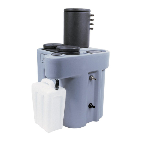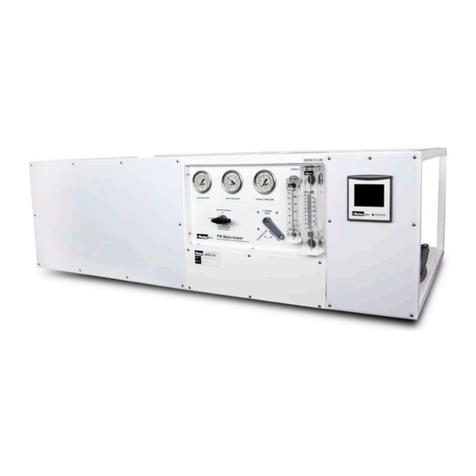
SMOGHOG Media Mist Collector SHM-05C & SHM-08C Models
ii
Table of Contents
Safety Precautions..............................................................................iii
1. Important Notice ............................................................................ 5
2. Introduction ................................................................................... 5
2.1. SMOGHOG Nomenclature ............................................................................. 5
2.2 Equipment Description ................................................................................... 6
2.3 Principal Of Operation .................................................................................... 8
3. Installation .................................................................................... 9
3.1 Inspection and Off Loading ............................................................................. 9
3.2 Installation Preparation and Planning ............................................................... 9
3.3 Discharge Component Installation.................................................................... 9
3.4 Mechanical Installation...................................................................................11
3.5 Electrical Connection .....................................................................................14
3.5.1 Electrical Supply Power ...............................................................................15
3.5.2 Electrical Basic Controls..............................................................................15
3.5.3 Advanced Option Unit..................................................................................17
3.5.4 Electrical Remote Panel Controls .................................................................17
3.5.5 Machine Interlock Dry Contact .....................................................................17
3.6 Filter Installation ............................................................................................17
3.6.1 Installation Procedure For After-Filter ...........................................................18
3.7 Drains ...........................................................................................................19
4. Unit Operation ..............................................................................19
4.1 Start-Up .......................................................................................................19
4.2 System Operation .........................................................................................20
4.2.1 Advanced Unit Operation ............................................................................20
4.2.1.1 Airflow Adjustment Using Manual Speed Control ........................................20
4.2.1.2 Airflow Adjustment Using Auto-Flow Control...............................................20
4.3 Touchscreen Operation..................................................................................20
4.3.1 Start-Up and Home Screen..........................................................................20
4.3.2 Standard Format.........................................................................................21
4.3.3 Basic Screens ............................................................................................22
4.3.4 Auto-Flow Screen .......................................................................................23
4.3.5 After-Filter..................................................................................................23
4.3.6 Customer Settings ......................................................................................23
5. Service ........................................................................................26
5.1 General Maintenance Guidelines.....................................................................26
5.2 Filter Service .................................................................................................27
5.2.1 Installation Procedure For Peach®Saturated Depth Filter Elements ................27
5.3 Contaminant Removal ....................................................................................27
6. Troubleshooting Guide ....................................................................28
7. Replacement Parts .........................................................................29
8. Appendix- Wiring Diagrams...............................................................31
