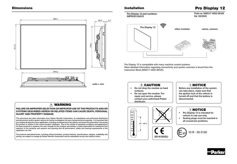
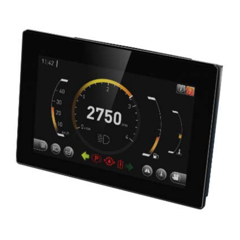
Parker PRO DISPLAY 12 User manual

Parker Pro Display 12 Instruction Book 2/54
Header Link to Contents
Parker Hannifin Manufacturing Finland Oy
Mobile Hydraulic Systems Division Europe (MSDE)
Electronic Controls Business Unit (ECBU)
Lepistönkatu 10
FI-30100 Forssa, Finland
Office +358 (0)20 753 2500
http://www.parker.com/ecd
Copyright 2019 © Parker Hannifin Corporation. All rights reserved. No part of this
work may be reproduced, published or distributed in any form or by any means
(electronically, mechanically, photocopying, recording or otherwise), or stored in a
database retrieval system, without the prior written permission of Parker Hannifin in each
instance.
WARNING!
FAILURE OR IMPROPER SELECTION OR IMPROPER USE OF THE PRODUCTS AND/OR SYSTEMS
DESCRIBED HEREIN OR RELATED ITEMS CAN CAUSE DEATH, PERSONAL INJURY AND
PROPERTY DAMAGE.
This document and other information from Parker Hannifin Corporation, its subsidiaries and authorised
distributors provide product and/or system options for further investigation by users with technical
expertise. It is important that you analyse all aspects of your application and review the information
concerning the product or system in the current product catalogue. Due to the variety of operating
conditions and applications for these products or systems, the user, through their own analysis and
testing, is solely responsible for making the final selection of the products and systems and assuring that
all performance, safety and warning requirements of the application are met.
The products described herein, including without limitation, product features, specifications, designs,
availability and pricing, are subject to change by Parker Hannifin Corporation and its subsidiaries at any
time without notice.

Parker Pro Display 12 Instruction Book 3/54
Header Link to Contents
Contents ........................................................................................................................3
Publication History........................................................................................................5
1. Introduction ...............................................................................................................6
1.1. Safety symbols....................................................................................................................6
1.2. Overview of relevant documentation...................................................................................6
2. Precautions................................................................................................................7
2.1. General safety regulations ..................................................................................................7
2.2. Safety ..................................................................................................................................7
2.3. Welding after installation .....................................................................................................7
2.4. Construction regulations .....................................................................................................7
2.5. Safety during installation .....................................................................................................8
2.6. Safety during start-up..........................................................................................................8
2.7. Safety during maintenance and fault diagnosis ..................................................................8
3. Diagram Conventions ...............................................................................................9
4. Product Description ................................................................................................11
4.1. General .............................................................................................................................11
4.2. System overview ...............................................................................................................14
4.3. Infotainment ......................................................................................................................16
4.3.1. Audio line I/O .......................................................................................................16
4.3.2. Audio line output ..................................................................................................16
4.3.3. Microphone input .................................................................................................17
4.3.4. FM radio tuner .....................................................................................................18
4.3.5. Wireless communication......................................................................................18
4.3.5.1. WLAN 802.11........................................................................18
4.3.5.2. Bluetooth...............................................................................18
4.4. Video inputs ......................................................................................................................18
4.5. Inputs/Outputs...................................................................................................................20
4.5.1. Ignition input ........................................................................................................20
4.5.2. Wake-up input......................................................................................................21
4.5.3. Digital output........................................................................................................21
4.6. Communication .................................................................................................................22
4.6.1. CAN .....................................................................................................................22
4.6.2. USB .....................................................................................................................22
4.6.3. RS232..................................................................................................................23
4.6.4. Ethernet ...............................................................................................................23
4.7. HMI (Human-Machine Interface).......................................................................................23
4.7.1. Touchscreen ........................................................................................................23
4.7.2. Display .................................................................................................................24
4.8. Internal features & diagnostics..........................................................................................25
4.8.1. Acceleration sensor .............................................................................................25
4.8.2. Supply supervision & voltage measurement .......................................................25
Contents

Parker Pro Display 12 Instruction Book 4/54
Header Link to Contents
4.8.3. Real time clock ....................................................................................................25
4.8.4. EEPROM .............................................................................................................25
4.8.5. Diagnostic LEDs ..................................................................................................26
4.8.6. Temperature sensor ............................................................................................26
4.9. Mass storage.....................................................................................................................26
5. Software...................................................................................................................28
5.1. General .............................................................................................................................28
5.2. Parker UX Toolkit ..............................................................................................................28
5.2.1. Parker UX Platform (UXP)...................................................................................28
5.2.2. Parker Application Designer ................................................................................28
5.3. UXP Configuration ............................................................................................................28
5.4. Installing and removing applications .................................................................................29
5.5. Pro Display operation modes............................................................................................30
5.5.1. Sleep mode..........................................................................................................31
5.6. Diagnostics........................................................................................................................31
6. Mechanics................................................................................................................32
6.1. Mechanical construction ...................................................................................................32
6.2. Dimensional drawing.........................................................................................................32
7. Mounting..................................................................................................................33
7.1. Mounting the module.........................................................................................................33
7.1.1. Assembly surface conciderations ........................................................................33
7.2. Dashboard or panel assembly ..........................................................................................33
7.2.1. Panel assembly ...................................................................................................33
7.3. Ball / swivel mount ............................................................................................................34
8. Installation ...............................................................................................................37
8.1. Electrical connections .......................................................................................................37
8.1.1. Main connectors C1 and C2 ................................................................................38
8.1.2. USB connections C3 and C4...............................................................................39
8.1.3. Video connection C5 ...........................................................................................40
8.1.4. Ethernet connection C6 .......................................................................................41
8.1.5. Micro SD card interface .......................................................................................42
8.1.6. Radio antenna connection...................................................................................44
8.2. Power supply considerations ............................................................................................45
8.2.1. Supply voltage .....................................................................................................45
8.2.2. Emergency stop...................................................................................................45
8.2.3. Connecting of supply voltage ..............................................................................45
8.2.4. RTC back-up supply ............................................................................................45
8.2.5. Polarity reversal ...................................................................................................46
9. Start-up ....................................................................................................................46
9.1. Procedures with software..................................................................................................46
10. Appendix A – Technical summary .......................................................................47
11. Appendix B – Environmental summary ...............................................................49
12. Appendix C - Ordering codes ...............................................................................54

Parker Pro Display 12 Instruction Book 6/54
Header Link to Contents
Do not perform the procedures in this manual unless you have experience in the
handling of electronic equipment.
Contact the manufacturer if there is anything you are unsure of, or if you have any
questions regarding the product and its handling or maintenance.
The term "manufacturer" refers to Parker Hannifin Corporation.
1.1. Safety symbols
The following symbols are used in this document to indicate potentially hazardous
situations:
Danger! Risk of death or injury.
Warning! Risk of damage to equipment or degradation of signal.
When you see these symbols, follow the instructions carefully and proceed with caution.
Note (character style): Note style for regular manual text.
1.2. Overview of relevant documentation
The following publications are relevant for users of this product. The main
documentation contains information that is not found elsewhere.
The additional documentation contains product information in a compact format. For
details on the information found in those documents, please consult this manual.
Table 2: Pro Display and UX Toolkit documentation
Document
Description
Instruction Book, Parker Pro Display 12
(This document)
Parker Pro Display Catalogue
MSG17-4015-UK
Parker UX Toolkit Catalogue
HY33-4812-UK
Installation Sheet, Parker Pro Display 12
MSG17-4022-IS/UK
System Certification Guide
HY33-4812-SCG/UK
E-Type Approval, Pro Display 12
E17 10-R-05 0150
1. Introduction

Parker Pro Display 12 Instruction Book 7/54
Header Link to Contents
2.1. General safety regulations
Work on the hydraulics control electronics may only be carried out by trained personnel
who are well-acquainted with the control system, the machine itself and its safety
regulations.
Follow the manufacturer's regulations when mounting, modifying, repairing and
maintaining equipment. The manufacturer assumes no responsibility for any accidents
caused by incorrectly mounted or incorrectly maintained equipment. The manufacturer
assumes no responsibility for the system being incorrectly applied, or for the system
being programmed in a manner that jeopardizes safety.
2.2. Safety
Do not use the product if electronic modules, cabling or connectors are damaged or if
the control system shows error functions. Electronic control systems in an inappropriate
installation and in combination with strong electromagnetic interference fields can, in
extreme cases, cause an unintentional change in the speed of the output function.
2.3. Welding after installation
Complete as much as possible of the welding work on the chassis before the installation
of the system. If welding has to be done afterwards, proceed as follows:
•Do not place the welding unit cables near the electrical wires of the control
system.
•Disconnect the electrical connections between the system and external
equipment.
•Disconnect the negative cable from the battery.
•Disconnect the positive cable from the battery.
•Connect the welder's ground wire as close as possible to the point of welding.
2.4. Construction regulations
The vehicle must be equipped with an emergency stop which disconnects the supply
voltage to the control system's electrical units. The emergency stop must be easily
accessible to the operator. If possible, the machine must be built so that the supply
voltage to the control system's electrical units is disconnected when the operator leaves
the operator’s station.
2. Precautions

Parker Pro Display 12 Instruction Book 8/54
Header Link to Contents
2.5. Safety during installation
Incorrectly positioned or incorrectly mounted cabling can be influenced by radio signals,
which can interfere with the functions of the system.
2.6. Safety during start-up
Danger! Risk of death or injury.
Do not start the machine's engine before the control system is mounted and its
electrical functions have been verified. Do not start the machine if anyone is near the
machine.
Ensure that no one is in front of, behind or nearby the machine when first starting up
the machine. Follow the instructions for function control in the Start-up section.
2.7. Safety during maintenance and fault
diagnosis
Before performing any work on the hydraulics control electronics, ensure that:
•The machine cannot start moving.
•Functions are positioned safely.
•The machine is turned off.
•The hydraulic system is relieved from any pressure.
•Supply voltage to the control electronics is disconnected.

Parker Pro Display 12 Instruction Book 9/54
Header Link to Contents
There are many connection diagrams to be found throughout this manual. The following
table provides meanings for the different symbols used in those diagrams:
Symbol Meaning
General input
General output
Frequency input
Analogue input
Frequency sensor
Resistive sensor
General sensor
Application switch
Emergency stop
Relay
3. Diagram Conventions

Parker Pro Display 12 Instruction Book 11/54
Header Link to Contents
4.1. General
Pro Display 12 is a member of Parker’s Pro Display product family. Pro Display is a
family of displays capable of running Parker UX Platform (UXP) applications created with
Parker Application Designer software development environment.
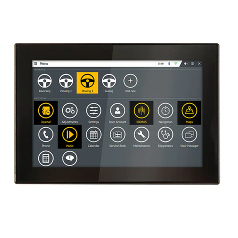
Figure 1: Pro Display 12
Table 3: Pro Display 12 product part numbers
Item P/N
Description
88PROD12AS10 12-inch sunlight readable display with touchscreen, 4
analog video inputs, infotainment features and high
performance with iMX6 Quad core processor, 1GB RAM &
2GB Flash memory
4. Product Description

Parker Pro Display 12 Instruction Book 12/54
Header Link to Contents
The following table summarises the characteristics offered by this product:
Table 4: Pro Display 12 product characteristics
Characteristic
Value
CPU NXP iMX6, Cortex A9 Quad
RAM 1GB
FLASH 2GB (4GB eMMC used in SLC mode)
EEPROM
32KB in main carrier for production data saving
External memory interface SD host interface for Micro SD/SDHC Card (in the back
side of the module, sealed with cover plug)
Communication media 1 x Ethernet 10 or 100 Mbps speed
4 x CAN
2 x USB 2.0
1 x RS232
1 x Bluetooth (in Advanced version only)
1 x WLAN (in Advanced version only)
Video input 4 x Composite video inputs with NTSC/PAL/SECAM
autodetection
Audio Stereo Line IN & Line OUT
Audio input sources (5 pcs) selectable from following:
a) Bluetooth audio
b) Audio line input (selectable with FM radio)
c) FM radio (selectable with audio line input)
d) Microphone input
e) Digital audio from module
Audio outputs (2 pcs) selectable from following:
f) Audio line output (to external amplifier)
g) Digital audio to module (record). As default
recording is disabled.
h) configurable auxiliary line output (alternative
to item b)
FM-Radio & antenna connector Yes
Microphone inputs Yes
Digital inputs 1 x Keylock (ignition) input
1 x Wake-up input
Outputs 1 x High-side output: 1500mA max
Internal features 3-axis acceleration sensor
Voltage measurement
Real Time Clock (RTC)
Diagnostic LED’s (for app. dev. purposes only)
Temperature measurement
Operating voltage range 9…36VDC
(12/ 24V nominal)
Operating temperature range
-30 °C … +70 °C
Storage temperature range
-40 °C … +85 °C

Parker Pro Display 12 Instruction Book 13/54
Header Link to Contents
Characteristic
Value
IP rating
IP65
Display type
TFT, Transmissive with LED backlight
Display size 12,1-inch
LCD active area: 261,12 mm x 163,2 mm
Display features Resolution: 1280 x 800
Luminosity / brightness: 900 cd/m2 (Typical)
Contrast ratio: 1000:1 (Typical)
Touchscreen Projected capacitive touchscreen (PCAP)
Sensor active area: 245,12 x 147,2 mm
Multi-finger support
Cover glass features Thickness: 1,8 mm
Glass type: Strenghtened, clear
Printing: Edge printing, Black
Touchscreen – display
mechanical interface
Optical bonding between cover glass and LCD display
glass for improved optical performance.
Product size
309,1 x 211,2 x 51,6 mm (width, height, depth)
Case material Front cover: PC-ABS
Back cover: Die casted Aluminium
Weight 1,96 kg
This manual describes the hardware components of the Pro Display 12, but it does not
explain how to configure nor develop the actual application software. For more
information about software, please refer to the appropriate software manual or contact
your Parker Account Representative.

Parker Pro Display 12 Instruction Book 14/54
Header Link to Contents
VOLTAGE INPUTS
SELECTABLE
AUDIO
IO
(LINE IN/OUT)
INTERNAL
POWER
SUPPLIES
POWER
SUPPLY
SUPERVISION
IGNITION IN
WAKE-UP IN
ACCEL.
SENSOR
RTC
POWER
SUPPLY
INPUT
EEPROM
VIDEO
CODEC
AUDIO
CODEC
COMMUNICATION BUSES
CAN 1
ETHERNET
RS232
USB 0
USB 1
CAN 2
CAN 3
CAN 4
CPU
Environment
1GB
RAM
2GB
FL ASH
MASS STORAGE
SD HOST
AUDIO SOURCES
MIC BIAS
FM RADIO
MIC IN
AUDIO
LINE IN
WIRELESS INTERFACES
BLUETOOTH WIFI
BT
HANDSFREE
12,1" TFT
DISPLAY
TOUCHSCREEN
HS OUT
AUDIO
LINE OUT
CAMERA INPUTS
VIDEO IN 1
VIDEO IN 2
VIDEO IN 3
VIDEO IN 4
CoCPU
TEMP.
SENSOR
Figure 2: Pro Display 12 block diagram.
4.2. System overview
Parker Pro Display can be a central Human Machine Interface (HMI) unit in the system
or a stand-alone display. Pro Display is not limited to one particular control system
integration. Pro Display has four CAN buses, one Ethernet port, two USB ports, one
RS232 port, two video inputs and digital ignition and wake-up inputs. SAE J1939 and

Parker Pro Display 12 Instruction Book 15/54
Header Link to Contents
Generic CAN protocols are supported on the CAN buses, which allows for the possibility
to connect Pro Display to third party modules.
Pro Display also supports WLAN and Bluetooth wireless communications and therefore
it can be connected to mobile phones, tablets, laptop computers etc. for audio
streaming, video sharing and overall data communication between the devices.
HMI is implemented by a projective capacitive touchscreen and a high performance
TFT-LCD display panel. All I/O are protected against short circuit to GND and VBatt as
well as against reverse polarity. Pro Display is intended for systems using either nominal
12 or 24VDC voltage. The unit has a wide supply voltage range – from 9 to 36VDC.
CAN
CONTROLLER
CAN
CONTROLLER
CAN BUS 2
CAN
CONTROLLER
CAN
CONTROLLER
CAN BUS 3
ETHERNET
DEVICE
ETHERNET
IO EXPANSION
BT,
BT HF
WIFI
CAN
DEVICE
CAN
DEVICE
CAN BUS 1
SPEAKERS
MIC IN
LINE IO
VIDEO IN 1
VIDEO IN 2
CAMERA A
CAMERA B
CAN BUS 4
CAMERA C
CAMERA D
VIDEO IN 3
VIDEO IN 4
AUDIO
DEVICE
PRO DISPLAY 12 LINE OUT
LINE OUT
Figure 3: Pro Display 12 system overview. This figure shows just one possible application.

Parker Pro Display 12 Instruction Book 16/54
Header Link to Contents
4.3. Infotainment
4.3.1. Audio line I/O
This product has one unbalanced stereo line I/O that can be configured to “Audio Line
IN” or “Audio Line OUT” -mode.
Audio input volume is adjustable through the use of software. Microphone input and
warning tones can be mixed to any selected audio source.
There are five different audio sources to be selected to use with Audio Line IN -mode:
•Bluetooth audio
•Audio line input (selectable with FM radio)
•FM radio (selectable with audio line input)
•Microphone input (internally connected to audio codec and Bluetooth module)
•Module internal (digital audio from module)
When Audio Line I/O is configured to Audio Line OUT mode, its working like normal Line
Output. In Line IN mode this I/O is normal Line Input.
Table 5: Audio Line IO specifications, Line IN- mode.
(See Line OUT -mode specification from table 6)
Feature
Spec
DC input impedance 11,5 kOhm
Maximum input voltage 1 Vrms
Bandwidth 10 Hz – 26 kHz/-3dB
PRO DISPLAY
AUDIO
LINE-
IN
AUDIO_LINE_IN_OUT_R
AUDIO_LINE_IN_OUT_L
EXTERNAL AUDIO
SOURCE
C2:6
C2:8
C2:9
AUDIO_GND
Figure 4: Audio Line I/O working as Line input -mode.
4.3.2. Audio line output
There is one optional unbalanced stereo line output which can be connected to an
external amplifier. Output amplitude can be adjusted through the use of software.
There are two audio outputs to be selected:
•Audio line output (to external amplifier)
•Digital audio to module (record). Recording is disabled by default in Pro Display.

Parker Pro Display 12 Instruction Book 17/54
Header Link to Contents
Table 6: Audio Line OUT and Line OUT- mode specifications
Feature Spec
Output impedance 150 Ohm
Maximum output voltage 0,5 Vrms
Bandwidth 15 Hz – 20 kHz /-3 dB
PRO DISPLAY
AUDIO
LINE OUT
AUDIO_GND
SPEAKER R
SPEAKER L
AUDIO_LINE_OUT_R
AUDIO_LINE_OUT_L
C2:5
C2:4
C2:6
EXTERNAL AUDIO
AMPLIFIER
Figure 5: Pro Display line output. Picture shows connection principle for two channels. It
is possible to also utilise single channel if this would be adequate for the end application.
4.3.3. Microphone input
Microphone input is provided. Microphone input can be used for both general and
hands-free purposes. Microphone input volume is adjustable with software. This input
has a bias voltage output for electret microphones.
Table 7: Microphone input- specifications
Feature
Spec
DC input impedance 2 kOhm
Maximum input voltage 215 mVrms
Bandwidth 35 Hz – 16 kHz/-3 dB
Bias voltage: 2,5V (typical)
MICROPHONE
PRO DISPLAY
MIC
BIAS
MIC IN
MIC_P
MIC_N
MIC_BIAS
C2:11
C2:10
C2:12
Figure 6: Pro Display microphone input

Parker Pro Display 12 Instruction Book 18/54
Header Link to Contents
4.3.4. FM radio tuner
RDS FM radio tuner is one of the audio sources in Pro Display. A connector for attaching
an external antenna into Pro Display is also provided. FM radio feature is selectable so
that either FM radio or Audio line inputs serve as the audio source. Pro Display radio
includes complete RDS-FM tuner functionality with seek tuning within 76 to 108 MHz
frequency range, automatic frequency and gain control features, as well as volume
control and adaptive noise suppression.
NOTICE: Check the supported software features for RDS-FM Radio before
application software creation.
4.3.5. Wireless communication
4.3.5.1. WLAN 802.11
Pro Display can be connected to wireless local area network (WLAN) access points.
This makes it possible to connect to external networks via mobile phone and use, for
example, online map provider services. Standards IEEE 802.11b, 802.11g and
extension 802.11n are supported.
Parker has an example application called “Settings”. This example application can be
used for scanning available access points and to make connections with desired access
points.
4.3.5.2. Bluetooth
Pro Display includes wireless Bluetooth function to connect other Bluetooth devices.
Bluetooth supports for example Serial Port Profile (SPP), Hands Free Protocol (HFP)
and A2DP for audio streaming,
NOTICE: If echo cancelling functionality for hands-free is needed, please contact
your Parker Account Representative.
It is also possible to connect a Bluetooth device to Pro Display and transfer, for example,
diagnostic data via serial port protocol.
NOTICE: Connected device shall have suitable application for allowing wireless data
transfer to/from Pro Display.
4.4. Video inputs
Pro Display 12 has 4 pcs of analogue composite video inputs, CVBS IN 1, CVBS IN 2,
CVBS_IN3 and CVBS_IN4. All video inputs have NTSC/PAL/SECAM autodetection.
Power supply for external cameras is intended to be arranged from elsewhere in system
where Pro Display 12 is installed - not from Pro Display 12 as there is no dedicated
power supply for the purpose. See figure 7 for camera connection principle.
Table 8: Video input specifications
Feature
Spec
Signal level 1,9 Vp-p (typical)
Input impedance 75 Ohm

Parker Pro Display 12 Instruction Book 19/54
Header Link to Contents
CVBS_IN 1
CVBS_IN 2
VIDEO SIGNAL
VIDEO SIGNAL
12V
Video GND
Video GND
Video GND
GND
CAMERA1
CAMERA2
CAMERA3
CAMERA4
VIDEO SIGNAL
Video GND
VIDEO SIGNAL
Video GND
CVBS_IN 3
CVBS_IN 4
12V
GND
12V
GND
12V
GND
12V
GND
-+ 12V
Ext. Camera
supply
+
-
VIDEO INPUTS
VIDEO
IN 1
VIDEO
IN 2
PRO DISPLAY 12
C5:4
C5:1
C5:5
VIDEO
IN 3
VIDEO
IN 4
C5:2
C5:3
C5:Shield
Figure 7: Video Camera connection principle for 4 cameras in Pro Display 12. Ground
connections shall be considered with external supply to avoid ground loops.

Parker Pro Display 12 Instruction Book 20/54
Header Link to Contents
4.5. Inputs/Outputs
4.5.1. Ignition input
One ignition (keylock) input is provided and it has following specifications:
Table 9: Ignition input- specifications
Feature
Spec
Input voltage range ON > 6V
Input voltage range OFF < 3V
Input voltage tolerance
± 10 %
Input voltage range to
enter Maintenance mode
> 36V
Cut-off frequency 102 Hz
Input impedance
38 kΩ
When VBatt is disconnected the module cannot be powered through ignition. This multi-
level, digital ignition signal has following functional states:
Table 10: Ignition- signal functionality
State Functionality
OFF Inactive; the main power is switched off if
the internal ‘Keep alive’ control signal is
off.
ON Active; switches the main power on, or
wakes the module up from sleep
MAINTENANCE Used for software download and service
purposes
PRODISPLAY
IGNITION IN
KEYLOCK
IGNITION
C1:6
C1:1
Figure 8: Ignition input connection principle
Maintenance mode is intended for the following:
•Installing new software packages
•Updating existing software packages
•Removing existing software packages
Other manuals for PRO DISPLAY 12
1
This manual suits for next models
1
Table of contents
Other Parker Monitor manuals

Parker
Parker IQAN MDM User manual

Parker
Parker PHD28 User manual

Parker
Parker IQAN-MD3 User manual

Parker
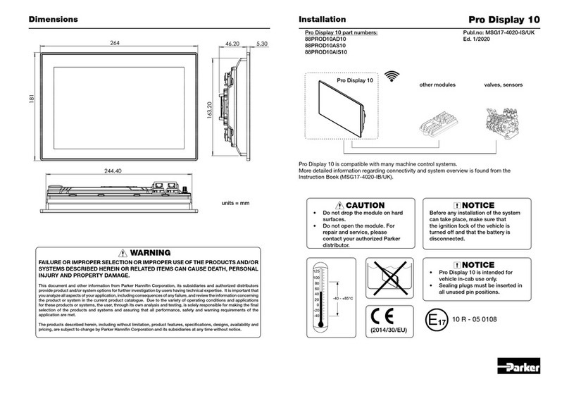
Parker Pro Display 10 User manual

Parker
Parker PRO DISPLAY 12 User manual

Parker
Parker Pro Display 10 User manual

Parker
Parker 71-313 Series User manual

Parker
Parker IQAN-MD4 User manual

Parker
Parker Pro Display 10 User manual

Parker
Parker Airtek DB1000 Owner's manual