© 2015 Parker Hannin Corporation Parker Hannin Corporation
Electromechanical Automation Div.
135 Quadral Drive
Wadsworth, OH 44281 USA
Tel: 800.333.4932 or 330-335-6740
Fax: 330.334.2350
5500 Business Park Drive
Rohnert Park, CA 94928
Tel: 800.358.9070
Fax: 707.584.8029
Email: ipsquotes@parker.com or emn_support@parker.com
Part Number: 70-104
Print Date 6.15.15
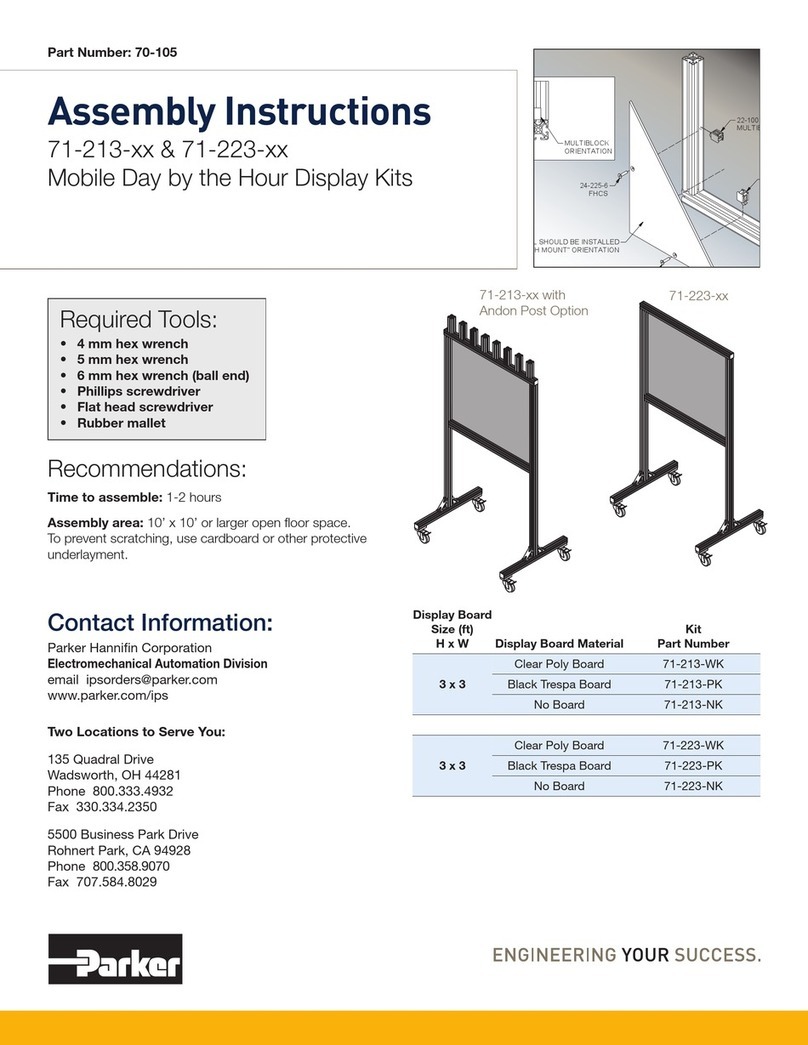
Assembly Instructions for 71-113-xx & 71-123-xx Kits:
24-118-8
20-058
20-111
24-125-8 BHCS
24-525-10F
SET SCREW
THRU HOLE FOR
FLOOR MOUNTING
Step 2
At eight locations of display frame
marked 2, use 22-100 Multiblock
fasteners to attach the display panel
to the frame.
A. Insert multiblocks into T-slot and rotate
90° clockwise
B. Place panel into position and verify
alignment of multiblocks with panel
holes.
C. Insert 24-2225-6 screws though panel
holes and into multiblocks to secure
panel.
22-100
MULTIBLOCK
22-100
MULTIBLOCK
24-225-6
FHCS
24-225-6
FHCS
PANEL SHOULD BE INSTALLED
IN "FLUSH MOUNT" ORIENTATION
MULTIBLOCK
ORIENTATION
Step 3
Attach the display post (Beam #3) to bottom
of the display frame (Beam #1B) using 20-111
Joining Plates
A. Roll 20-058 T-nuts into slot.
B. Place joining plate in position and secure with 24-118-8
BHCS screws.
C. Repeat on other side of
post and frame
Step 4
Secure Finished Assembly to
Floor with 27-055 Flange Foot
A. Insert 24-525-10F set screw levelers into ange foot.
B. Use appropriate fasteners (not provided) to attach the
ange foot to oor
C. Insert 24-125-8 Retaining Bolts to secure the post to
ange foot.
D. Adjust set screw levelers to plum the assembly.
