6
SUB MENUS
The system consist of five sub menus which allow for settings of the screen, adjusting
machine settings, measuring, and setting operators. The five sub Screens are:
MODE- IQAN Allows for Four different operator settings which are selected in the MODE
screen. This means a Day shift operator can tune a machine with different maximum
speeds and ramps on the outputs for the system. A 2nd Shift operator can be MODE 2
which may be set a little slower our have smoother ramping than the day shift operator.
Mode 4 is often a factory default setting and no changes can be made to this Mode.
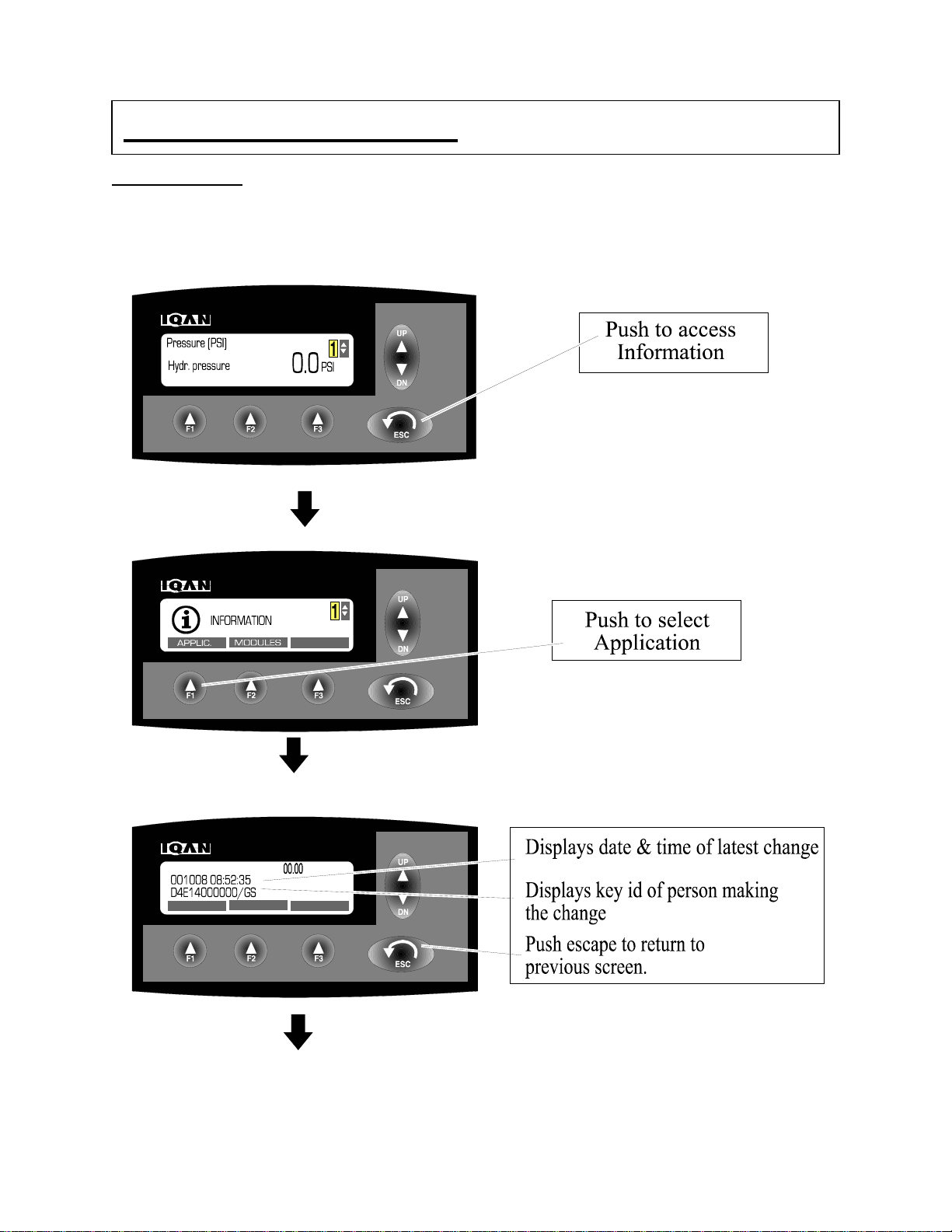
INFORMATION- Informs on the Application including serial Number Identification and
comments from the manufacturer. Also, all information on module communication and
status is displayed in the INFORMATION screen. This allows review of each module of
the system to determine if components are on line and enabled.
SETTINGS-The changes on this are for informational configuration for the operator of the
machine. Changes include Light and Contrast adjustment. Language change from the
primary language to the alternate language, such as English to French. Set Volume on
Alarm Buzzer. Set Date and Time of Real Time clock.
MEASURE- The MEASURE menu allows the operator to monitor all inputs or outputs of
the IQAN system. This feature when used is the one of the most powerful aspects for the
machine control system. A malfunction or performance variance can easily be viewed
from the screen. This has several modes including % signal monitoring, millivolt or
milliamp monitoring, or as a rudimentary oscilloscope.
PROPERTIES- The PROPERTIES menu allows the operator to set the adjustable
parameters for inputs or outputs as determined by the manufacturer of the machine. This
allows operator 1 to set the minimum current, maximum current to a valve which can
control minimum flow and maximum flow of a function. The start Ramps and stop ramps
for extending or retracting a cylinder. Ability to set a two slope control on a function for a
creep then high speed control.
With the five submenus the machine can be tuned to meet several different operators
needs. Also, allow for very quick troubleshooting of the system .
THIS DOES NOT REQUIRE A PHD DEGREE IN COMPUTER SCIENCE. By following
the commands of this book a operator can become very proficient in the control and
trouble shooting of the machine.