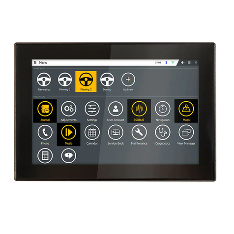
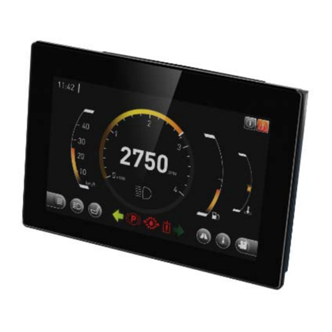
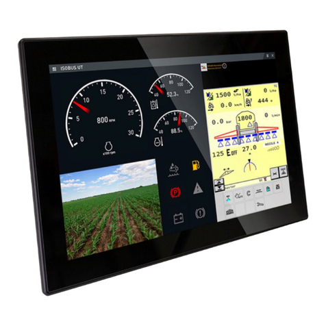
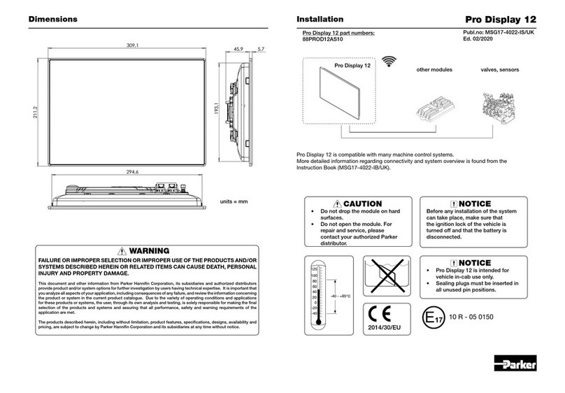
Parker PHD Series User manual

Parker Hannifin Display
PHD
User Guide
UG-PHD-1040001-201907-018

Parker Hannifin Canada
Electronic Controls Division
1305 Clarence Avenue
Winnipeg, MB R3T 1T4 Canada
office +1 204 452 6776
Fax +1 204 478 1749
http://www.parker.com/ecd
Copyright 2019 © Parker Hannifin Corporation. All rights reserved. No part of this work may be
reproduced, published, or distributed in any form or by any means (electronically, mechanically,
photocopying, recording, or otherwise), or stored in a database retrieval system, without the prior
written permission of Parker Hannifin Corporation in each instance.
Warning!
FAILURE OR IMPROPER SELECTION OR IMPROPER USE OF THE PRODUCTS AND/OR SYSTEMS
DESCRIBED HEREIN OR RELATED ITEMS CAN CAUSE DEATH, PERSONAL INJURY AND PROPERTY
DAMAGE.
•This document and other information from Parker Hannifin Corporation, its subsidiaries and authorized
distributors provide product and/or system options for further investigation by users having technical expertise.
•The user, through its own analysis and testing, is solely responsible for making the final selection of the
system and components and assuring that all performance, endurance, maintenance, safety and warning
requirements of the application are met. The user must analyze all aspects of the application, follow applicable
industry standards, and follow the information concerning the product in the current product catalog and in any
other materials provided from Parker or its subsidiaries or authorized distributors.
•To the extent that Parker or its subsidiaries or authorized distributors provide component or system options
based upon data or specifications provided by the user, the user is responsible for determining that such data
and specifications are suitable and sufficient for all applications and reasonably foreseeable uses of the
components or systems.
•The Buyer and/or end-user will be solely responsible for final disposal of all products.

iii
Publication History ...............................................................................................................v
Safety ....................................................................................................................................vi
Safety symbols.................................................................................................................................vi
General safety regulations...............................................................................................................vi
Welding after installation.................................................................................................................vii
Construction regulations .................................................................................................................vii
Safety during installation.................................................................................................................vii
Safety during start-up.....................................................................................................................viii
Safety during maintenance and fault diagnosis.............................................................................viii
1. About the PHD (Parker Hannifin Display).......................................................................1
1.1. Diagram conventions ................................................................................................................5
2. Connectors........................................................................................................................7
2.1. Pinouts......................................................................................................................................8
3. Inputs ...............................................................................................................................13
3.1. PHD28 inputs..........................................................................................................................13
3.2. PHD50 inputs..........................................................................................................................14
3.3. PHD70 inputs..........................................................................................................................15
3.3.1. PHD28/PHD50 analog input capabilities...................................................................16
3.3.2. PHD28/PHD50/PHD70 digital input capabilities........................................................18
3.3.3. PHD50/PHD70 frequency input capabilities..............................................................20
3.4. Using inputs as low power outputs.........................................................................................22
3.4.1. Low power, high-side output capabilities...................................................................22
4. Outputs ............................................................................................................................24
4.1. PHD28/PHD50/PHD70 Low-side outputs...............................................................................24
4.1.1. Low-side output capabilities ......................................................................................24
4.2. Sensor and regulated supply outputs .....................................................................................26
4.2.1. Sensor and regulated supply capabilities..................................................................27
5. Power ...............................................................................................................................28
6. Communication...............................................................................................................29
6.1. Controller Area Network..........................................................................................................29
6.1.1. CAN capabilities ........................................................................................................29
6.1.2. PHD CAN installation connections............................................................................30
Contents

iv PHD
Contents
6.2. USB .........................................................................................................................................32
7. HMI (Human Machine Interface) ....................................................................................33
7.1. Ambient light sensor................................................................................................................33
7.2. Touchscreen............................................................................................................................33
7.3. Keypad.....................................................................................................................................33
7.4. Buzzer......................................................................................................................................33
7.5. Video........................................................................................................................................34
7.5.1. Video Input Capabilities.............................................................................................34
8. Serial Ethernet Recovery Flexcan (SERF) Development Board.................................35
8.1. SERF overview........................................................................................................................35
8.2. Available Inputs and Outputs...................................................................................................36
8.2.1. Switches and Connectors ..........................................................................................37
8.2.2. Jumpers......................................................................................................................38
8.2.3. DB9 Pinout Reference...............................................................................................41
9. Mounting the PHD...........................................................................................................42
9.1. Dimensions..............................................................................................................................43
9.1.1. PHD28........................................................................................................................43
9.1.2. PHD50........................................................................................................................44
9.1.3. PHD70........................................................................................................................45
10. Understanding PHD software ......................................................................................46
11. Environmental protection ............................................................................................47
EMI 47
Mechanical environment.................................................................................................................47
ESD 47
Climate environment.......................................................................................................................47
Chemical environment....................................................................................................................48
12. Index...............................................................................................................................49

v
The following table provides an overview of the changes made to this document
over the course of its publication history.
Release Date
Description of Change
Rev. 001
First release of this document, 2/10/2016
Rev. 002
Updated per Bus. Dev. feedback, 3/3/2016
Rev. 003
Incremental updates from case 30666 reviews 4/6/2016 and
6/27/2016
Rev. 004
Edits based on case 30666 7/11/2016 review and 1042F06
specification
Rev. 005
Edits based on case 30666 9/12/2016 review
Rev. 006
Inputs, outputs and 5V / 12V power supply outputs, pin
naming changed, 1/11/2017
Rev. 007
Remove references to Advanced versions per Sales and
Marketing request. Will launch at a later date.
Rev. 008
Label pins in C2 as reserved for PHD50/PHD70
Rev. 009
Add SERF Development board section
Rev. 010
High-side/low power output and low-side output specification
update.
Rev. 011
Changed PHD70 brightness specification.
Rev. 012
Minor edit to Power section
Rev. 013
Added RS232 debugging pin names to PHD50/70 connector
C2 pin-out
Rev. 014
Minor edits to SERF board section.
Rev. 015
Minor edit to Power section.
Rev. 016
Minor edit to PHD70 feature table and Environmental
protection section, 1/29/2018
Rev. 017
Removed reference to Digital inputs from PHD28/50, added
USB file loading and Recovery switch information.
Rev. 018
Edits per Product Manager markups 3/2019 and 6/2019
Publication History

vi
Do not perform the procedures in this manual unless you are experienced in the
handling of electronic equipment.
Contact the manufacturer if there is anything you are not sure about or if you have
any questions regarding the product and its handling or maintenance.
The term "manufacturer" refers to Parker Hannifin Corporation.
Safety symbols
The following symbols are used in this document to indicate potentially
hazardous situations:
Danger! Risk of death or injury.
Warning! Risk of damage to equipment or degradation of signal
When you see these symbols, follow the instructions carefully and proceed with
caution.
General safety regulations
Work on the hydraulics control electronics may only be carried out by trained
personnel who are well-acquainted with the control system, the machine, and its
safety regulations.
Follow the manufacturer's regulations when mounting, modifying,
repairing, and maintaining equipment. The manufacturer assumes no
responsibility for any accidents caused by incorrectly mounted or
incorrectly maintained equipment. The manufacturer assumes no
responsibility for the system being incorrectly applied, or the system
being programmed in a manner that jeopardizes safety.
Safety

vii
Safety
Do not use the product if electronic modules, cabling, or connectors are
damaged or if the control system shows error functions.
Electronic control systems in an inappropriate installation and in
combination with strong electromagnetic interference fields can, in
extreme cases, cause an unintentional change of speed of the output
function.
Welding after installation
Complete as much as possible of the welding work on the chassis before the
installation of the system. If welding has to be done afterwards, proceed as
follows:
Do not place the welding unit cables near the electrical wires of the
control system.
1. Disconnect the electrical connections between the system and external
equipment.
2. Disconnect the negative cable from the battery.
3. Disconnect the positive cable from the battery.
4. Connect the welder's ground wire as close as possible to the place of the
welding.
Construction regulations
The vehicle must be equipped with an emergency stop which disconnects the
supply voltage to the control system's electrical units. The emergency stop must
be easily accessible to the operator. If possible, the machine must be built so that
the supply voltage to the control system's electrical units is disconnected when the
operator leaves the operator’s station.
Safety during installation
Incorrectly positioned or mounted cabling can be influenced by radio
signals, which can interfere with the functions of the system.

viii PHD
Safety
Safety during start-up
Danger! Risk of death or injury. Do not start the machine's engine
before the control system is mounted and its electrical functions have
been verified.
Do not start the machine if anyone is near the machine.
Safety during maintenance and fault diagnosis
Before performing any work on the hydraulics control electronics, ensure that
▪The machine cannot start moving.
▪Functions are positioned safely.
▪The machine is turned off.
▪The hydraulic system is relieved from any pressure.
▪Supply voltage to the control electronics is disconnected.

1
The PHD family of displays are general purpose displays suitable for a wide
range of industry applications. There are 3 sizes: 2.8", 5.0" and 7.0". All models
are color LCD displays with capacitive touchscreens for interfacing.
Figure 1: PHD family of displays
1. About the PHD (Parker Hannifin Display)

2 PHD
About the PHD (Parker Hannifin Display)
The different models of the PHD and their features are listed in the following
tables:
PHD28
Characteristic
Description
Display
Viewing angle
Brightness
Contrast ratio
Readable with polarized glasses
2.8" 320 x 240 TN LCD, PCAP touchscreen
Aspect ratio 4:3
Theta X +60° / -60°, Theta Y +60° / -50°
500 cd/m²
500:1
yes (landscape and portrait orientation)
Processor
Vybrid VF5xxR (Cortex-A5 core)
Flash 16 MB
RAM 128 MB DDR
Communication
CAN x 1
USB Host/Device x 1 (default is Device)
Inputs
7 General Purpose Inputs;
7 - Analog or
7 - GPIO used for Keypad Interface
Ambient Light Sensor
Outputs
2 x low-side 500mA
1 x 5Vdc sensor supply 500mA
1 x 12Vdc sensor supply 500mA
up to 7 high-side, 4.3V @ 5mA
Wake-up sources
Power, CAN, Touch Screen, External Keypad (GPIO)
Heater for cold applications
High wattage resistors (built-in)
Connector
Molex MX150, 20 pin

3
About the PHD (Parker Hannifin Display)
PHD50
Characteristic
Description
Display
Viewing angle
Brightness
Contrast ratio
Readable with polarized glasses
5.0" 800 x 480 TN LCD, PCAP touchscreen
Aspect ratio 16:9
Theta X +80° / -80°, Theta Y +80° / -80°
380 cd/m²
500:1
yes (landscape and portrait orientation)
Processor
Vybrid VF5xxR (Cortex-A5 core)
Flash 32 MB
RAM 128 MB DDR
Communication
CAN x 1
USB Host/Device x 1 (default is Device)
Inputs
10 General Purpose Inputs;
2 - Frequency Inputs (for rotary encoder)
8 -Analog or
8-10 GPIO for Keypad Interface
Ambient Light Sensor
1 Video inputs (NTSC, PAL)
Outputs
2 x low-side 500mA
1 x 5Vdc sensor supply 500mA
1 x 12Vdc sensor supply 500mA
up to 10 high-side, 4.3V @ 5mA
Wake-up sources
Power, CAN, Touch Screen, External Keypad (GPIO),
Encoder
Heater for cold applications
High wattage resistors (built-in)
Connector
2 x Molex MX150, 20 pin

4 PHD
About the PHD (Parker Hannifin Display)
PHD70
Characteristic
Description
Display
Viewing angle
Brightness
Contrast ratio
Readable with polarized glasses
7.0" 800 x 480 IPS LCD, PCAP touchscreen
Aspect ratio 16:9
Theta X +80° / -80°, Theta Y +80° / -80°
430 cd/m²
600:1
yes (landscape and portrait orientation)
Processor
Freescale iMX6Solo/Dual/Quad
Flash 1 GB
RAM 512 MB DDR3
Communication
CAN x 2
USB Host/Device x 1 (default is Device)
Inputs
10 General Purpose Inputs;
2 - Frequency Inputs (for rotary encoder)
8 - Digital (active-high/low) or
8-10 GPIO for Keypad Interface
Ambient Light Sensor
2 simultaneous Video Inputs (NTSC, PAL)
Outputs
2 x low-side 500mA
1 x 5Vdc sensor supply 500mA
1 x 12Vdc sensor supply 500mA
up to 10 high-side, 4.3V @ 5mA
Wake-up sources
Power, CAN1, CAN2, Touch Screen, External Keypad
(GPIO), Encoder
Connector
2 x Molex MX150, 20 pin

5
About the PHD (Parker Hannifin Display)
1.1. Diagram conventions
The following symbols are used in the schematic diagrams in this document:
Symbol
Meaning
General input
General output
Frequency input
Analog input
Frequency sensor
Pulse sensor
Resistive sensor
General sensor
Application switch
Load
Pull-down resistor

6 PHD
About the PHD (Parker Hannifin Display)
Symbol
Meaning
Pull-up resistor
Battery
Fuse
Resistor
Ground
Chassis ground

7
Connectors
The connector on the rear panel of the PHD28 is;
▪MX150 –Vehicle Harness Connector key B
The connectors on the rear panel of the PHD50 are;
▪2 x MX150 –Vehicle Harness Connectors, key A & B
The connectors on the rear panel of the PHD70 are;
▪2 x MX150 –Vehicle Harness Connectors, key A & B
The Molex MX150 connectors are used to interface the PHD family to power,
inputs, outputs and USB.
Figure 2: MX150 20-pin connector
Mating Connector Part Numbers
PHD
Connector
Shell part no.
with locking clip
Shell part no.
without locking
clip
Terminals
J1 connector (gray),
20-pin, key option B
33472-2007
33472-2002
33001-2004
(18-20 AWG)
J2 connector (black),
20-pin, key option A
33472-2006
33472-2001
33001-2004
(18-20 AWG)
2. Connectors

8 PHD
Connectors
2.1. Pinouts
The pins in the Molex MX150 connectors connect to power, inputs, outputs, CAN
and USB communication channels.
The following tables show the pinouts for each connector:
Figure 3: Back of PHD28 showing connector
PHD28 J1 Connector Pinout
Pin
Function
1
GPIO7 (analog input/low power output)
2
GPIO1 (analog input/low power output)
3
GPIO6 (analog input/low power output)
4
OUTPUT2 (low-side output)
5
CAN1_TERM (CAN termination)
6
CAN1_SHLD (CAN shield)
7
CAN1_L (CAN low)
8
CAN1_H (CAN high)
9
GND (Negative battery)
10
+VBATT (Positive battery)
11
GPIO5 (analog input/low power output)
12
GPIO4 (analog input/low power output)
13
GPIO3 (analog input/low power output)
14
GPIO2 (analog input/low power output)
15
USB_D-
16
USB_D+
17
USB_GND
18
USB_VBUS / P5V0 (5V sensor supply)
19
P12V0 (12V regulated supply)
20
OUTPUT1 (low-side output)

9
Connectors
Figure 4: Back of PHD50 showing connectors
PHD50 J1 Connector Pinout
Pin
Function
1
GPIO7 (analog input)
2
GPIO1 (analog input)
3
GPIO6 (analog input/low power output)
4
OUTPUT2 (low-side output)
5
CAN1_TERM (CAN termination)
6
CAN1_SHLD (CAN shield)
7
CAN1_L (CAN low)
8
CAN1_H (CAN high)
9
GND (Negative battery)
10
+VBATT (Positive battery)
11
GPIO5 (analog input/low power output)
12
GPIO4 (analog input/low power output)
13
GPIO3 (analog input/low power output)
14
GPIO2 (analog input/low power output)
15
USB_D-
16
USB_D+
17
USB_GND
18
USB_VBUS (5V supply)
19
P12V0 (12V regulated supply)
20
OUTPUT1 (low-side output)

10 PHD
Connectors
PHD50 J2 Connector Pinout
Pin
Function
1
GPIO10 (digital or frequency input)
2
GPIO9 (digital or frequency input)
3
NC
4
NC
5
NC
6
VIDEO1_GND
7
VIDEO1
8
NC
9
Ground
10
P12V0 (12V regulated supply)
11
Ground
12
Ground
13
GPIO8 (analog input)
14
P5V0 (5V sensor supply)
15
RS232-RX (debugging use only)
16
RS232-TX (debugging use only)
17
NC
18
NC
19
NC
20
NC

11
Connectors
Figure 5: Back of PHD70 showing connectors
PHD70 J1 Connector Pinout
Pin
Function
1
GPIO7 (digital input/low power output)
2
GPIO1 (digital input/low power output)
3
GPIO6 (digital input/low power output)
4
OUTPUT2 (low-side output)
5
CAN1_TERM (CAN termination)
6
CAN1_SHLD (CAN shield)
7
CAN1_L (CAN low)
8
CAN1_H (CAN high)
9
GND (Negative battery)
10
+VBATT (Positive battery)
11
GPIO5 (digital input/low power output)
12
GPIO4 (digital input/low power output)
13
GPIO3 (digital input/low power output)
14
GPIO2 (digital input/low power output)
15
USB_D-
16
USB_D+
17
USB_GND
18
USB_VBUS (5V supply)
19
P12V0 (12V regulated supply)
20
OUTPUT1 (low-side output)

12 PHD
Connectors
PHD70 J2 Connector Pinout
Pin
Function
1
GPIO10 (digital or frequency input/low power output)
2
GPIO9 (digital or frequency input/low power output)
3
CAN2_SHLD
4
CAN2_L
5
CAN2_H
6
VIDEO1_GND
7
VIDEO1
8
VIDEO2
9
VIDEO2_GND
10
P12V0 (12V regulated supply)
11
Ground
12
Ground
13
GPIO8 (digital input)
14
P5V0 (5V sensor supply)
15
RS232-RX (debugging use only)
16
RS232-TX (debugging use only)
17
NC
18
NC
19
NC
20
NC
Other manuals for PHD Series
1
This manual suits for next models
3
Table of contents
Other Parker Monitor manuals

Parker
Parker Pro Display 10 User manual

Parker
Parker IQAN-MD3 User manual

Parker
Parker Pro Display 10 User manual

Parker
Parker Pro Display 10 User manual

Parker
Parker SciCon II Assembly instructions

Parker
Parker Airtek DB1000 Owner's manual

Parker
Parker PHD28 User manual

Parker
Parker 71-213 Series User manual

Parker
Parker PRO DISPLAY 12 User manual

Parker
Parker 71-113 Series User manual