manuals.online logo
Brands
  1. Home
  2. •
  3. Brands
  4. •
  5. Parker
  6. •
  7. Water Filtration System
  8. •
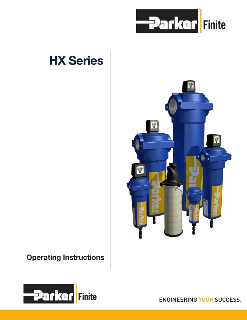
  9. Parker Finite H-Series Manual

Parker Finite H-Series Manual

19
Compressed Air
and Gas Filters
Parker Hannifin Corporation
Finite Filter Operation
Oxford, MI
Problem Probable Cause Solution
Too High Initial Air ow Excessive for housing size. Install larger lter.
Pressure Drop Filter media grade too ne. Install coarser element.
Too much oil/water from compressor. Pre-coalesce with grade 10 - oversize
housing.
Premature Clogging Lubricant improperly selected for compressor, Change oil, consult with lubricant
(Air Flow Drops Off) causing varnish or carbonizing of lubricant. supplier.
Excessive inlet particulate contamination. Prelter with Interceptor.
Excessive lubricants present on element caused Prelter with Grade 10 and oversize
by either high lubricant viscosity or very high coalescer to compensate.
inlet aerosol level.
Oil/water emulsion forming on element. Remove water by drip leg, aftercooler.
Install mechanical separator upstream.
Ice forming or oil viscosity too high due to Raise temperature.
Excessively low unit temperature.
Oil Present Down- Bowl not properly drained of waste liquids. Drain regularly, use auto drain.
stream of Filter
Element not sealing. Replace element.
Filter piped backwards. See "INSTALLATION"; Re-pipe.
Filter being by-passed by valving. Close valve.
Contaminated air entering system from second Change pipe or relocate lter.
source downstream.
Oil vapors condensing downstream. Install an adsorber.
Excessive inlet oil level. Precoalesce with Grade 10 and
possibly oversize.
Element damaged, chemically attacked or not Change and consult distributor
installed in housing. or factory for other than neutral pH.
Oil present in pre-contaminated Clean piping.
downstream piping.
Excessive ow surges. Relocate lter, pre-coalesce with
grade 10 and oversize coalescers.
Maintenance Bulletin - International H-Series
(1/4" to 1" NPT, BSPF, BSPT Sizes only)
When Coalescer or Interceptor differential pressure reaches clogged condition
(6-10 PSID) replace element immediately. DO NOT ATTEMPT TO CLEAN
FILTER TUBE. System contamination can result. DO NOT ATTEMPT TO
RESEAT A FILTER TUBE. New serrated indentations can be formed causing
leakage. DO NOT BY-PASS THE COALESCER unless the by-pass line is
also ltered.
Finite H-Series filters should be installed in a level pipeline,
mounted vertically, the bowl downward with one bowl length
clearance for element removal. The lter should be installed at the
highest pressure point available, and as near as possible to the equipment
to be protected and have a drip leg immediately upstream. The
coalescers and particulate filters should be visible and
easily accessible for periodic draining and maintenance.
The lters should be piped in accordance with the instruction tags,
ow arrows or "IN" and "OUT." Should these tags become unreadable,
install the coalescer so that ow passes through the lter tube from
inside-to-outside. Plumb particulate and adsorber lters so that ow passes
through the lter from outside-to-inside. The various lter locations relative
to other equipment should be as follows (unless specic instructions are given
to the contrary): (1 ) COALESCERS and WATER SEPARATORS are placed
before the dryer. (2) The INTERCEPTOR (Particulate) goes ahead of the
COALESCER when pre-ltration is required. (3) The INTERCEPTOR is
installed downstream of desiccant dryers to prevent desiccant migration.
(4) The ADSORBER is always preceded by a COALESCER.
INSTALLATION OPERATION
Air coalescing is a continuous, balanced, steady-state process
occuring at or below rated ow, which depends on two factors for
high performance: (1) The bowl must be kept free of waste liquid
build-up and (2) The element must be replaced when the differential
pressure reaches 6-10 psid, 12 psid Maximum. Differential pressure
can be sensed at the inlet and outlet ports by two gauges, or by Finite's
DPI-13 differential pressure indicator, DPG-15 differential pressure
gauge, or by observing system characteristics.
Bowl draining is accomplished by opening the manual drain valve
(standard on all housings), at least once every 8 hours depending
on the liquid load. The Finite Auto-Drain AD-12 is a useful tool that
replaces manual draining. Finite's timed drain valve can be
used to drain the bowl automatically.
A Finite coalescer, under normal system conditions, will operate for
6 to 12 months before reaching its Maximum differential pressure.
A "PU" series Interceptor, or a "QU" series coalescing element
with a pleated prelter can be employed ahead of the coalescer
to increase its life. The interceptor should be replaced when its
differential pressure reaches 8 - 10 psid.
Finite coalescers are designed for nominal operation with 10-20 wt.
oil. Any viscosity increase over that of 20 wt. oil must be offset by
a proportionate oversizing of the lter element. Consult your Finite
representative.
MB-141
TROUBLESHOOTING CHART
www.comoso.com
20
Compressed Air
and Gas Filters
Parker Hannifin Corporation
Finite Filter Operation
Oxford, MI
Head - NPT 41508 41509 41510 41508 41509 41510 41511 41512
Head (DPI) - NPT* 41513 41514 41515 41513 41514 41515 41516 41517
Head (P Ports) NPT 41518 41519
Head - BSPF 41429 41430 41431 41429 41430 41431 41432 41433
Head (DPI) - BSPF* 41439 41440 41441 41439 41440 41441 41442 41443
Head (P Ports) BSPF 41450 41451
Head - BSPT 41540 41541
Head (DPI) - BSPT* 41544 41545
Head (P Ports) BSPT 41548 41549
Elements:
C C10-025 C10-050 C15-060 C15-095
CU CU10-025 CU10-050 CU15-060 CU15-095
IU IU10-025 IU10-050 IU15-060 IU15-095
DS DS10-025 DS10-050 DS15-060 DS15-095
QU QU10-025 QU10-050 QU15-060 QU15-095
3PU 3PU10-025 3PU10-050 3PU15-060 3PU15-095
100WSU 100WSU10-025 100WSU10-025 100WSU15-060
AU AU10-025 AU10-050 AU15-060 AU15-095
Rod 40076 40077 45068 45069
End Cap 45076 45077
End Cap (high temp) 41359 41038
O-Ring 76143 76235
O-Ring (high temp) 76143V 76235V
Brass Drain Bushing 23054
O-Ring (drain) 76114V
Bowl Only 41520 41521 41522 41523
Bowl Assy. 41529 41530 41531 41532
w/Manual Drain
Brass Nut 23041
Drain Valve 70010
Manual Drain Kit (includes Drain Valve, Brass Nut, Brass Drain Bushing and O-Ring) EBD-12
 =insert grade 2, 4, 6, 8 or 10
* DPI-13 or DPG-15 Differential pressure indicator required.
H_1S H_15S H_2S H_1L H_15L H_2L H_3S H_4S H_4L
1/4" 3/8" 1/2" 1/4" 3/8" 1/2" 3/4" 1" 1"
Assembly Drawing/Parts List
1/4" to 1" NPT/BSPF/BSPT
Part Name
Port Size
Rod
End Cap
O-Ring
Head
Element
Bowl
Brass Nut
Drain Valve
Drain Bushing
O-Ring (drain)
Mounting Brackets
BK-M
(1/4" - 1/2")
BK-3
(3/4" - 1")
(When installed - Max. Operating
pressure = 250 PSIG @ 175oF)
DPI-13 includes all parts listed out below plus a
base plate (41117) for remote mounting.
Differential Pressure Indicator Options
Differential Pressure Gauge
DPG-15
(When installed - Max. Operating
Pressure = 500 PSIG @ 175oF)
Automatic Drain Valve
AD-12
(When installed - Max. Operating
Pressure = 250 PSIG @ 175oF)
Cap Screws - (2) 70005
Bracket - 40894
Shell - 40605
Spring - 40006
Piston - 40604
Diaphram - 41569
Optional Accessories
Also available:
Kit 2095 (DPI hole block off kit)
Kit 2003 (contains all DPI-13 parts listed below)
Also available DPI-13 Spare Parts:
Note: DPG-15 comes with two o-rings and
two screws (shown above) for mounting.
www.comoso.com
21
Compressed Air
and Gas Filters
Parker Hannifin Corporation
Finite Filter Operation
Oxford, MI
Problem Probable Cause Solution
Too High Initial Air ow Excessive for housing size. Install larger lter.
Pressure Drop Filter media grade too ne. Install coarser element.
Too much oil/water from compressor. Precoalesce with grade 10 - oversize
housing.
Premature Clogging Lubricant improperly selected for compressor, Change oil, consult with lubricant
(Air Flow Drops Off) causing varnish or carbonizing of lubricant. supplier.
Excessive inlet particulate contamination. Prelter with Interceptor.
Excessive lubricants present on element caused Prelter with Grade 10 and oversize
by either high lubricant viscosity or very high coalescer to compensate.
inlet aerosol level.
Oil/water emulsion forming on element. Remove water by drip leg, aftercooler.
Install mechanical separator upstream.
Ice forming or oil viscosity too high due to Raise temperature.
Excessively low unit temperature.
Oil Present Down- Bowl not properly drained of waste liquids. Drain regularly, use auto drain.
stream of Filter
Element not sealing. Replace element.
Filter piped backwards. See "INSTALLATION"; Re-pipe.
Filter being by-passed by valving. Close valve.
Contaminated air entering system from second Change pipe or relocate lter.
source downstream.
Oil vapors condensing downstream. Install an adsorber.
Excessive inlet oil level. Precoalesce with Grade 10 and
possibly oversize.
Element damaged, chemically attacked or not Change and consult distributor
installed in housing. or factory for other than neutral pH.
Oil present in precontaminated Clean piping.
downstream piping.
Excessive ow surges. Relocate lter, precoalesce with
grade 10 and oversize coalescers.
Head - NPT 41508 41509 41510 41508 41509 41510 41511 41512
Head (DPI) - NPT* 41513 41514 41515 41513 41514 41515 41516 41517
Head (P Ports) NPT 41518 41519
Head - BSPF 41429 41430 41431 41429 41430 41431 41432 41433
Head (DPI) - BSPF* 41439 41440 41441 41439 41440 41441 41442 41443
Head (P Ports) BSPF 41450 41451
Head - BSPT 41540 41541
Head (DPI) - BSPT* 41544 41545
Head (P Ports) BSPT 41548 41549
Elements:
C C10-025 C10-050 C15-060 C15-095
CU CU10-025 CU10-050 CU15-060 CU15-095
IU IU10-025 IU10-050 IU15-060 IU15-095
DS DS10-025 DS10-050 DS15-060 DS15-095
QU QU10-025 QU10-050 QU15-060 QU15-095
3PU 3PU10-025 3PU10-050 3PU15-060 3PU15-095
100WSU 100WSU10-025 100WSU10-025 100WSU15-060
AU AU10-025 AU10-050 AU15-060 AU15-095
Rod 40076 40077 45068 45069
End Cap 45076 45077
End Cap (high temp) 41359 41038
O-Ring 76143 76235
O-Ring (high temp) 76143V 76235V
Brass Drain Bushing 23054
O-Ring (drain) 76114V
Bowl Only 41520 41521 41522 41523
Bowl Assy. 41529 41530 41531 41532
w/Manual Drain
Brass Nut 23041
Drain Valve 70010
Manual Drain Kit (includes Drain Valve, Brass Nut, Brass Drain Bushing and O-Ring) EBD-12
 =insert grade 2, 4, 6, 8 or 10
* DPI-13 or DPG-15 Differential pressure indicator required.
Maintenance Bulletin - International H-Series
(1 1/4" to 3" NPT, BSPF, BSPT Sizes only)
When Coalescer or Interceptor differential pressure reaches clogged condition
(6-10 PSID) replace element immediately. DO NOT ATTEMPT TO CLEAN
FILTER TUBE. System contamination can result. DO NOT BY-PASS THE CO-
ALESCER unless the by-pass line is also ltered.
INSTALLATION OPERATION
Air coalescing is a continuous, balanced, steady-state process
occurring at or below rated ow, which depends on two factors for
high performance: (1) The bowl must be kept free of waste liquid
buildup and (2) The element must be replaced when the differential
pressure reaches 6-10 psid, 12 psid Maximum. Differential pressure
can be sensed at the inlet and outlet ports by two gauges, or by Finite's
DPI-13 differential pressure indicator, DPG-15 differential pressure
gage, or by observing system characteristics.
Bowl draining is accomplished by opening the manual drain valve
(standard on all housings), at least once every 8 hours depending
on the liquid load. The Finite Auto-Drain AD-12 is a useful tool that
replaces manual draining. Finite has an assortment of electrically timed
drain valves that can be used to drain the bowl automatically.
A Finite coalescer, under normal system conditions, will operate for
6 to 12 months before reaching its Maximum differential pressure. A
"PU" series Interceptor, or a "QU" series coalescing element with a
pleated prelter can be employed ahead of the coalescer to increase
its life. The interceptor should be replaced when its differential pres-
sure reaches 8 - 10 PSID.
Finite coalescers are designed for nominal operation with 10-20 wt.
oil. Any viscosity increase over that of 20 wt. oil must be offset by
a proportionate oversizing of the lter element. Consult your Finite
representative.
Finite H-Series lters should be installed in a level pipeline, mounted
vertically, the bowl downward with one bowl length clearance for element
removal. The lter should be installed at the highest pressure point
available, and as near as possible to the equipment to be protected and
have a drip leg immediately upstream. The coalescers and particulate
lters should be visible and easily accessible for periodic draining and
maintenance. Filters should be piped according to these instructions also
following the ow direction label on the lters.
Filters up to and including 2" connection sizes ow as follows:
Coalescers/WS: from port 1 to port 2
Interceptors: from port 2 to port 1
Adsorbers: from port 2 to port 1.
Filters with connection sizes 2 1/2" and 3" ow as follows:
Coalescers/WS: from port 1 to port 2
Interceptors: from port 1 to port 2
Adsorbers: from port 1 to port 2.
The following are recommended lter locations relative to other com-
pressed air equipment (unless specic instructions are given to the
contrary):
(1) COALESCERS and WATER SEPARATORS (WS) (liquid removal)
are placed before the dryer.
(2) The INTERCEPTOR (particulate removal) should be installed
ahead of the COALESCER when preltration is required.
(3) The INTERCEPTOR (particulate removal) can also be installed
downstream of desiccant dryers to prevent desiccant migration.
(4) The ADSORBER (vapor removal) is always preceded by a
COALESCER.
DANGER
Filter housings must be depressurized before
performing any maintenance activities.
!
MB-143
TROUBLESHOOTING CHART
www.comoso.com
22
Compressed Air
and Gas Filters
Parker Hannifin Corporation
Finite Filter Operation
Oxford, MI
Head - NPT 41328 41329 41330 41330 41330 41331 41332
Head (DPI) - NPT* 41333 41334 41335 41335 41335 41336 41337
Head, P Ports NPT 41338 41339 41340 41340 41340 41341 41342
Head - BSPF 41434 41435 41436 41436 41436 41437 41438
Head (DPI), BSPF 41444 41445 41446 41446 41446 41447 41448
Head, P Ports BSPF 41452 41453 41454 41454 41454 41455 41456
Head - BSPT 41478 41479 41480 41480 41480 41481 41482
Head (DPI) - BSPT* 41488 41489 41490 41490 41490 41491 41492
Head, P Ports BSPT 41498 41499 41500 41500 41500 41501 41502
Head (DPI) - SAE32 N/A N/A 42106 42106 42106 N/A N/A
Elements:
CU CU25-130 CU25-187 CU25-235 CU35-280
DV DV25-130 DV25-187 DV25-235 DV35-280
QU QU25-130 QU25-187 QU25-235 QU35-280
7CVP 7CVP25-130 7CVP25-187 7CVP25-235 7CVP35-280
3PU 3PU25-130 3PU25-187 3PU25-235 3PU35-280
100WS 100WS25-130 100WS25-187 100WS25-235 100WS35-280
AU AU25-130 AU25-187 AU25-235 AU35-280
Rod 41347 41348 41349 41585
End Cap 45079 45080
End Cap (high temp) 41040 45080
O-Ring 76246 75046
O-Ring (high temp) 76246V 75046V
Brass Drain Bushing 23054
O-Ring (drain) 76114V
Bowl Only 41464 41465 41466 41467
Bowl Assy. 41533 41534 41535 41536
w/Manual Drain
Brass Nut 23041
Drain Valve 70010
Manual Drain Kit (includes Drain Valve, Brass Nut, Brass Drain Bushing and O-Ring) EBD-12
=insert grade 2, 4, 6, 8 or 10
* DPI-13 or DPG-15 Differential pressure indicator required.
H_5S H_6S H_8E H_8S H_8L H_OL H_12L
1 1/4" 1 1/2" 2" 2" 2" 2 1/2" 3"
Part Name
Port Size
(When installed - Max. Operating
pressure = 250 PSIG @ 175oF)
DPI-13 includes all parts listed out below plus a
base plate (41117) for remote mounting.
Differential Pressure Indicator Options
Differential Pressure Gauge
DPG-15
(When installed - Max. Operating
Pressure = 500 PSIG @ 175oF)
Assembly Drawing/Parts List
1 1/4" to 3" NPT/BSPF/BSPT
Automatic Drain Valve
AD-12
(When installed - Max. Operating
Pressure = 250 PSIG @ 175oF)
Cap Screws - (2) 70005
Bracket - 40894
Shell - 40605
Spring - 40006
Piston - 40604
Diaphram - 41569
Optional Accessories
Also available:
Kit 2095 (DPI hole block off kit)
Kit 2003 (contains all DPI-13 parts listed below)
Also available DPI-13 Spare Parts:
Note: DPG-15 comes with two o-rings and
two screws (shown above) for mounting.
Rod
End Cap
O-Ring
Head
Element
Bowl
Brass Nut
Drain Valve
Drain Bushing
O-Ring (drain)
www.comoso.com

This manual suits for next models

16

Other Parker Water Filtration System manuals

Parker TGA 102-118 User manual

Parker

Parker TGA 102-118 User manual

Parker Racor RK11868 User manual

Parker

Parker Racor RK11868 User manual

Parker Balston SR Series User manual

Parker

Parker Balston SR Series User manual

Parker OVR300 User manual

Parker

Parker OVR300 User manual

Parker Racor Turbine Series User manual

Parker

Parker Racor Turbine Series User manual

Parker Pure Water Series Owner's manual

Parker

Parker Pure Water Series Owner's manual

Parker Racor FBO-10 Manual

Parker

Parker Racor FBO-10 Manual

Parker Racor CCV User manual

Parker

Parker Racor CCV User manual

Parker EAPF 1 Manual

Parker

Parker EAPF 1 Manual

Parker Racor RK20025-01 User manual

Parker

Parker Racor RK20025-01 User manual

Parker Racor LFS 802-S User manual

Parker

Parker Racor LFS 802-S User manual

Parker F31 Installation and maintenance instructions

Parker

Parker F31 Installation and maintenance instructions

Parker Racor RK 20135 User manual

Parker

Parker Racor RK 20135 User manual

Parker UC-DF User manual

Parker

Parker UC-DF User manual

Parker Hiross Hyperfilter NFF520 User manual

Parker

Parker Hiross Hyperfilter NFF520 User manual

Parker Zander WS Series User manual

Parker

Parker Zander WS Series User manual

Parker 5MF User manual

Parker

Parker 5MF User manual

Parker TGE 308 User manual

Parker

Parker TGE 308 User manual

Parker Kittiwake LinerSCAN User manual

Parker

Parker Kittiwake LinerSCAN User manual

Parker DUAL FBO Series Guide

Parker

Parker DUAL FBO Series Guide

Parker Zander FL17 Series User manual

Parker

Parker Zander FL17 Series User manual

Parker Racor 800D-5REC-D Quick guide

Parker

Parker Racor 800D-5REC-D Quick guide

Parker domnick hunter 005A User manual

Parker

Parker domnick hunter 005A User manual

Parker BAF010 User manual

Parker

Parker BAF010 User manual

Popular Water Filtration System manuals by other brands

SMC Networks SFD Series instruction manual

SMC Networks

SMC Networks SFD Series instruction manual

GE SmartWater GNSV75FWW Installation information

GE

GE SmartWater GNSV75FWW Installation information

ESK OSR-5-2 Installation and operating instructions

ESK

ESK OSR-5-2 Installation and operating instructions

Securiton FBS 25 Technical documentation

Securiton

Securiton FBS 25 Technical documentation

Sepura Sep 1800 ST installation manual

Sepura

Sepura Sep 1800 ST installation manual

Ispring CRO1000 Installation instructions & operating manual

Ispring

Ispring CRO1000 Installation instructions & operating manual

aizo digitalSTROM-Filter dSF11 Installation notes for electricians

aizo

aizo digitalSTROM-Filter dSF11 Installation notes for electricians

Waterway 640-475x V owner's manual

Waterway

Waterway 640-475x V owner's manual

Quick ECS Series Manual for use and installation

Quick

Quick ECS Series Manual for use and installation

Waterman Skimmy 2 owner's manual

Waterman

Waterman Skimmy 2 owner's manual

Kärcher WPC 100 FW manual

Kärcher

Kärcher WPC 100 FW manual

Price FFU series Installation and service manual

Price

Price FFU series Installation and service manual

Penguin Water 320-PWP-10 Series manual

Penguin Water

Penguin Water 320-PWP-10 Series manual

Circutor AFQm IP54 instruction manual

Circutor

Circutor AFQm IP54 instruction manual

PREMIER TECH Rewatec Ecoflo ST-500 owner's manual

PREMIER TECH

PREMIER TECH Rewatec Ecoflo ST-500 owner's manual

Brita PURITY 450 Quell ST manual

Brita

Brita PURITY 450 Quell ST manual

Berkey Go Berkey Kit manual

Berkey

Berkey Go Berkey Kit manual

SpectraPure Eliminator 90 Installation and operating manual

SpectraPure

SpectraPure Eliminator 90 Installation and operating manual

manuals.online logo
manuals.online logoBrands
  • About & Mission
  • Contact us
  • Privacy Policy
  • Terms and Conditions

Copyright 2025 Manuals.Online. All Rights Reserved.