Page 3 of 6
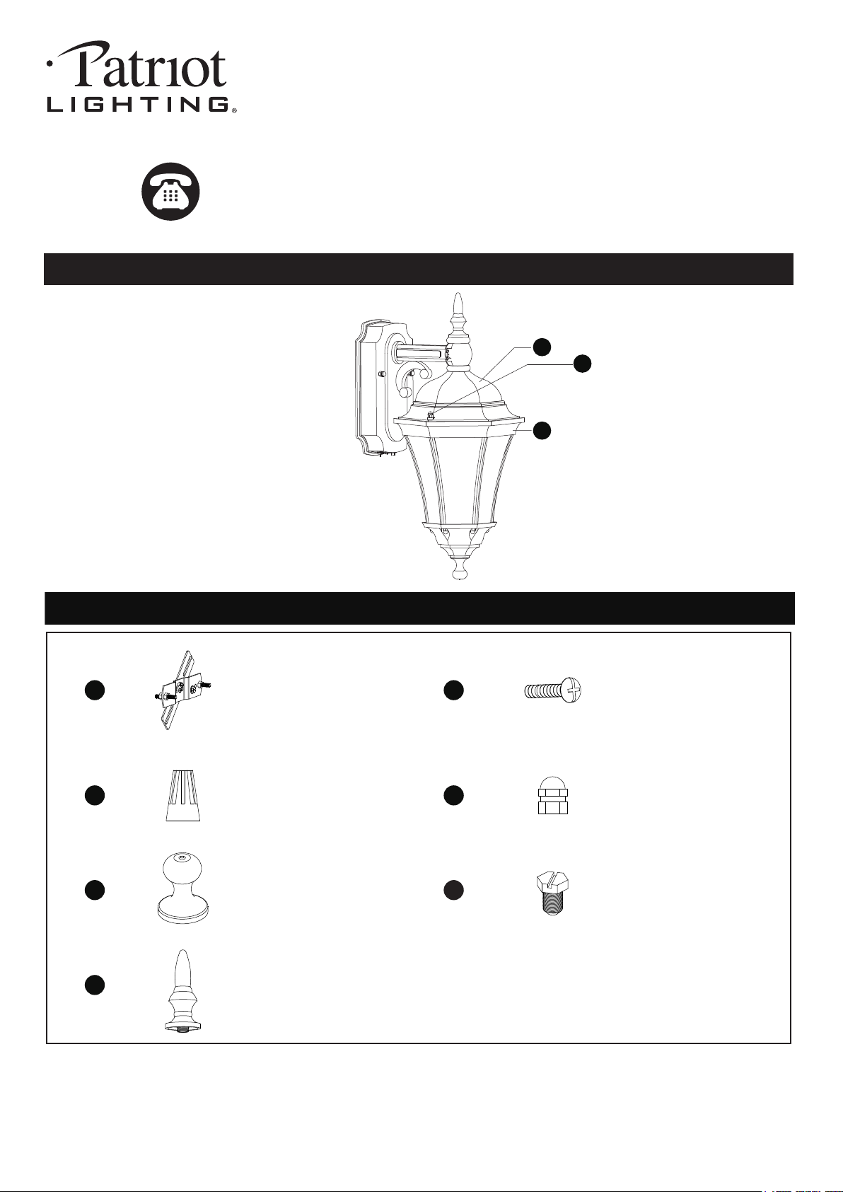
ASSEMBLY INSTRUCTIONS (continued)
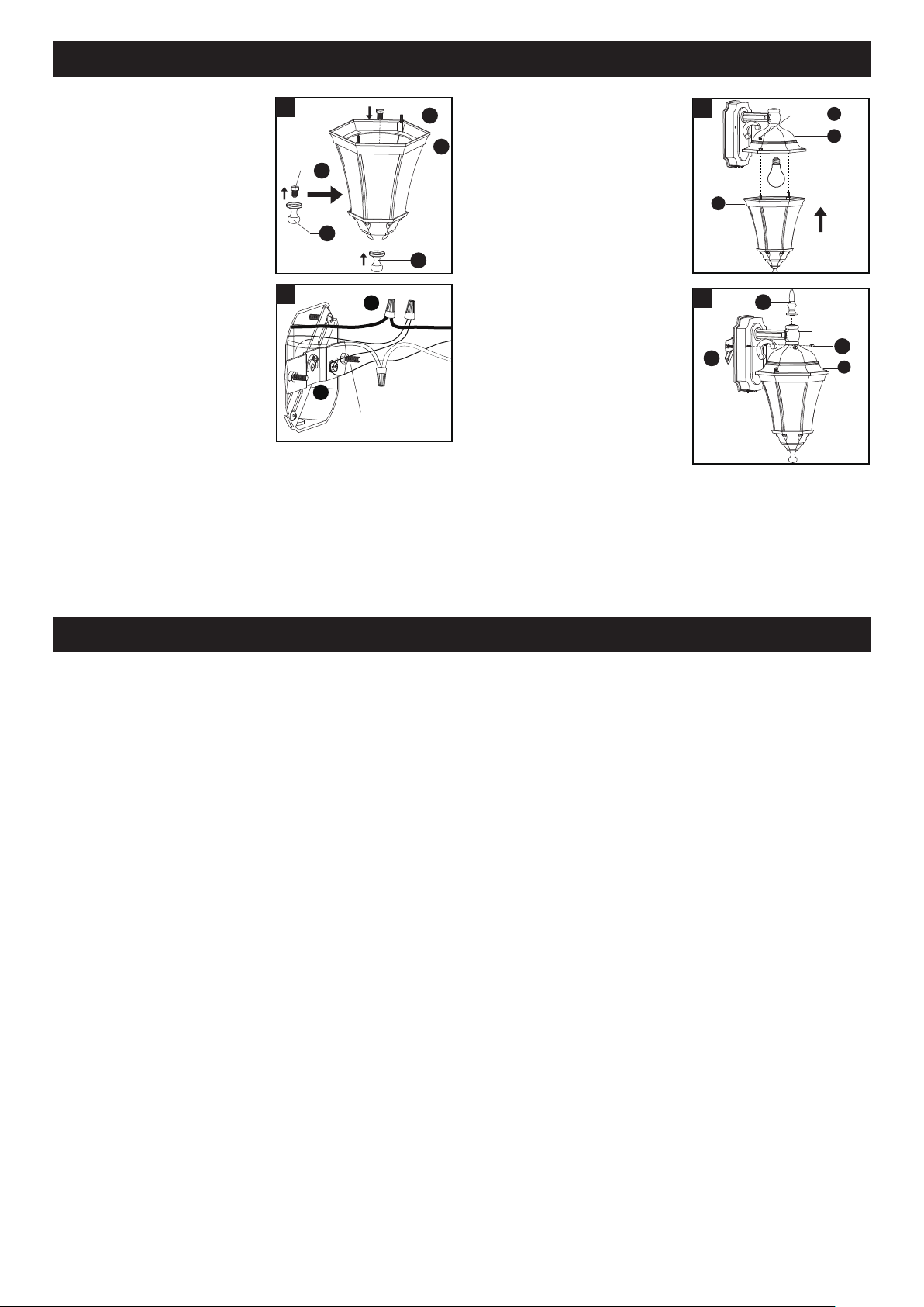
3. Remove the plastic screw
(FF) from the bottom finial
(EE), and then thread the
plastic screw through the
hole of the metal frame (B),
and secure it with the bottom
finial (EE).
EE
EE
FF
FF
B
3
4. Install the bulb (not included).
Attach the metal frame (B)
back to the main fixture (A),
and secure it with two
decorative cap nuts (C).
6. Attach the top finial (GG) to
the top of the sensor lens.
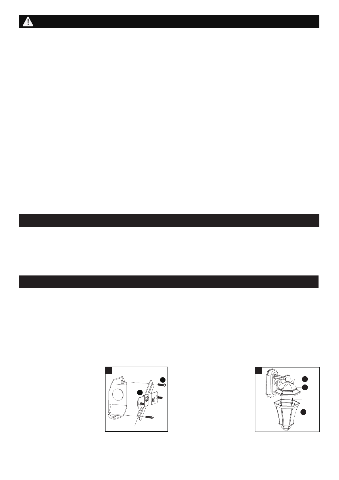
Unscrew the two bolt nuts (DD)
from the cross bar unit (AA).
Attach the backplate of the
main fixture (A) to the cross
bar unit (AA) by aligning and
inserting the two fixture
mounting screws from the
cross bar unit (AA) into the
open holes on the backplate,
then screw the two bolt nuts (DD).
Note: With silicone caulking compound, caulk
completely around where the backplate meets with
the wall surface to prevent water from seeping into
the outlet box.
Turn on the power at fuse or circuit box.
4
B
C
A
Max.100W
Type A Bulb
(not included)
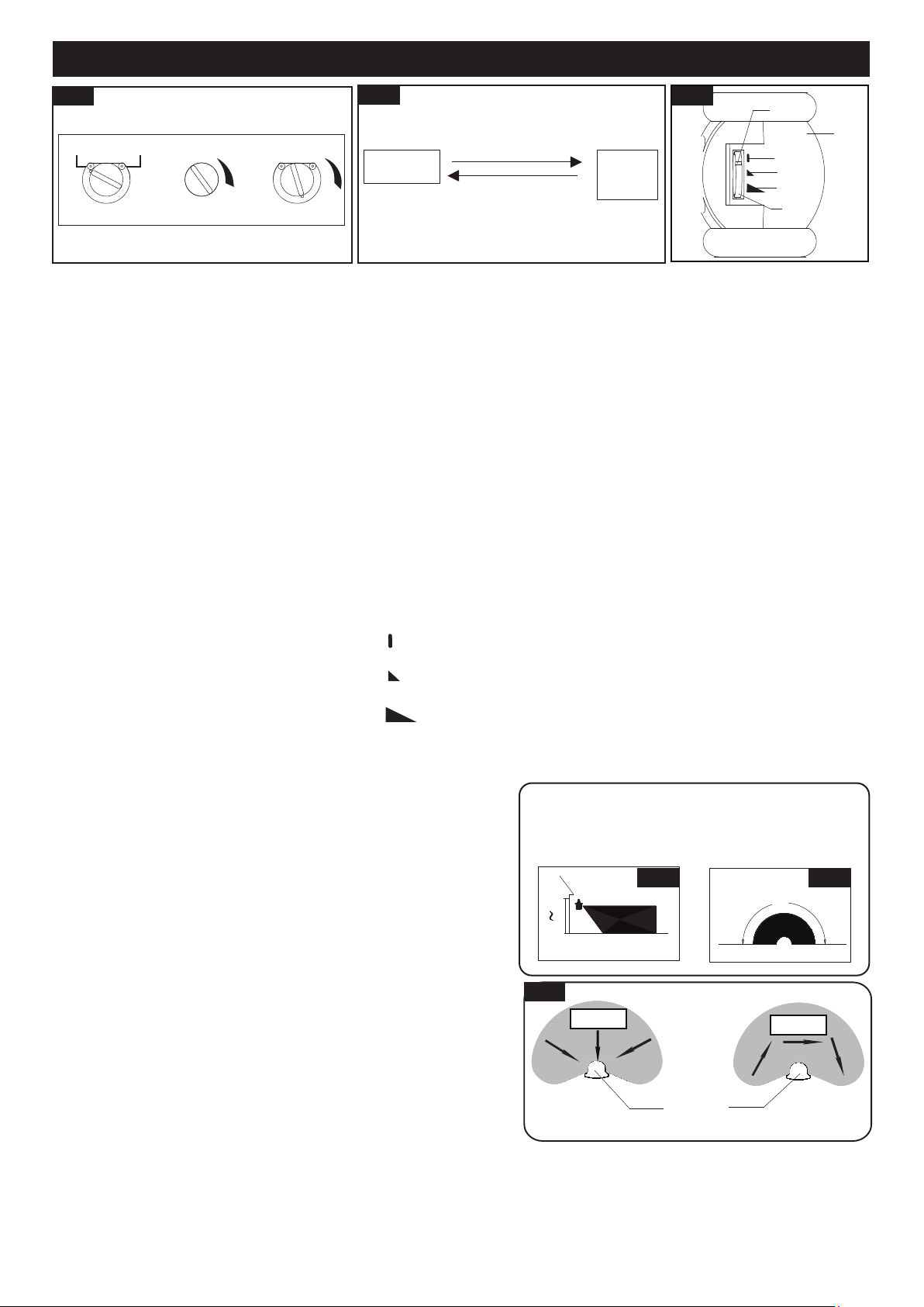
Choose a mode by rotate the knob on the bottom of the back plate. When power is first applied, the light will turn on
immediately. Wait for 15 seconds to allow the sensor to warm up.
1. TEST MODE(daytime or nighttime operation)
●Rotate knob on the bottom of back plate to the “TEST” position.
● When rotate the MODE SELECTOR knob to “SECURITY”, and rotate “TEST/TIME” knob arrow to point to
“TEST”, It is turned off after warming up. It is turned on when the motion is detected, and stayed on as long as
the motion continues. It is turned off about 5~30 seconds after the motion is no longer detected.
● When rotate the MODE SELECTOR knob to “DUSK TO DAWN”, and rotate “TEST/TIME” knob arrow to point to
“TEST”, it is turned on no matter whether the motion is detected or not.
2. DUSK TO DAWN MODE (nighttime operation only)
● To shift to “DUSK TO DAWN” mode, rotate the mode selector knob to “DUSK TO DAWN”, and rotate “TEST/TIME”
knob clockwise by 90° (the photocell is exposed). At dusk the light is turned on automatically, and the light is turned
off automatically at dawn.
3. SECURITY MODE (nighttime operation only)
● To shift to “SECURITY” mode, rotate the mode selector knob to “SECURITY”, and rotate “TEST/TIME” knob
clockwise to point to the desired time setting (between 5 seconds and 10 minutes). At dusk, when motion is
detected, the light is turned on and stayed on as long as motion continues. When the motion is no longer detected,
the light is remained on for the predetermined time you set (5s ~ 10min), and then turned off automatically.
● The light is turned off automatically at dawn.
4. Manual Override Mode (nighttime operation only) (See Fig.2)
● To temporarily override the settings in “SECURITY” mode for continuous on at night, rotate the mode selector knob
to “SECURITY”, and rotate “TEST/TIME” knob clockwise away from “TEST” position, turn the wall switch “OFF”
then turn it “ON” within 1~3 seconds, the light is remained on all night long. To shift back to “SECURITY” mode, turn
the wall switch “OFF”, 5 seconds later, turn it “ON”, the light is reset to initial state, wait for warming up then the
light is reverted back to “SECURITY” mode.
● The light is turned off automatically at dawn.
FUNCTION AND OPERATION
5. Pull out the source wires
from the outlet box. Make
wire connections using wire
connectors (CC) as follows:
• Connect the hot wire
(usually black insulation)
from the fixture to the black
wire from the power source.
• Connect the neutral wire
(usually white insulation) from the fixture to the white
wire from the power source.
• Attach the fixture grounding wire (usually green
insulation or bare wire) to the cross bar unit (AA) with
the green grounding screw. Then, depending on local
code, connect it to the house grounding wire with the
wire connector (CC).
Carefully put all of the wires back into the outlet box.
Green Grounding
Screw
CC
AA
A
DD
AA
GG
6
Fixture
Mounting
Screw
Sensor Lens
200818