Thank you for counting on Metron Value to meet your
medical equipment needs by purchasing this equipment.
All Metron Value equipment is designed and manufactured
to provide years of dependable service because we want
you as a customer now and in the future. Below are easy
to follow instructions on how to properly assemble your
equipment. Please contact us if you experience any
difficulty with the assembly or have questions.
INTENDED USE
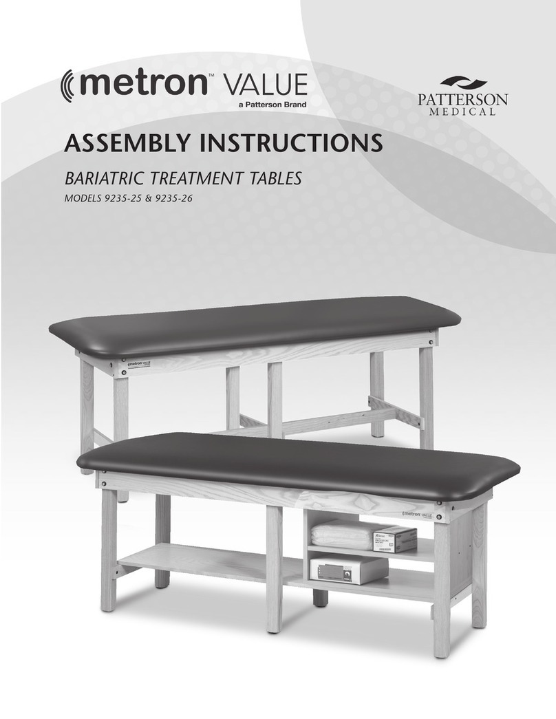
Metron Value treatment tables, models 9235-21 & 9235-22
are specifically designed and engineered for the use by a
single person at a time, who is attended to and observed
by trained medical personnel. Never leave anyone on the
table unattended. Person’s weight and the combination
of force exerted on the table during treatment is not to
exceed a total of 400 lbs.
ASSEMBLY INSTRUCTIONS fOR METRON VALUE TREATMENT TABLES
MODEL 9235-23 with ADJUSTABLE BACKREST
MODEL 9235-23 with NON-ADJUSTABLE TOP/PRE-ATTACHED TOP begin assembly with STEP 4
MAXIMUM WEIGhT CAPACITY 400 LBS
1Place the upholstered sections on a flat surface
with the foot end on the left as shown. Place
the head end on right with hinge toward the
center of the table. Place frame on top with channel, teeth
down, above the head end.
teeth
center hinge
fOR MODELS WITh ADJUSTABLE BACKREST
IF TOP IS ATTACHED TO FRAME, SKIP TO STEP 4
hardware Package
(4) 1/4-20 x 11/2" Black Truss Head Screws (4)
(8) 1/4-20 x 1" Silver Truss Head Screws (0)
(8) 5/16" Washers (4)
(4) 5/16" Nuts (4)
(2) #8 Screws (2)
KD
Quantity
Pre-Attached
Quantity
Tools Required
• Phillips Screwdriver
• Adjustable Wrench
A. Legs
B. Frame
C. Drawer
D. Top
E. Laminate Shelf
F. Spanner
G. H-Braces
H. Tiered Shelf
A
A
A
C
A
A
A
E
F
FE
D
G
G
G
G
H
H
D
B
BC
9235-23
9235-23 with Adjustable Backrest
Time Required
•
20–25 Minutes
Spanner under shelf
Spanner under shelf
2
3
Align the holes in the hinge with the holes in
the center board and fasten to center board
using 4 silver, 1/4-20 x 1" truss head screws.
Finger tighten the top's foot end to frame using
4 silver, 1/4-20 x 1" truss head screws and 5/16"
washers. Slide the foot end toward the center
board and finish tightening screws.
fOR MODELS WITh ADJUSTABLE BACKREST
fOR MODELS WITh ADJUSTABLE BACKREST
ShELf ASSEMBLY
Remove drawer and invert the table to an
upright position on all four legs, using caution
when inverting the end with the adjustable headrest. Apply
4 adhesive backed hook strips to top edge of H-braces.
Place the full-length shelf on the spanner with the loop side
over the hook strips on the braces. Reinsert the drawer.
6
7
8
5
4
Position the H-brace with finished edge toward
top with the cut-out slot facing toward the
inside of the table and attach using the 4 black
1/4-20 x 11/2" truss head screws.
Position the spanner finished edge towards top
and align the hole in the center of the spanner
with the hole in the H-brace and finger tighten
on one end then repeat on the opposite end using the #8
screws. Finish by tightening both ends. DO NOT OVER
TIGhTEN.
Return to each corner leg and finish
tightening each nut. DO NOT OVER
TIGhTEN.
Position leg in the leg brace with H-brace hole
facing inward. Attach the leg using 5/16" washer
and 5/16" nut. Finger tighten nut now, and fully
tighten after step 6 is completed. Repeat with remaining
legs.
Adhesive backed hook strips

