PCE Health and Fitness GLB Wallbox User manual
PCE Wallbox GLB
Manual 380226-4.1
Quickstart guide installation of standalone GLB Wallbox

TABLE OF CONTENTS
WARNINGS 3
INSTALLATION OF STANDALONE GLB WALLBOX 10
NORMAL USE / CHARGING 11
BASIC LED INDICATIONS 11
SOFTWARE GLB 11
SERVICE/MAINTENANCE 11
TROUBLESHOOTING/SUPPORT/FAQ 11
TECHNICAL SPECIFICATIONS 12
HANDOVER REPORT 13
WARRANTY CONDITIONS 14
2
DEEN
WARNINGS
Do not use private power generators as a power source
for charging.
Incorrect installation and testing of the GLB Wallbox could
potentially damage either the vehicle’s battery and/or the
GLB Wallbox itself.
Do not operate the GLB Wallbox in temperatures outside
its operating range – see technical specificatrions.
All installation must be carried out by an authorised
installer and comply with local installation regulations.
If any questions, please contact your local electrical
authority.
Ensure that the GLB Wallbox’s charging cable is
positioned so it will not be stepped on, driven over,
tripped on, or subjected to damage or stress.
Unroll the charging cable to prevent it from overheating.
Do not use cleaning solvents to clean any of the GLB
Wallbox’s components. The outside of the GLB Wallbox,
the charging cable, and the end of the charging cable
should be periodically wiped with a clean, dry cloth to
remove accumulation of dirt and dust.
Be careful not to damage the circuit boards or components
during installation.
Refer to local standards and regulations not to exceed
charging current limitations.
The front cover must always be locked in its upper position
in order to ensure compliance with IP Code IP44.
Avoid to install the GLB Wallbox in direct sunlight to avoid
any heat-problems.
To even out the load, it is important to rotate the phases
when connecting several of GLB Wallboxes to the same
system. Note that 1-phase charging is common in electric
vehicles and L1 in the GLB is used for this purpose.
Ventilation signal from EV is not supported.
Adapters for charging connectors are not allowed to be
used.
Cord extension sets for charging cable is not allowed to
be used.
Dielectric Voltage Withstand Test is not allowed on GLB
Wallbox.
This equipment should not be used by anyone (including
children) with reduced physical, sensory or mental
capacity, or anyone lacking in experience or knowledge,
unless they are provided with supervision or prior
instruction in how to use the equipment by the person
responsible for their safety.
The GLB Wallbox range of charging stations is designed
exclusively for charging electric vehicles.
The GLB Wallbox must be grounded according to local
country installation requirements.
Do not install or use the GLB Wallbox near flammable,
explosive, harsh, or combustible materials, chemicals, or
vapors.
Turn off the electrical power at the circuit breaker before
installing, configuring or cleaning of the GLB Wallbox.
Use the GLB Wallbox only within the specified
parameters.
Never spray water or any other liquid directly at the GLB
Wallbox. Never spray any liquid onto the charge handle
or submerge the charge handle in liquid. Store the charge
handle in the dock to prevent unnecessary exposure to
contamination or moisture.
Do not use this equipment if it appears to be damaged or
if the charging cable appears to be damaged.
Do not modify the equipment installation or any part of the
product.
Do not touch the GLB Wallbox’s end terminals with fingers
or any other objects.
Do not insert foreign objects into any part of the GLB
Wallbox.
This document contains general descriptions which are verified to
be accurate at the time of printing. However, because continuous
improvement is a goal at PCE, we reserve the right to make
product and software modifications at any time.
Latest manual can always be found at www.pcelectric.at/de/
info/emobility.html
2 3
DEEN
2
3
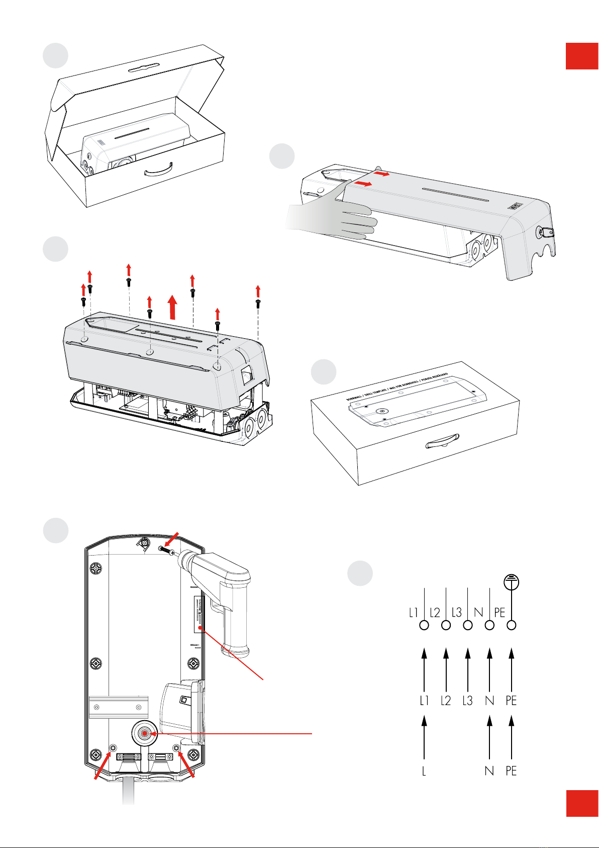
(7 x T20)
1
4
5
6
Signal cable entrance
CU
Serial no./SSID password
TERMINAL BLOCK
3-phase
1-phase
AL
Drill template
(see the back of the box)
4
EN
ON OFF
SW2
ON
3
2
1
6
5
4
SW1
OFF
SW1
7
8
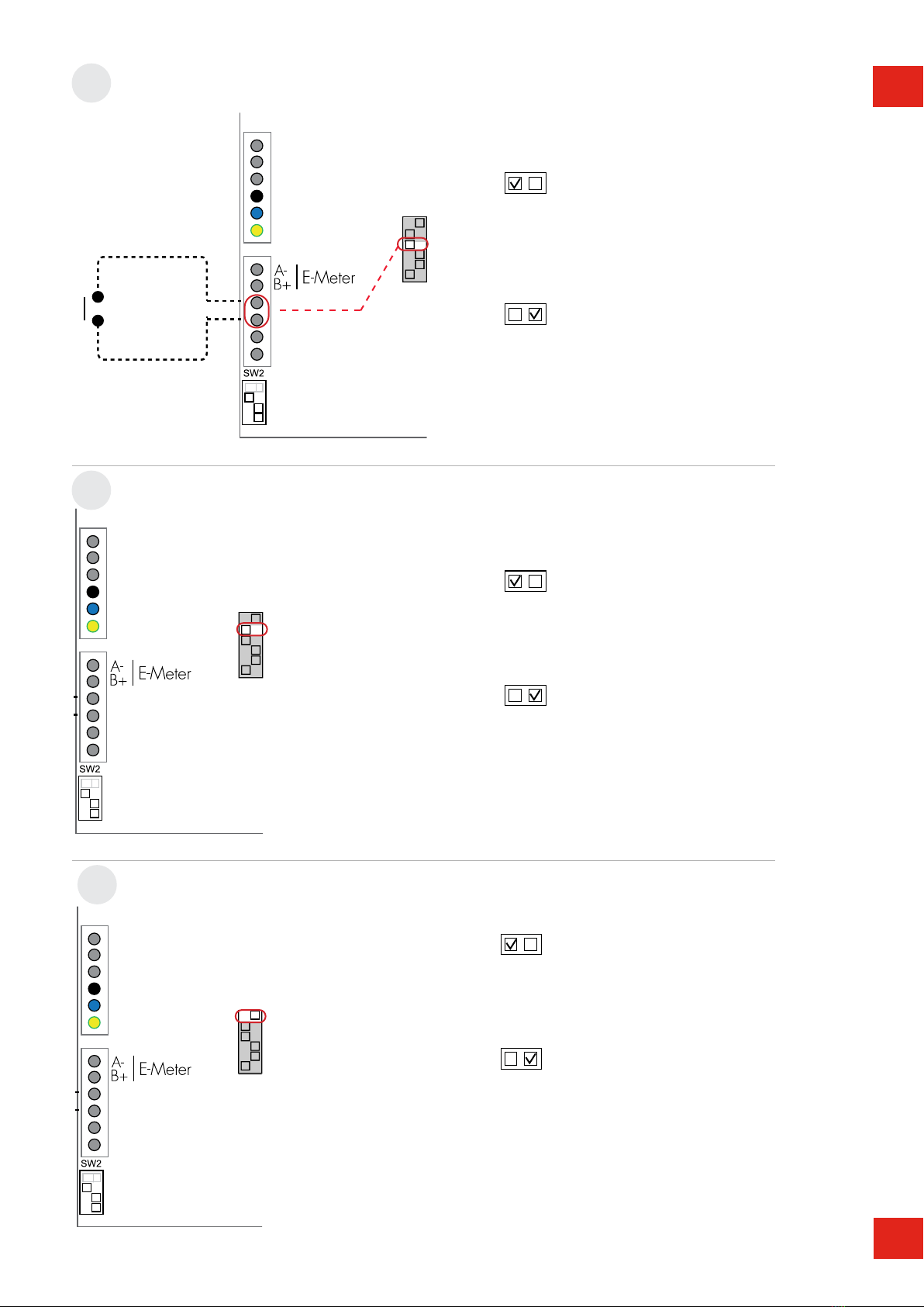
DLM-Meter
Adr.2
Install the DLM meter in the mains cabinet you want to
monitor. Use shielded twisted pair cable between the DLM
meter and the wallbox.
Suitable cables:
CAT5 FTP, CAT5e FTP, CAT6 FTP, ELAKY-S, ELAQBY-S or
similar.
For full DLM manual and settings:
www.pcelectric.at/de/info/emobility.html
SET FUSE SIZE IN MAINS CABINET (FOR A WALLBOX)
OPTIONS
DLM METER INSTALLATION (ACCESSORY)
4 5
DEEN
OFF
4
5
ON
SW1
4
6
SW1
OFF
4
ON
OFF
5
ON
OFF
5
ON
OFF
6
ON
OFF
6
ON
9
10
11
ON (default): Use
when not connected to
external enable relay.
OFF: Use when
connected to external
enable relay.
REMOTE ENABLE SETTING OF A WALLBOX
MASTER / SLAVE SETTINGS
SW1
Stand allone installation = ON
Cluster installation = See Full manual at
www.pcelectric.at/de/info/emobility.
html
DATALINK END TERMINATION SETTINGS (N/A FOR STAND ALONE INSTALLATION)
ON (default): Master
OFF: Slave
No function for stand alone installation. Only for
cluster installation via Datalink Cluster installation
= See Full Guide at www.pcelectric.at/de/info/
emobility.html
ON: Datalink end termination resistor active.
OFF (default): Datalink end
termination resistor not active.
external enable relay
6
DEEN
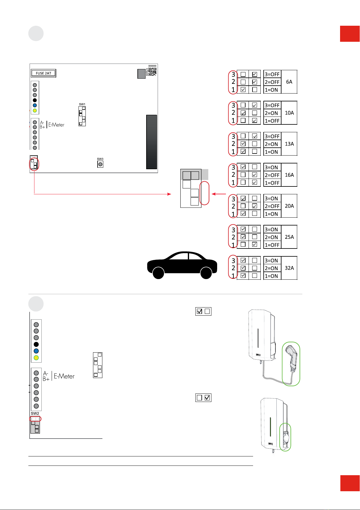
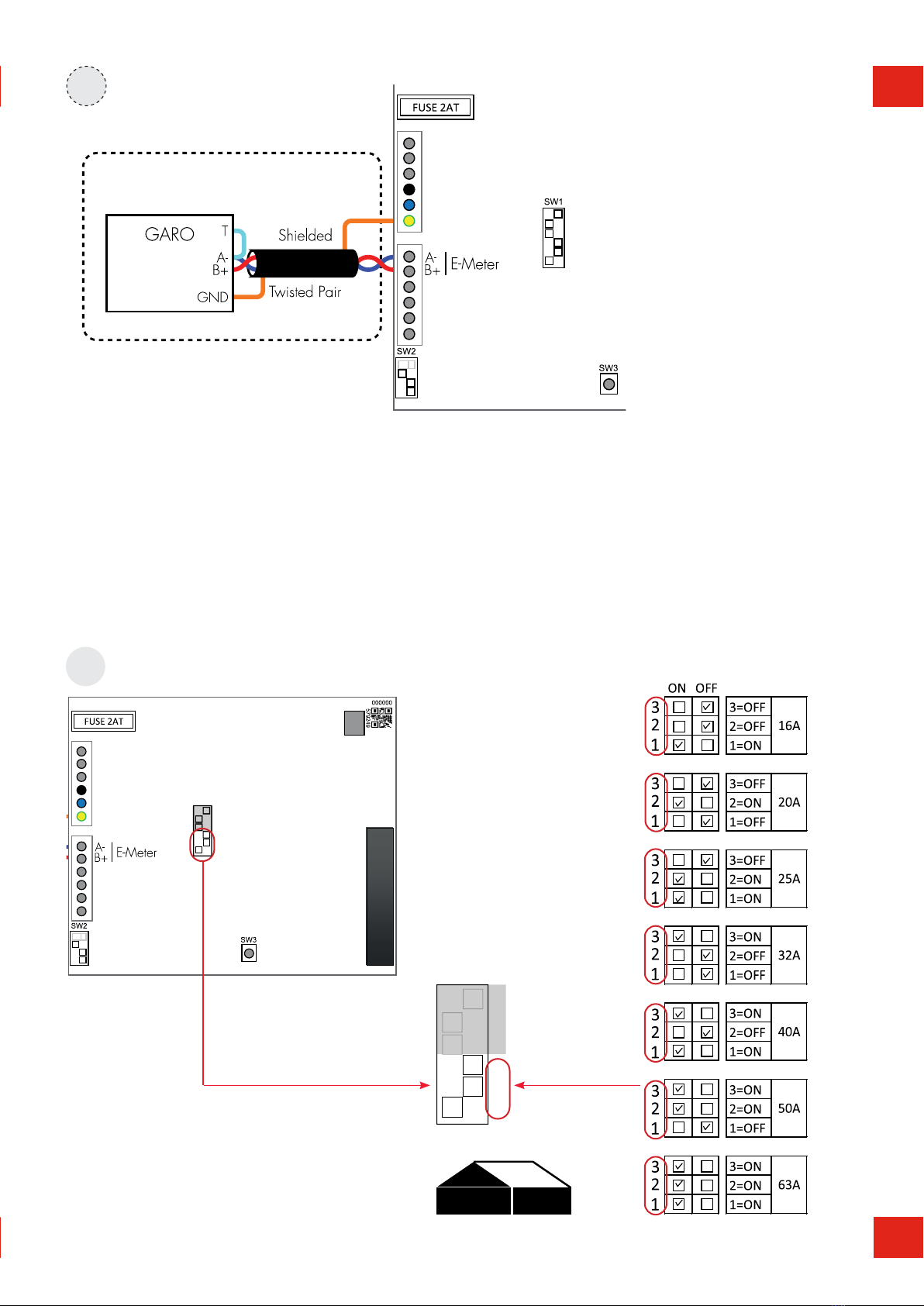
Main fuse 16A 20A 25A 32A 40A 50A 63A
SW1(DIP 1-3) 16A 20A 25A 32A 40A 50A 63A
SW2(DIP 1-3) 13A 16A 20A 25A 32A 32A 32A
ON OFF
SW2
3
2
1
4
4
ON OFF
SW2
4
SW1
OFF
4
ON
OFF
4
ON
12
13
DIP-SWITCH 2
MAX VEHICLE CHARGING CURRENT (A)
WALLBOX TYPE ON: Fixed cable
OFF: Outlet
7
EN
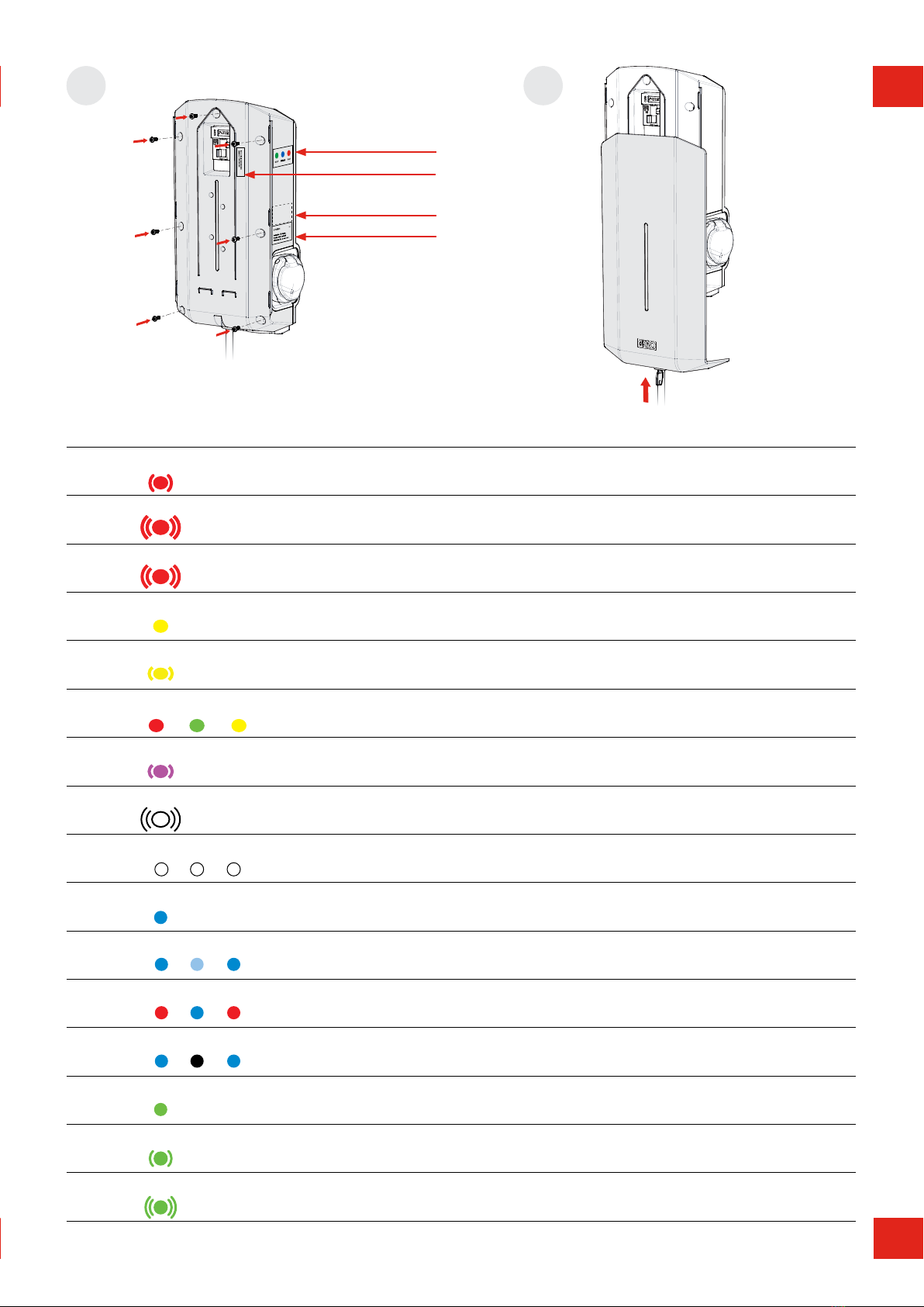
14 15
(7 x T20)
MAX 1,6 Nm
language label is
placed on the side
label explaining charger
status indication
english information label
TROUBLESHOOTING / INFORMATION
INDICATION TYPE OF FAULT MEASURE
Solid red light RCCB has tripped or EV earth check
error is detected.
Reset. Refer to section on resetting the residual-
current or personal protective current breaker.
Solid red light for 3 sec RFID card not accepted. Check RFID card
Red fast flash light DC current >6mA - charging has
stopped.
Solid yellow light Broken cable. Check charging cable
Yellow flash light Motor lock socket not in latched
position.
Contact a qualified electrician.
Shifting red/green/yellow light DC detection hardware error.
Purple flash light Chargebox overheating, charging has
stopped.
After cool down, the charging process is restarted
automatically.
White fast flash light Search light indication. Comparison with complete operating instructions
One quick white flash light repeating
every minute
Indicate an error in DLM function. Auto reset occurs as soon as the connection to the
energy meter is re-established.
Solid blue light RFID accepted - waiting to start
charging.
Shifting blue light intensity EV charging in progress.
Shifting red/blue light Software upgrade in progress.
Shifting blue/black light Chargesession not enabled due to
scheduled mood.
Solid green light Charger in idle, waiting for EV to
connect.
Green flash light EV connected, wait to start charging or
EV has finish charging.
Green fast flash light RFID reader is active, waiting to read
card for authorization.
Serial No / SSID
8
DE
7
EN
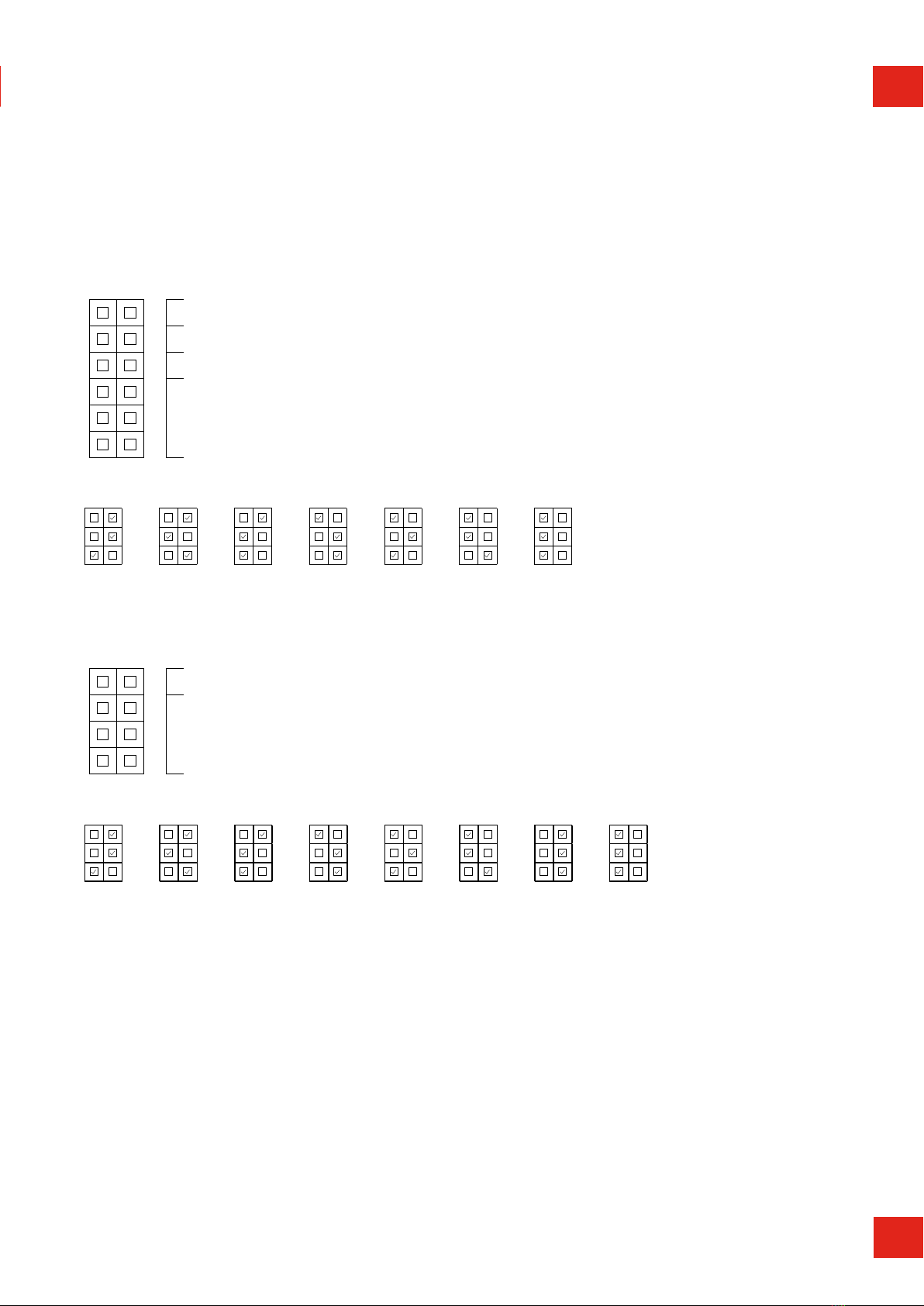
ON OFF ON OFF ON OFF ON OFF ON OFF ON OFF ON OFF ON OFF
33 3 3 3 3 3 3
2 2 2 2 2 2 2 2
1 1 1 1 1 1 1 1
6 A 10 A 13 A 16 A 20 A 25 A 29 A 32 A
DIP-SWITCH INFORMATION
SW1
ON OFF
66 Datalink Endtermination ON, OFF
55 ON = Master Mode, OFF = Slave mode
44 Remote enable input function. ON (default) = Open circuit, OFF = Closed circuit
33
22 Fuse value in mains cabinet, see below table for settings
11
ON OFF ON OFF ON OFF ON OFF ON OFF ON OFF ON OFF
33 3 3 3 3 3
2 2 2 2 2 2 2
1 1 1 1 1 1 1
16 A 20 A 25 A 32 A 40 A 50 A 63 A
SW2
ON OFF
44 ON = Fixed cable, OFF = Outlet
33
22 MAX Ampere for outlet / cable, see below table for settings
11
ON OFF ON OFF ON OFF ON OFF ON OFF ON OFF ON OFF ON OFF
33 3 3 3 3 3 3
2 2 2 2 2 2 2 2
1 1 1 1 1 1 1 1
6 A 10 A 13 A 16 A 20 A 25 A 29 A 32 A
9
DEEN

(for installation of GLB in cluster, see User manual at www.
pcelectric.at/de/info/emobility.html
1) GLB Wallbox without RCCB or RCBO included in the
enclosure must have Residual Current protection and
must be protected with a max 32A fuse in the supply
distribution box.
2) GLB Wallbox without RCCB Type B fitted or DC fault
protection in the enclosure must in accordance to IEC
60364-7-722 be protected with a Residual Current
Device (RCD) Type B.
3) 3-phase GLB Wallbox equipped with a Residual Current
Circuit Breaker (RCCB) must be protected with a max
32A fuse in the supply distribution box.
4) 1-phase GLB Wallbox fitted with a Residual Current
Breaker with Overcurrent Protection (RCBO) can be
connected in parallel. This group of chargers must be
protected by a backup fuse in the distribution box. The
backup fuse shall not exceed 125A.
GLB Type
Protection type
1-phase
3-phase
No RCBO or RCCB
RCBO
RCCB type A
RCCB type B
DC-fault protection
GLB..-..37.. 2) 4)
GLB..-..74.. 2) 4)
GLB..-..22.. 1) 2)
GLB..-..22..-A 2) 3)
GLB..-..22..-B 3)
GLBDC..-..37.. 4)
GLBDC..-..74.. 4)
GLBDC..-..11.. 1)
GLBDC..-..22.. 1)
GLBDC..-..22..-A 3)
1. Select the appropriate group fuse (1x6A - 3x32A) and
cable area for the electrical installation. Some countries
require earth fault breakers to be installed. Follow local
country regulations and select the appropriate earth fault
equipment for the electrical installation. NOTE! Due to
high currents for a long time in the cable, there is a high
risk of voltage drop if the cable is under-dimensioned
which can damage the electronics in an EV.
2. Fill in the information in the handover report.
3. Mount the GLB Wallbox according to the installation
sketch, (figure 1-7)
4. Install the electrical power supply cable according to local
regulations.
5. Set dip switch SW1 to same (A) as the main fuse (16-
63A). SW1 is located at the center left hand side of the
main board. See figure 8-11.
6. Set the dip switch SW2 according to your group fuse
for the GLB Wallbox ( 6-32A). Dip switch 2 is located at
bottom left corner of the main board. See figure 12-13.
7. Fill in serial number in the handover report. See figure 14,
Serial No / SSID label.
8. Mount the box cover on the enclosure + front lid, see
figure 14-15.
9. Turn on the electrical power to the GLB Wallbox.
10. For GLBW… and GLBDCW… models: Connect a mobile
device (PC/Tablet/Mobile) to the GLB Wallbox Wifi
network. You find SSID and password on the rating label.
Type in 172.24.1.1 in your web browser and check
that the GLB webinterface is visible. This action confirms
that the GLB Wallbox communication module is working
properly.
11. Test the charger with a test instrument or test to charge
an electric vehicle to ensure that the charger is working
properly.
12. Doublecheck that the handover report is filled in
completely, sign with name, date and company that the
warranty is valid.
INSTALLATION OF STANDALONE GLB WALLBOX
10
DEEN

NORMAL USE / CHARGING
Connect the charging cable to the EV. Charging will start instant if
the EV is ready for charging.
See your EV charging manual.
When finishing charging, follow the car’s instructions.
After charging: Release the charging cable from your EV and
place the charging cable at designated place.
BASIC LED INDICATIONS
GLB-SOFTWARE
SERVICE/MAINTENANCE
TROUBLESHOOTING/SUPPORT/FAQ
See User manual at www.pcelectric.at/de/info/emobility.html
Solid green light: ready for charging
Green flash light: GLB Wallbox waiting for
start signal from electric vehicle
Shifting blue light intensity: charging
Other LED indications: see User manual at
www.pcelectric.at/de/info/emobility.html
11
DEEN

TECHNICAL SPECIFICATIONS
Product type All GLB models
Standards / Directives IEC 61851-1 and IEC 61439-7
EMC Classification: 2014/30/EU
Installation method: Wall
Installation environment: Indoor / Outdoor
Location type: Non-restricted Access
Rated Voltage: 230V / 400V 50Hz
Installation systems: TT, TN and IT systems
Charging type: Mode 3
Charging method: AC
Protection class: IP44
Mechanical impact resistance: IK08
Temperature range: -25C - +40C
Weight: 3-5,4 kg (depending on model)
Standard cable length (fixed cable
version):
Standard 4,5m
Rated current withstand 10kA
Rated short-time withstand current 10kA
Rated conditional short-circuit current
of an assembly
10kA
Short-circuit protective device type Type C
Rated impulse withstand voltage 4kV
Rated insulation voltage 230/400V
Rated current of each circuit 32A
Standby power 6W
Rated diversity factor RDF=1
Pollution degree: 3
EMC environmental condition A and B
12
DEEN
HANDOVER REPORT
Charging device for electric vehicles (EV)
Version 07/2021
PC Electric Ges.m.b.H. I Diesseits 145, 4973 St. Martin i. I. I AUSTRIA I 📞+43 7751 61220 I [email protected] I www.pcelectric.at
Authorised Electrician
Company Name:
Street:
Zip code/Place:
Name of electrician:
Sagnature:
Client
Name:
Street:
Zip code/Place:
Sagnature:
Place, date:
Modell
GLB: GTB:
Serial No: Software version:
RFID-Reader: yes no Communication Module: yes no
Electrical installation
Group Fuse (A):
Supply line: Cable dimension: Cable length:
Settings DIP-Switch
Mark existing
position:
SW1
ON OFF
6
5
4
3
2
1
SW2
ON OFF
4
3
2
1
Function test performed with:
EV test adapter: Electrical vehicle (EV):
Notes/Others
1
3
4
7
5
89
Location
Street: Zip code/Place:
Exact placement: (e.g.: carport, garage, outdoors, ...)
2
All installation must be performed by a qualied electrician in accordance with local installation regulations. If you have any questions, contact your local regulatory authority.
A
Load management settings (DLM)
Against building: In the supply line:
Meter adressing: 2 100/101
Total current (A):
6
13
DEEN

WARRANTY CONDITIONS
1. The product benefits from manufacturer´s warranty. The applicable warranty period must be
stated in purchase documents from your supplier.
2. The product must be installed by a certified installer / contractor.
3. Proper installation, storage and operation conditions must be obtained.
4. Warranties apply only to products installed in their original installation location.
5. Installation, use, care, and maintenance must be normal and in accordance with instructions.
6. Warranty requires a dated, fully filled in handover report by an certified installer/contractor.
If the original installation date cannot be verified, then the warranty period begins ninety (90)
days from the date of product manufacture (as indicated by the model and serial number).
7. Warranty does not cover damage occurred by incorrect use of equipment, use of any non-
original spare parts, lack of maintenance or faults caused by disassembly of the product or
unauthorized persons intervention.
8. Warranty does not cover software or update thereof.
9. Warranty does not cover aesthetic deficiencies caused by negligent manipulation or
accidents (breaks or damage to the carcass).
10. Warranty does not cover damage caused by external overvoltage from either grid or car/
charging object.
11. Warranty does not cover damage caused by force major like for example but not limited
to: floods, winds, fires, lightning, accidents, sabotage, military conflicts, terrorism, volcanos,
earthquakes or corrosive environments.
NOTICE!
Completely filled out handover report required.
The warranty does not apply if the product has been subjected to an insulation test.
EU COUNTRIES (EXCEPT SWEDEN)
14
DEEN

IK08
PC Electric GmbH
Diesseits 145, AT–4973 St. Martin i. I.
Tel.: +43 (0) 7751 61220
Fax: +43 (0) 7751 6969
www.pcelectric.at
GARO AB
Box 203, SE–335 25 Gnosjö
Tel.: +46 (0) 370 33 28 00
Fax: +46 (0) 370 33 28 50
garo.se
Distribution:Manufacturer:
Table of contents
Other PCE Health and Fitness Batteries Charger manuals


