Det är VIKTIGT att försäkra sig om att tappen
möter kolven rakt. Lyft och sänk locket och se
till att du kan höra mikrobrytaren fungera. Det
kan vara nödvändigt att böja tappen något för att
säkerställa korrekt funktion.
Remskivorna kan nu monteras. Observera att de
inte är utbytbara. Motoraxelremskivan är placerad
med en nyckel och en fjädrande tryckskruv, och
ett kilspår är därför förberett i borrningen, medan
växellådans remskiva inte har något kilspår och är
belägen med en fjädrande tryckskruv på en platta
fräst i axeln.
VIKTIGT. Vid montering, se till att den motor eller
drivhjul med minsta diameter driver den växellåda
eller bladskiva med störst diameter, dvs de är
monterade omvänt mot varandra. Det är normalt att
montera drivhjulet med minsta diameter inåt och
växellådans remskiva med minsta diameter utåt
(som illustreras i deldiagrammet, Fig 3, sida 6).
Placera växellådans remskiva på sin axel, se till att
tryckskruven hamnar i linje med plattan på axeln.
Dra åt tryckskruven helt. Montera motorskivan på
axeln så att den hamnar i linje med växellådans
remskiva. Detta kan göras med en rak kant över
remskivans topp för att säkerställa att spåren är i
linje. Vid korrekt inriktning, dra åt den medföljande
tryckskruven.
Observera att motorn svänger runt dess fästen.
För att passa in drivremmen lyfter du motorn
och låter remmen glida över remskivorna.
Remspänning utförs med hjälp av en bult genom
motorns monteringsplatta. Skruva fast bulten "in"
tills remmen kan tryckas ned ca 1,3cm i mitten.
Lås justerskruven med hjälp av den medföljande
låsmuttern.
VIKTIG. Överdra inte justeringsbulten eftersom det
kommer att förvrida motorns monteringsplatta.
Arbetsstoppmontering:
Ett arbetsstopp (Fig. 1, punkt 7) medföljer, vilket
används för att låta arbetsstycken av samma
längd skäras utan att man behöver mäta varje
stycke individuellt. Den består av två delar,
arbetsstoppet och monteringsstången. Skjut
stången i hålet i städets kant och säkra med
medföljande tryckskruv. Montera arbetsstoppet på
stången, med det platta riktat mot sågklingan och
säkra tillfälligt med den medföljande tryckskruven,
se till att den inte trycks in för långt, eftersom det
kan störa sågklingan när den sänks.
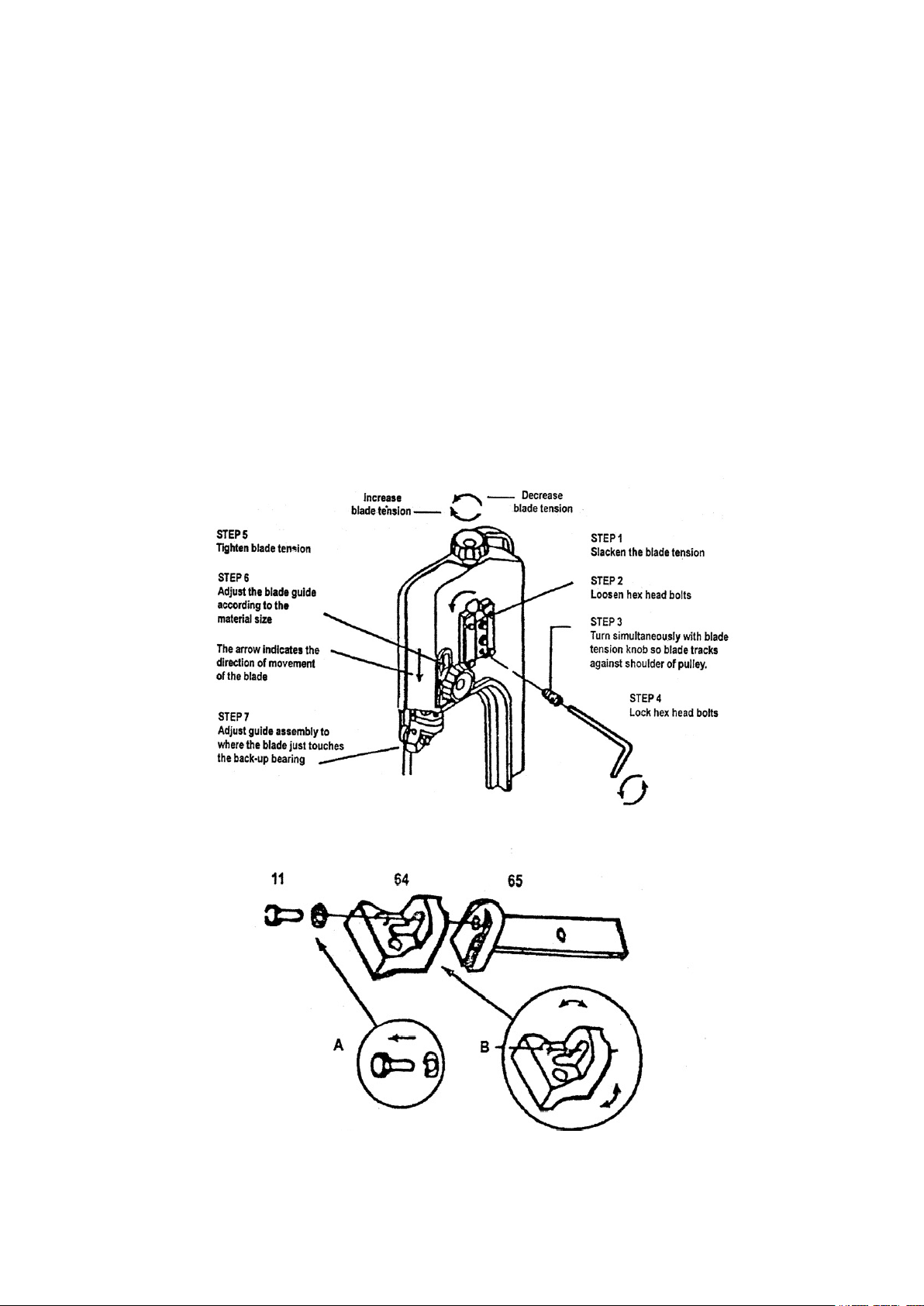
Justering av sågbladsstyrningen:
Metallbandsågen är utrustad med två justerbara
bladstyrningsaggregat (gur 1, punkt 8). Med den
här funktionen kan du justera bladstyrningarnas
position för olika bredder av arbetsstycken.
Bör justeras för att förbereda för det stycke som
ska skäras. Detta görs enligt följande:
1. Placera arbetsstycket i städet på bandsågen
och kläm fast. ·
2. Justera fästbladets styrenhet till önskat läge
genom att lossa handskruvar och positionera
styrningarna efter behov.
3. Dra åt handskruvarna.
Justering av sågbladsstyrningens lager:
Detta är den viktigaste justeringen på din såg. Det
är omöjligt att få tillfredsställande prestanda från
din såg om bladstyrningarna inte är rätt inställda.
Bladstyrningens lager för din metallbandsåg har
justerats och testats med era provskär innan
den lämnar fabriken för att säkerställa korrekt
inställning. Behovet av justering bör sällan ske
om sågen används korrekt. Om guiderna ändå går
ur justering är det extremt viktigt att omedelbart
justera. Om korrekt justering inte upprätthålls, skär
inte bladet rakt och om situationen inte korrigeras
kommer det att orsaka skador på bladet.
Eftersom styrjustering är en kritisk faktor vid
prestanda för sågen är det alltid bäst att prova ett
nytt blad för att se om det här kommer att korri-
gera dålig skärning innan du börjar justera lagren.
Om ett blad blir matt på ena sidan tidigare än det
andra, börjar det till exempel skära krokigt. Ett
enkelt klingbyte bör korrigera detta problem - ett
svårare behov av styrjustering kommer inte att
göra det.
Om ett nytt blad inte löser problemet, kontrollera
bladstyrningarna för korrekt avstånd. Det ska
nnas 0,0025cm frigång mellan 0,06cm tjockt
blad och styrlager. För att få denna frigång justera
enligt följande (se Fig 4, steg 7):