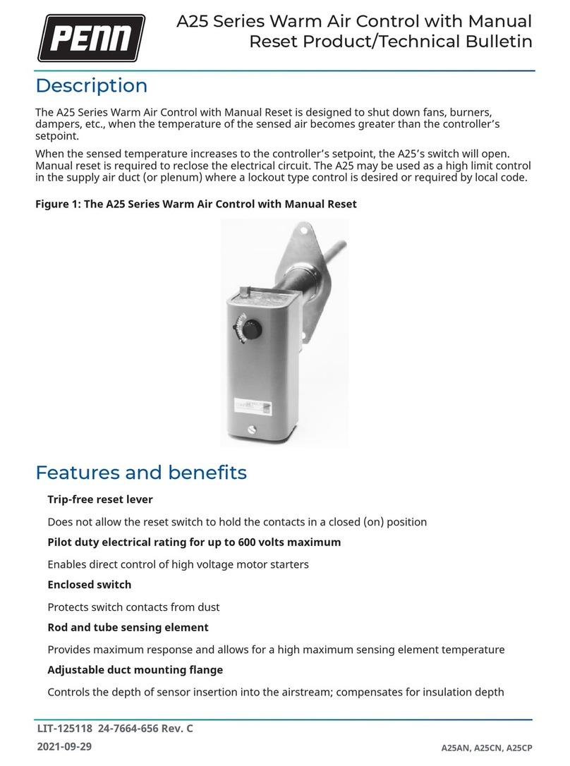
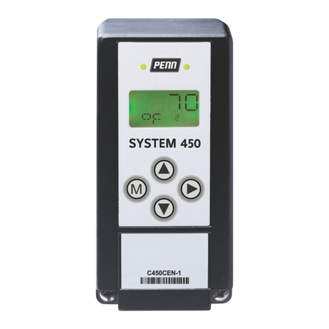
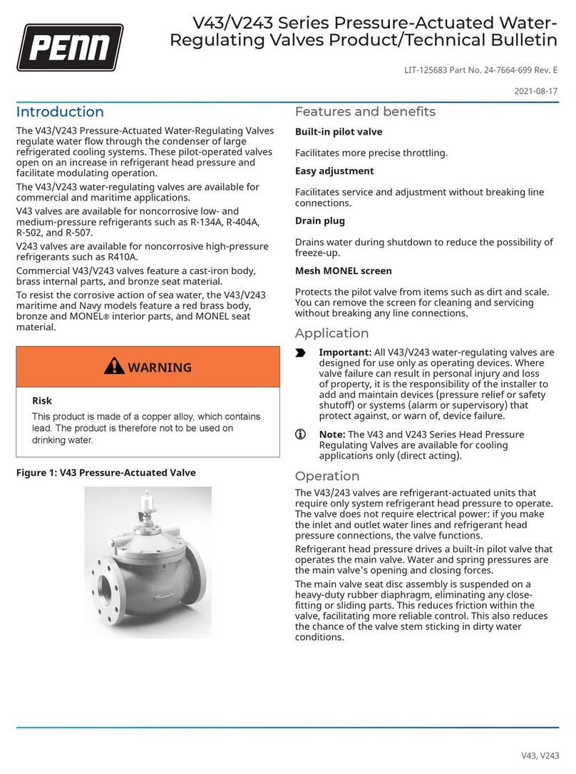
Penn System 450 Series Service manual

Refer to the QuickLIT website for the most up-to-date version of this document.
1
System 450™ Series Modular Control Systems with Standard Control
Modules Technical Bulletin
Document Introduction. . . . . . . . . . . . . . . . . . . . . . . . . . . . . . . . . . . . . . . . . . . . . . . . . 3
System 450 Overview . . . . . . . . . . . . . . . . . . . . . . . . . . . . . . . . . . . . . . . . . . . . . . . . . . 3
System 450 Control Systems with Standard Control Modules . . . . . . . . . . . . . . . . . . . . 4
Control Module and User Interface . . . . . . . . . . . . . . . . . . . . . . . . . . . . . . . . . . . . . . . . . . 5
Expansion Modules, Module Assemblies, and Outputs . . . . . . . . . . . . . . . . . . . . . . . . . 7
Hybrid Analog Output . . . . . . . . . . . . . . . . . . . . . . . . . . . . . . . . . . . . . . . . . . . . . . . . . . . . . 9
System 450 Compatible Sensors and Transducers . . . . . . . . . . . . . . . . . . . . . . . . . . . . 10
High Input Signal Selection . . . . . . . . . . . . . . . . . . . . . . . . . . . . . . . . . . . . . . . . . . . . . . . 23
Differential Control . . . . . . . . . . . . . . . . . . . . . . . . . . . . . . . . . . . . . . . . . . . . . . . . . . . . . . 24
System 450 Control System Examples . . . . . . . . . . . . . . . . . . . . . . . . . . . . . . . . . . . . . . 25
Detailed Procedures . . . . . . . . . . . . . . . . . . . . . . . . . . . . . . . . . . . . . . . . . . . . . . . . . . 34
Designing and Building System 450 Control Systems . . . . . . . . . . . . . . . . . . . . . . . . . 34
Installing System 450 Components. . . . . . . . . . . . . . . . . . . . . . . . . . . . . . . . . . . . . . 35
Wiring System 450 Components . . . . . . . . . . . . . . . . . . . . . . . . . . . . . . . . . . . . . . . . . . . 36
Setting up a System 450 Control System . . . . . . . . . . . . . . . . . . . . . . . . . . . . . . . . . . . . 40
Setting up Control System Outputs. . . . . . . . . . . . . . . . . . . . . . . . . . . . . . . . . . . . . . . . . 45
Determining the Integration Constant for an Analog Output . . . . . . . . . . . . . . . . . . . . 51
Troubleshooting System 450 Control Systems . . . . . . . . . . . . . . . . . . . . . . . . . . . . 54
Specified Voltage Ranges for Sensors . . . . . . . . . . . . . . . . . . . . . . . . . . . . . . . . . . . . . . 54
Repair and Ordering Information. . . . . . . . . . . . . . . . . . . . . . . . . . . . . . . . . . . . . . . . 55
Related Documentation . . . . . . . . . . . . . . . . . . . . . . . . . . . . . . . . . . . . . . . . . . . . . . . 61
Technical Specifications . . . . . . . . . . . . . . . . . . . . . . . . . . . . . . . . . . . . . . . . . . . . . . 63
C450CPN-4 and C450CQN-4 Control Modules with Analog Output . . . . . . . . . . . . . . . 63
C450CPW-100C Control Module with Hybrid Analog Output . . . . . . . . . . . . . . . . . . . . 64
C450CBN-4 and C450CCN-4 Control Modules with Relay Output . . . . . . . . . . . . . . . . 65
System 450™ Series Modular Control Systems with
Standard Control Modules
Technical Bulletin Code No. LIT-12011459
Issued April 2017

System 450™ Series Modular Control Systems with Standard Control Modules Technical Bulletin
2
C450SPN-1C and C450SQN-1C Expansion Modules with Analog Output . . . . . . . . . . 65
C450SBN-3C and C450SCN-3C Expansion Modules with Relay Output . . . . . . . . . . . 66
C450YNN-1C Power Supply Module. . . . . . . . . . . . . . . . . . . . . . . . . . . . . . . . . . . . . . . . . 67
North American Emissions Compliance. . . . . . . . . . . . . . . . . . . . . . . . . . . . . . . . . . 68
United States . . . . . . . . . . . . . . . . . . . . . . . . . . . . . . . . . . . . . . . . . . . . . . . . . . . . . . . . . . . 68
Canada . . . . . . . . . . . . . . . . . . . . . . . . . . . . . . . . . . . . . . . . . . . . . . . . . . . . . . . . . . . . . . . . 68
Glossary of Terms. . . . . . . . . . . . . . . . . . . . . . . . . . . . . . . . . . . . . . . . . . . . . . . . . . . . 69

System 450™ Series Modular Control Systems with Standard Control
Modules Technical Bulletin
Refer to the QuickLIT website for the most up-to-date version of this document.
3
Document Introduction
This document describes System 450™ features and functions, and provides guidelines and instructions for
designing, selecting, installing, setting up, and troubleshooting the System 450 controls that use standard control
modules (C450CBN-4, C450CCN-4, C450CPN-4, C450CQN-4) or the hybrid analog output module (C450CPW-
100).
This document also provides information and instructions for selecting, installing, and setting up sensors,
expansion modules, and the power module in your control systems with standard control modules or the hybrid
analog control module.
This document also provides System 450 Related Documentation on page 61 and references to System 450
System 450 Overview.
Notes:
• For information regarding System 450 modules with reset control (C450RxN-x), refer to the System 450
Series Modular Control Systems with Reset Control Modules Technical Bulletin (LIT-12011842).
• For information regarding System 450 modules with network communications, refer to the System 450
Series Modular Control Systems with Communications Control Modules Technical Bulletin (LIT-12011826).
System 450 Overview
The System 450 Series is a family of compact digital electronic control, expansion, and power modules that are
easily assembled and set up to provide reliable on/off and proportional control of temperature, pressure, and
humidity conditions in a wide variety of HVACR and commercial or industrial process applications.
The System 450 Series replaces the System 350 Series and System 27 Series control systems, and provides
more features and greater flexibility with far fewer model variations. Most System 350 and System 27 modules are
designed for single condition applications (either temperature, pressure, or humidity) and cannot be configured to
control multiple conditions with a single control system. Depending on the control module model used, a single
System 450 control system can monitor and control both temperature and humidity, or temperature, pressure, and
humidity simultaneously.
IMPORTANT: Use this System 450 Series Modular Control Systems with Standard Control Modules only as an
operating control. Where failure or malfunction of the System 450 Control System could lead to personal injury
or property damage to the controlled equipment or other property, additional precautions must be designed into
the control system. Incorporate and maintain other devices, such as supervisory or alarm systems or safety or
limit controls, intended to warn of or protect against failure or malfunction of the System 450 Control System.
IMPORTANT : Utiliser ce System 450 Series Modular Control Systems with Standard Control Modules
uniquement en tant que dispositif de contrôle de fonctionnement. Lorsqu'une défaillance ou un
dysfonctionnement du System 450 Control System risque de provoquer des blessures ou d'endommager
l'équipement contrôlé ou un autre équipement, la conception du système de contrôle doit intégrer des dispositifs
de protection supplémentaires. Veiller dans ce cas à intégrer de façon permanente d'autres dispositifs, tels que
des systèmes de supervision ou d'alarme, ou des dispositifs de sécurité ou de limitation, ayant une fonction
d'avertissement ou de protection en cas de défaillance ou de dysfonctionnement du [nom abrégé de l'appareil].
System 450™Series Modular Control Systems with Standard
Control Modules
Technical Bulletin Code No. LIT-12011459
Issued April 2017

System 450™ Series Modular Control Systems with Standard Control Modules Technical Bulletin
4
Note: System 450 modules are not compatible with System 350 or System 27 modules. But you can build all of
the System 350 and System 27 control systems and many more with usually less System 450 modules.
The System 450 Series has several model variations. Each module is designed to be multi-purpose, adaptable,
and completely field configurable for temperature, pressure, and humidity applications. The System 450 Series
allows you to build a wide range of inexpensive, compact, durable, and versatile custom control systems that allow
you to monitor and control multiple control loops in your controlled system. A System 450 control system can
monitor temperature, pressure, and humidity simultaneously and control up to ten outputs (analog, relay, or both)
based on the monitored conditions.
Note: System 450 communications control modules, System 450 standard control modules, and the
System 450 control module with hybrid analog output can monitor and control temperature, pressure,
and humidity applications simultaneously. System 450 reset control modules can monitor and control
temperature and humidity applications simultaneously.
A System 450 standard control system includes:
• a single System 450 standard control module, which provides the control system UI for setting up, monitoring,
and controlling your system and the sensor wiring terminals for connecting the sensors to your control system
• one to 10 outputs provided by the control module and expansion modules. Each output provides either
on/off control or a proportional analog signal (0 to 10 VDC or 4 to 20 mA) to the equipment in your controlled
system
• one to three sensors or transducers, which are hard-wired directly to the control module and provide input
signals for monitoring and controlling your system equipment
• an optional power module to provide power to the connected control module and expansion modules
See Table 12 on page 55 for a list of System 450 modules that can be used in standard and hybrid analog output
control systems. Refer to the System 450 Series Modular Controls Product Bulletin (LIT-12011458) for a complete
list and description of the System 450 modules, compatible sensors and transducers, and accessories.
System 450 Control Systems with Standard Control Modules
A System 450 Control system with a standard control module can provide the following types of control to your
application:
•On/Off Control, including multi-stage control for temperature, pressure, and humidity applications. See Relay
Outputs on page 13 for more information.
•Proportional Analog Control, including multi-stage control for temperature, pressure, and humidity
applications. See Analog Outputs on page 18 for more information.
•Combination of On/Off Relay and Analog Output Control, with up to 10 outputs per control system and any
combination of relay and analog outputs.
• Multi-Stage Control (Relay or Analog) for temperature, pressure, and humidity applications.
•Multi-Purpose Control, including simultaneous monitoring and control of temperature, pressure, and humidity
conditions.
•Stand-alone Control. A single standard control module can be quickly and easily configured to replace a wide
variety of specialized controls in the field.
•Binary Input Control allows you to connect a set of binary contacts (dry contacts) to any System 450 input
and control your system’s relay outputs. See Binary Input Control for Relay Outputs on page 14 for more
information.
•Direct and Reverse Action Proportional Control. See Direct and Reverse Control Actions for Analog
Outputs on page 18 for more information.
•Proportional Plus Integral Control. See Proportional Plus Integral Control and Integration Constants on page
20 for more information.

System 450™ Series Modular Control Systems with Standard Control Modules Technical Bulletin
5
•High Input Signal Selection allows you to monitor a condition with two or three identical sensors at different
locations in your controlled system and control system outputs according to the highest condition value
monitored by the sensors. See High Input Signal Selection on page 23 for more information.
•Differential Control allows you to monitor and control a condition differential in a controlled system; for
example, the water pressure drop across an in-line water filter. See Differential Control on page 24 for more
information.
•Hybrid Analog Output Control (C450CPW-100) enables an analog VDC output to transition to a pulse output
at low signal levels, providing more efficient low-speed control of Electronically Commutated (EC) motors in
condenser fan applications. See Hybrid Analog Output on page 9 for more information.
•Output Update Rate allows you to select the rate at which an analog output updates the output signal to the
controlled equipment. See Analog Output Update Rate on page 21 for more information.
•Output Signal Deadband allows you to create a deadband for the analog output signal within which the output
signal strength remains constant. See Analog Output Deadband on page 22 for more information.
•Four Time Control Parameters allow you to set up the relay outputs with On or Off time delays and minimum
On or Off times. See Relay On and Off Duration Control on page 15 for more information.
•On/Off Delay allows you to configure an on delay (the time between a setpoint trip and the energizing of a
relay) and an off delay (the time between a setpoint trip and the de-energizing of a relay).
Note: Only the C450CPW-100 model provides a hybrid analog output for direct control of EC motors. See Hybrid
Analog Output on page 9 for more information.
Control Module and User Interface
Each System 450 standard control system requires a single control module. System 450 Control modules have
an LCD that enables you to set up and monitor your control system, along with a four-button touchpad for
navigating the control system status and setup screens, and setting up the system parameters. Figure 1 shows
a control module and Table 1 describes the various features of the System 450 control system UI for control
modules.
Figure 1: System 450 Control Module Output Analog LEDs, LCD, Four-Button Touchpad User Interface

System 450™ Series Modular Control Systems with Standard Control Modules Technical Bulletin
6
Standard System 450 control modules are available with one or two relay outputs or with one or two analog outputs
and the standard System 450 firmware. See Table 12 on page 55 for model descriptions and System 450 Control
Systems with Standard Control Modules on page 4 for more information.
The System 450 control module with hybrid analog output has a single analog output that can be configured as a
hybrid analog output to optimize and extend the controlled speed range of variable speed EC motors. See Hybrid
Analog Output on page 9 for more information.
All System 450 control modules can control both relay outputs and analog outputs, regardless of the type of
outputs that the control module has on-board. You set up all of the sensors and all of the outputs (relay and
analog), including the expansion module outputs, in the control module UI. A standard control module can also be
configured as a simple stand-alone control system when your application requires only one or two relay outputs, or
one or two analog outputs.
During normal operation, the LCD displays the Main System 450 screens (Sensor Status screens), which
automatically scroll through and display the status of the hard-wire and functional sensors in your control system.
You can also view the status of all the outputs in your control system and access the System Setup screens from
the Main screens in the System 450 UI. See Setting up a System 450 Control System on page 40 for more
information.
Table 1: System 450 Control Module Output Analog LEDs, LCD, Four-Button Touchpad User Interface
Callout Feature Description
1 Status or Setup Value Displays the current input status, output status or setup parameter value for the
displayed input sensor, output and/or setup parameter. Press or to select a
different parameter value when the value is flashing. (Here, 100 = 100%.)
2 LED Green LEDs on the Control Module and Expansion Modules indicate if the
associated relay or analog output is on or off. If the analog output is partially on
(between 0–10V), the LED blinks. The higher the output signal strength, the longer
the LED is on.
3 Output Number Displays a numerical value that identifies the output associated with the status or
setup value shown on the screen. Output numbers are automatically determined by
the outputs' physical positions (left to right) in the module assembly.
(Here, 4 = Output 4.)
4 Control Ramp Icon Displays whether an analog output (only) is set as direct-acting or reverse-acting,
and whether the output signal strength is at minimum or maximum when the sensed
property is at Setpoint. The control ramp icon displayed is determined by the output's
SP, EP, OSP, and OEP setup values.
5 Next Button In the Main screens, press to scroll through the system status screens. In a setup
screen, press to save the (flashing) setup value and go to the next setup screen.
6 Up and Down Buttons Press or to select a different value for any flashing value in the setup value field.
In the Main (sensor status) screens, press and hold both and for 5 seconds to
access the setup Start screens.
7 Menu Button Press to move through the sensor and output setup start screens. When moving
through the status or setup screens, press to return to the status start screen or
setup start screen.
8 Status or Setup Identifier Displays the unit of measurement, output, sensor number, or setup parameter for the
displayed status or setup value. (Here, the setup identifier OSP represents % output
signal strength at setpoint).
9 LCD Backlit LCD screen. The LCD brightness is adjustable. During normal operation, the
LCD displays the Main screens.
M
M

System 450™ Series Modular Control Systems with Standard Control Modules Technical Bulletin
7
The System 450 System Status screens display the status of each output in the control system (in addition to the
sensor status screens). A relay output status is displayed as On or OFF. An analog output status is displayed as a
percentage of the total output signal strength, 0 to 100 (%). The analog output status screens also display an icon
that indicates the control action of the analog output. See Direct and Reverse Control Actions for Analog Outputs
on page 18 for more information.
Figure 3 illustrates the System 450 UI navigation paths, parameter designations, and values for the control system
example (shown in Figure 2) using a System 450 standard control module. Figure 3 shows the Main screens, the
Sensor Status screens, the System Status screens, the System Setup screens, and the Output Setup screens for
examples of the System 450 standard control application.
Expansion Modules, Module Assemblies, and Outputs
System 450 expansion modules provide additional outputs to expand your control systems and meet your specific
application requirements.
A System 450 control system provides up to ten outputs, which can be any combination of relay and analog
outputs. Expansion modules are available with one or two relay outputs, or with one or two analog outputs. See
Table 12 on page 55 for information on the System 450 modules that can be used in a control system.
Module Assemblies, Output Types, and Output Numbers
You can easily plug System 450 modules together using the 6-pin connectors located on the sides of the modules’
housings and mount these module assemblies on standard 35 mm DIN rail (recommended) or directly to a hard,
even surface. See Mounting on page 35 for more information.
Figure 2 shows a System 450 module assembly example, the module positions, the output types, and the
automatically assigned output numbers used in the System Setup screens in the control module UI.
The control module is always mounted on the left side of the module assembly. If a System 450 power module is
used, the power module is always plugged into the right side of the control module. If expansion modules are used,
they can be plugged into the assembly in any order on the right side of the power module (or the right side the
control module, if a power module is not used in the assembly). See Assembling System 450 Modules on page 35
for more information.
Each time a System 450 module assembly is powered on, the control module polls all of the modules to identify
output type (relay or analog) and then assigns an output number (1 to 9 and 0 = 10) to each output, starting with
the first output of the control module, and then polling each expansion module connected to the right. Output
numbers are displayed on the control module LCD to identify the output you are viewing as you navigate the
system status and setup screens in the System 450 UI (Figure 3).
Figure 2: System 450 Module Assembly Example Showing Standard Control Module and
Expansion Module Positions, Output Positions, and Output Numbers

System 450™ Series Modular Control Systems with Standard Control Modules Technical Bulletin
8
Figure 3: System 450 Control Module UI Menu Flow Chart Example Showing Navigation Paths and
Example Settings in the Main, System Status, Sensor Setup, and Output Setup Screens

System 450™ Series Modular Control Systems with Standard Control Modules Technical Bulletin
9
Hybrid Analog Output
The C450CPW-100 control module is designed for use with variable speed Electronically Commutated (EC) fan
motors on a wide variety of refrigeration and HVAC condensing units.
The C450CPW-100 module has a single onboard analog output that can be configured as a hybrid analog output to
optimize and extend the controlled speed range of variable speed EC motors. The onboard analog output can also
be set up for High Input Signal Selection, which enables precise and efficient EC motor speed control on
multi-circuit condensing units.
Hybrid analog output control enables the C450CPW-100 control module’s hybrid analog output to transition
between a pulse output and a standard VDC output, depending on the sensor value relative to the proportional
band. At low output levels, the pulse output signal provides an average motor speed that is less than the EC
motor’s fixed minimum speed (Figure 4).
Note: Only Analog Output 1 (OUTA1) on the C450CPW-100 control module can be configured as a hybrid
analog output and use the High Input Signal Selection feature. These features are not available for any of
the other outputs in control systems that use a C450CPW-100 control module.
Figure 4: Pulse Signal with Pulse Level = 25% and Logical Output = 12.5%

System 450™ Series Modular Control Systems with Standard Control Modules Technical Bulletin
10
System 450 Compatible Sensors and Transducers
System 450 standard control modules are designed to operate with a variety of compatible sensors and
transducers. The System 450 compatible sensors and transducers cover a wide range of temperature, pressure,
and humidity conditions.
Note: System 450 compatible sensors consist of temperature sensors, humidity sensors, and pressure
transducers. The term sensor refers to all System 450 compatible input devices including transducers,
unless noted otherwise.
System 450 compatible sensors also come in a variety of styles and configurations, allowing you to select the
sensor or transducer that best fits your control system requirements. See Table 14 through Table 23 in Repair and
Ordering Information on page 55 for more information on System 450 compatible sensors for communications
control modules.
You can connect up to three sensors to a System 450 control module at the low-voltage terminal block. See Wiring
System 450 Components on page 36 for more information on System 450 sensor wiring terminals on control
modules. Refer to the System 450 module installation instructions and the sensor installation instructions
referenced in System 450 Overview on page 3 for information on installing, wiring, operating, troubleshooting, and
replacing System 450 compatible sensors.
For each sensor in your control system, you must select the sensor’s corresponding Sensor Type when you set up
the sensors in the System 450 UI. A sensor’s corresponding Sensor Type determines the controlled condition, unit
of measurement, minimum differential, setup values, and ranges for each output that is set up to reference the
sensor.
See Table 2 on page 10 for information about Sensor Types, the corresponding output setup values and ranges,
sensor models, and transducer models used in standard System 450 control systems.
The System 450 control automatically designates the sensor connected to the Sn1 terminal and a common (C)
terminal as the Sn-1 sensor in the UI. The sensor connected to the Sn2 and a C terminal is designated Sn-2, and
the sensor connected to Sn3 and a C terminal is designated Sn-3. You set up each sensor in the corresponding
sensor setup screens in the UI.
Note: For a System 450 control system to operate properly, you must wire the correct sensor or transducer
model to the correct sensor input terminals on the control module and select the correct Sensor Type in the
corresponding Select Sensor Type screen in the System 450 UI.
See Setting up a System 450 Control System on page 40 and Setting Up the Sensors and Transducers on page 43
for more information and procedures on setting up sensors and Sensor Types in the System 450 UI.
System 450 Sensors and Transducers for Standard Control Modules
Table 2 shows the Sensor Types, output setup values, value ranges, and product types for the temperature
sensors, humidity sensors, and pressure transducers that are compatible with System 450 standard control
modules.
Table 2: System 450 Sensor Types, Setup Values, and Sensor/Transducer Product Codes (Part 1 of 3)
Sensor
Type Unit of Measurement
Value
(Condition/Units)
Effective
Sensing
Range
Range of
Usable
Values1
Resolution
Increment
Value
Minimum
Proportional
or Control
Band
Sensor Product Type
Number2
FF (Temperature/degrees) -46 to 255 -40 to 250 1 1 A99x-xxx
CC (Temperature/degrees) -43 to 124 -40 to 121 0.5 0.5 A99x-xxx
rH % (Humidity/%RH) 1 to 100 10 to 95 1 2 HE-67Sx-xxxxx
HE-67Nx-xxxxx
HE-68Nx-0N00WS
P 0.25 INWC (Pressure/in. W.C.) -0.250 to
0.250 -0.225 to
0.250 0.005 0.010 DPT2650-R25B-AB
P 0.5 INWC (Pressure/in. W.C.) 0 to 0.5 0.025 to 0.5 0.005 0.010 DPT2650-0R5D-AB

System 450™ Series Modular Control Systems with Standard Control Modules Technical Bulletin
11
P 2.5 INWC (Pressure/in. W.C.) 0 to 2.5 0.1 to 2.5 0.02 0.1 DPT2650-2R5D-AB
P 5 INWC (Pressure/in. W.C.) 0 to 5.0 0.25 to 5.0 0.05 0.25 DPT2650-005D-AB
P 8 bAR (Pressure/bar) -1 to 8 -1 to 8 0.05 0.1 P499RCP-401C
P598RCPSN401C
P 10 INWC (Pressure/in. W.C.) 0 to 10 0.5 to 10 0.05 0.2 DPT2650-10D-AB
P 15 bAR (Pressure/bar) -1 to 15 -1 to 15 0.1 0.2 P499RCP-402C
P598RCPSN402C
P 30 bAR (Pressure/bar) 0 to 30 0 to 30 0.1 0.4 P499RCP-404C
P598RCPSN404C
P 50 bAR (Pressure/bar) 0 to 50 0 to 50 0.2 0.4 P499RCP-405C
P598RCPSN405C
P 100 PSI (Pressure/psi) 0 to 100 0 to 100 0.5 1 P499RAP-101C
P499RAP-101K
P499RCP-101C
P499RCP-101K
P598RAPSN101C
P598RAPSN101K
P598RCPSN101C
P598RCPSN101K
P 1103Hg/PSI (Pressure/Hg-psi) -10 to 100 -10 to 100 0.5 1 P499RAPS-100C
P499RAPS-100K
P499RCPS-100C
P499RCPS-100K
P598RAPSN100C
P598RAPSN100K
P598RCPSN100C
P598RCPSN100K
P 200 PSI (Pressure/psi) 0 to 200 0 to 200 1 1 P499RAP-102C
P499RAPS102C
P499RAPS102K
P499RCPS102C
P499RCPS102K
P598RAPSN102C
P598RAPSN102K
P598RCPSN102C
P598RCPSN102K
P 500 PSI (Pressure/psi) 0 to 500 90 to 500 1 5 P499RAP-105C
P499RAP-105K
P499RCP-105C
P499RCP-105K
P598RAPSN105C
P598RAPSN105K
P598RCPSN105C
P598RCPSN105K
Table 2: System 450 Sensor Types, Setup Values, and Sensor/Transducer Product Codes (Part 2 of 3)
Sensor
Type Unit of Measurement
Value
(Condition/Units)
Effective
Sensing
Range
Range of
Usable
Values1
Resolution
Increment
Value
Minimum
Proportional
or Control
Band
Sensor Product Type
Number2

System 450™ Series Modular Control Systems with Standard Control Modules Technical Bulletin
12
Binary Input Sensor
You can connect a binary input (dry contacts) to any of the three System 450 control module inputs (Sn1, Sn2, or
Sn3) and control output relays in your control system based on the binary input state (open or closed).
An input (Sn1, Sn2, or Sn3) set up as a binary input can be referenced by relay outputs only. Sensors set up as
binary inputs are not available for selection when you set up an analog output. When you select a sensor in the UI
that is set up as a binary input, the On value and the OFF value selection screens are not available in the Relay
Output Setup screens. See Binary Input Control for Relay Outputs on page 14 for more information.
System 450 Functional Sensors
System 450 control modules also enable several functional sensors based on the input from one or more of the
hard-wired sensors in your control system. Selecting a functional sensor for an output on a System 450 control
system enables the differential or high signal selection control features on the output.
System 450 standard control modules provide for three functional sensors:
• When Sn-1 and Sn-2 are set up as the same Sensor Type, the High Input Signal Selection functional sensor
(HI-2) and Differential Control functional sensor (Sn-d) are enabled and available in the Sensor Selection
screens for each output in the control system.
• When Sn-1, Sn-2, and Sn-3 are the same Sensor Type, the High Input Signal Selection functional sensor (HI-
3) is also enabled and available.
P 750 PSI (Pressure/psi) 0 to 750 150 to 750 2 6 P499RAP-107C
P499RAP-107K
P499RCP-107C
P499RCP-107K
P598RAPSN107C
P598RAPSN107K
P598RCPSN107C
P598RCPSN107K
HIFF (Temperature/degrees) -50 to 360 -40 to 35041 1 TE-631x, TE-6000-x,
TE-68NT-0N00S
HICC (Temperature/degrees) -45.5 to 182 -40 to 17640.5 0.5 TE-631x-x
TE-6000-x
TE-68NT-0N00S
bin Open or Closed5N/A N/A N/A N/A N/A
1. Because of the way that the System 450 Differential Sensor (Sn-d) is set up and calculated with two identical sensors (Sn-
1 and Sn-2), the Range of Usable Values is twice as large as a single sensor. See Table 5 on page 24 for the Range of
Usable Values when an output references Sn-d.
2. See Table 14 through Table 23 in Repair and Ordering Information on page 55 for more information on the compatible
sensors for the System 450.
3. See Setting up Control System Outputs on page 45 for information on setting up System 450 outputs that reference the
P110 Sensor Type.
4. Many of the temperature sensors that can be set up as HI°F or HI°C Sensor Types are not designed for use across the
entire Range of Usable Values for HI°C HI°F and Sensor Types. See Table 15, Table 16, and Table 17 or refer to the
Technical Specifications on page 63 to determine the sensor hardware configuration and temperature. The TE-6000-6
Nickel Sensor is the only sensor designed for use over the entire temperature range.
5. Selecting the bin Sensor Type for a sensor (Sn-1, Sn-2, or Sn-3) sets up the input to control relay outputs (only) based on
the state of the binary input contacts (open or closed) connected to the sensor input (Sn1, Sn2, or Sn3). See Binary Input
Control for Relay Outputs on page 14 for more information.
Table 2: System 450 Sensor Types, Setup Values, and Sensor/Transducer Product Codes (Part 3 of 3)
Sensor
Type Unit of Measurement
Value
(Condition/Units)
Effective
Sensing
Range
Range of
Usable
Values1
Resolution
Increment
Value
Minimum
Proportional
or Control
Band
Sensor Product Type
Number2

System 450™ Series Modular Control Systems with Standard Control Modules Technical Bulletin
13
See High Input Signal Selection on page 23 and Differential Control on page 24 for more information about these
functional sensors and system control features.
Relay Outputs
Relay outputs provide low and line-voltage on/off control for devices and equipment in your controlled systems.
Each relay output is a Single-Pole, Double-Throw (SPDT) set of dry contacts. See Figure 18 on page 37.
Note: System 450 output relays are SPDT dry contact relays only and they do not provide any power source for
your controlled equipment.
Selecting an ON value that is less than the OFF value (ON < OFF) turns the relay on when the sensed condition
value decreases, which is the typical heating mode in temperature applications and referred to as reverse-acting
on/off control.
Selecting an ON value that is greater than the OFF value (ON > OFF) turns the relay on when the sensed condition
value increases, which is the typical cooling mode in temperature applications and referred to as direct-acting
on/off control.
You can set up multiple relay outputs to create a variety of equipment staging control systems. See Wiring
System 450 Components on page 36 for information on wiring output relays. See Related Documentation on page
61 for the relay output electrical ratings.
A green LED on the relay control and relay expansion module housings (Figure 1) indicates the relay output status.
When a relay output is On:
• the corresponding green LED on the module housing is lit
• the LC to LNO (Line Normally Open) relay contact is closed
• the LC to LNC (Line Normally Closed) relay contact is open
• the corresponding Output Status screen in the UI displays On
When a relay output is Off:
• the corresponding green LED on the module housing is not lit
• the LC to LNO relay contact is open
• the LC to LNC relay contact is closed
• the corresponding Output Status screen in the UI displays OFF
System 450 control and expansion modules are available with one or two relay outputs. See Table 12 on page 55
and Related Documentation on page 61 for more information about the System 450 series modules.
A relay output’s control action is determined by the values that you select in the ON and OFF relay output setup
screens:
• Relay ON values (ON) are the values at which the relay turns On.
• Relay Off values (OFF) are the values at which the relay turns Off.
Table 3 illustrates direct and reverse relay actions. When you select On/Off condition values where OFF is less
than On, the output relay is a direct-acting relay. When you select condition values where On is less than Off, the
output relay is a reverse-acting relay.

System 450™ Series Modular Control Systems with Standard Control Modules Technical Bulletin
14
Table 3: System 450 Output Relay Control Actions and the Relationship Between ON and OFF Values
In temperature applications, direct-acting relays are often used to control cooling equipment, while reverse-acting
relays are often used to control heating equipment.
In pressure applications, direct-acting relays are often used for condenser fan cycling control or pump-down
control, while reverse-acting relays may be used for high pressure cut-out.
In humidity applications, direct-acting relays often control dehumidification equipment, and reverse-acting relays
often control humidification equipment.
Binary Input Control for Relay Outputs
You can connect a binary input or a set of dry contacts to any of the three control module inputs (Sn-1, Sn-2, or
Sn-3 and C) and control the output relays in your control system based on the binary input’s state (open or closed).
A sensor (Sn-1, Sn-2, or Sn-3) set up as a binary input can only be referenced by a relay output. Sensors set up as
binary inputs are not available for selection when you set up an analog output.
When a relay output references a sensor (Sn-1, Sn-2, or Sn-3) that is set up as a binary input, the ON and OFF
parameter screens are not available as you set up the output. The relay output’s On/Off state is controlled by the
binary input’s state and any of the timer parameters (ONT, OFFT, ONd, or OFFd) that you set up for the relay
output. When the binary input is closed, the relay is On. When the binary input is open, the relay is Off. If no timer
parameters are used, the relay output state directly follows the binary input state. Figure 5 and Figure 6 show
examples of the binary input state and the resulting output states with and without the timer parameters applied to
the output.
See Relay On and Off Duration Control for more information on binary input control, relay output behavior, and the
resulting On/Off behaviors when applying the On/Off Delay Time and the Minimum On/Off Time parameters.
Control Action Set the Relay Output ON/OFF Value Relationships for the
Desired Control Action
OFF < ON
ON < OFF
Relay State
Relay On
Relay Off
Sensed Condition
OFF
Condition
Value
Direct-Acting Relay
OFF < ON
ON
Condition
Value
Relay State
Relay On
Relay Off
Sensed Condition
ON
Condition
Value
OFF
Condition
Value
Reverse-Acting Relay
ON < OFF

System 450™ Series Modular Control Systems with Standard Control Modules Technical Bulletin
15
Relay On and Off Duration Control
The System 450 provides four time duration control parameters that can be applied to the relay output On or Off
times generated by an input sensor or a binary input. Each of the four On or Off duration control parameters can be
set up for 0 to 300 seconds (5 minutes) in 1-second intervals.
The four time duration control parameters are as follows:
•On Delay: (ONd) Delays the time that a relay output goes to the On state after reaching the On condition. See
the third graph in Figure 5.
•Off Delay: (OFFd) Delays the time that a relay output goes to the Off state after reaching the Off condition. See
the bottom graph in Figure 5.
•Minimum On Time: (ONT) Maintains the relay in the On state for the selected minimum time after reaching the
On condition and overrides any sensor input that would normally switch the relay off during the Minimum On
Time interval. See the third graph in Figure 6.
•Minimum Off Time: (OFFT) Maintains the relay in the Off state for the selected minimum time after reaching
the Off condition and overrides any sensor input that would normally switch the relay on during the Minimum
Off Time interval. See the bottom graph in Figure 6.
The top two graphs in Figure 5 and Figure 6 show an example of a binary input opening and closing (top graph in
each figure) and the resulting behavior of the referenced relay output with no On/Off duration parameter applied to
the relay output (second graph in each figure).
The second graph in each figure can also represent a typical example of a relay output responding to the On and
Off values for any System 450 compatible sensor.
The third and the bottom graphs in Figure 5 and Figure 6 show the behavior of the output relay when the On and
Off Delay parameters are applied (Figure 5) and when the Minimum On and Minimum Off parameters are applied
(Figure 6) to the output.
The bottom two graphs in Figure 5 show an example of the relay output behavior when the On or Off Delay
parameter is applied to the relay output (regardless of whether the relay output references a binary input or another
compatible sensor).

System 450™ Series Modular Control Systems with Standard Control Modules Technical Bulletin
16
.
Figure 5: Behavior of a Relay Output Referencing a Binary Input or Other
System 450 Compatible Sensor and the Resulting Output States with the On
Delay and Off Delay Parameters Applied

System 450™ Series Modular Control Systems with Standard Control Modules Technical Bulletin
17
The bottom two graphs in Figure 6 show an example of the relay output behavior when the Minimum On or Off
Time parameter is applied to the relay output (regardless of whether the relay output references a binary input or
another compatible sensor).
Figure 6: Behavior of a Relay Output Referencing a Binary Input or Other
System 450 Sensor and the Resulting Output States with
the Minimum On and Minimum Off Time Parameters Applied

System 450™ Series Modular Control Systems with Standard Control Modules Technical Bulletin
18
Analog Outputs
Analog outputs provide proportional analog signals for devices and equipment in your controlled systems. Each
analog output can generate either a 4 to 20 mA or 0 to 10 VDC signal. The output signal type is self-selecting; after
you connect the analog output to the controlled equipment, the output detects the analog input on the controlled
equipment and generates the appropriate analog signal for the connected input.
You can set up an analog output to generate a direct-acting or reverse-acting proportional output signal. You can
also set up the output signal strength to increase or decrease in either the direct-acting or reverse-acting mode.
See Direct and Reverse Control Actions for Analog Outputs on page 18 for more information.
The System 450 also provides six integration constants that allow you to set up a proportional plus integral control
signal, which can provide more precise setpoint control. See Proportional Plus Integral Control and Integration
Constants on page 20 for information on determining the integration constant for an analog output.
For procedures on setting up analog outputs on control modules, see Setting up an Analog Output on page 47.
The System 450 expansion modules are available with one or two analog outputs. See Table 12 on page 55 and
Related Documentation on page 61 for more information about the System 450 Series module models that are
used to build the control systems
Direct and Reverse Control Actions for Analog Outputs
An analog output can be set up to provide one of four different control actions, which allow you to match the output
signal to the requirements of your control system and the controlled equipment. The proportional output signal can
provide direct-acting or reverse-acting control. In addition, the output signal can be set up to generate either the
minimum or the maximum output signal strength at Setpoint.
A control ramp icon is displayed on the status screens for all analog outputs in your control system. See Figure 1
on page 5. The displayed control ramp icon represents the control action of the analog output signal. See Table 4
on page 19 for more information on analog output control actions and control ramp icons.
An analog output’s control action and the corresponding control ramp are automatically determined by the values
that you select in four analog output setup screens:
•Setpoint value (SP) is the target value that the control system drives toward, and along with the End Point,
defines the analog output’s proportional band.
•End Point value (EP) is the maximum deviation from the target value (Setpoint). The control system applies
maximum output at the EP to drive the process back toward the SP. The SP and EP define the analog output’s
proportional band.
•Output at Setpoint value (OSP) is the signal strength level of the analog output when the input sensor is at
Setpoint (SP). The OSP is expressed as a percentage (0 to 100%) of the full scale output.
•Output at Endpoint value (OEP) is the signal strength level of the analog output when the input sensor is at
the End Point (EP). The OEP is expressed as a percentage (0 to 100%) of the full scale output.
Note: System 450 analog outputs that reference the differential control sensor (Sn-d) use a Differential Setpoint
(dSP) and Differential End Point (dEP) to define the output’s proportional band. See Differential Control on
page 24 for more information.

System 450™ Series Modular Control Systems with Standard Control Modules Technical Bulletin
19
Table 4 shows the four control ramp icons and describes their corresponding control actions and the setup value
relationships required to configure the four control actions. See Figure 27 and Figure 28 on page 48 for examples.
Table 4: System 450 Control Ramps, Analog Output Control Actions, and System Setup Value
Relationships
Control Ramp
Displayed Control Action Set the Analog Output Value Relationships for the
Desired Control Action and Corresponding Control
Ramp
SP < EP
OSP < OEP
SP > EP
OSP < OEP
SP > EP
OSP > OEP
SP < EP
OSP > OEP
Output Minimum at SP
Proportion
al
Band
OEP=100%
OSP=0%
SP=50°
F
EP=60°
F
Output Minimum at SP
Proportional
Band
EP=50°F SP=60°F
OEP=100%
OSP=0%
Output Maximum at SP
OSP=100%
OEP=0%
EP=50°F SP=60°F
Proportional
Band
Output Maximum at SP
SP=50°F
EP=60°F
OSP=100%
OEP=0%
Proportional
Band

System 450™ Series Modular Control Systems with Standard Control Modules Technical Bulletin
20
Proportional Plus Integral Control and Integration Constants
In addition to standard proportional control, System 450 provides Proportional plus Integral (PI) control
capability. The addition of integral control enables a properly set up analog output to drive a controlled condition
closer to Setpoint (Figure 7).
Standard proportional-only controls continuously adjust the output in proportion to the difference (offset error)
between the setpoint value and the sensor value. As the load on the system increases, the offset error increases. A
proportional-only control responds to the increased offset error by changing the output signal, which drives the
controlled equipment to compensate for the load change (Figure 7). Proportional-only control loops are relatively
easy to set up and adjust.
Typically, under constant system load, proportional-only control loops do not drive a system to the selected
setpoint. Instead, the controlled system is maintained at a control point within the proportional band (throttling
range) between setpoint and end point. The larger the load on the system, the further the control point drifts from
setpoint. Still, for many applications, proportional-only control is the best choice for analog output control.
Proportional plus Integral (PI) control incorporates a time-integral control action with proportional control action
and, if properly set up, a PI control loop can effectively eliminate offset error and enable a controlled system to
drive to setpoint even under large constant loads (Figure 7). On a properly sized system with predictable loads,
PI control can maintain the controlled system very close to setpoint.
A system’s output capacity, the size of the load on the system, and the integration constant selected determine the
speed (recovery rate) at which the PI control drives the system to setpoint.
The integration constant establishes the rate at which the control readjusts the analog output signal. The faster the
integration constant, the faster the control readjusts the output signal and the faster the recovery rate of a properly
sized and setup control loop.
Note: PI control is not suitable for all controlled systems. Improperly applied PI control loops are unstable and
can overshoot setpoint, resulting in control loop oscillation. Also, with PI control, the proportional band
(throttling range) and the integration constant are interdependent and you must properly set up these
values in relation to each other. You must also properly size the system equipment to handle the maximum
load. Close observation over several cycles and under different load condition is required to properly set up
a PI control loop. On a properly sized system, a PI control loop can drive the system condition much closer
to setpoint than proportional-only control.
Figure 7: Proportional-Only Control Versus Proportional Plus Integral Control
Other manuals for System 450 Series
7
Table of contents
Other Penn Control System manuals

Penn
Penn System 450 Series Service manual

Penn
Penn A28 Series User manual

Penn
Penn A25 Series Service manual

Penn
Penn A421 Series User manual

Penn
Penn System 450 Series User manual

Penn
Penn V43 Series V243 Series Manual

Penn
Penn Connected PC10 User manual

Penn
Penn P77 Series User manual

Penn
Penn P78 Series User manual

Penn
Penn A421 Series User manual