1 / 14
JBS-100-ECP-A
Combination power ConneCtion box and digital eleCtroniC Controller
installation instruCtions
INDUSTRIAL HEAT TRACING SOLUTIONS EN-RaychemJBS100ECPA-IM-H5746305/16
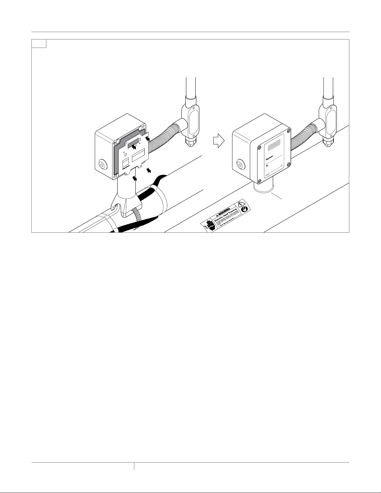
JBS-100-ECP-A with
Pyrotenax MI heating cable
using required MI cable
grounding kit
JBS-100-ECP-A with
Raychem heating cable
Actual
Setpoint
Temperature
JBS-100-ECP-A
Powerconnectionboxand digital electroniccontroller
Type4X
Input: 100-277Vac,50/60 Hz, 30 A
Output: 100-277Vac,30 A
MaximumAmbient: 140˚F(60˚C)
Formaintainingtemperatures up to 425 ˚F (220˚C)
innonhazardouslocations.
Usesupplywires suitable for at least 221˚F (105˚C).
Useonlywith certified Raychem BTV, QTVR, XL-Trace, XTV and VPL
heatingcablesand Raychem type A & D MI heating cables in
nonhazardouslocation.
©2004-2014PentairThermal Management LLC
WWW.PENTAIRTHERMAL.COM
PNP000000173 H57496 05/14
Actual
Setpoint
Temperature
JBS-100-ECP-A
Powerconnectionboxand digital electroniccontroller
Type4X
Input: 100-277Vac,50/60 Hz, 30 A
Output: 100-277Vac,30 A
MaximumAmbient: 140˚F(60˚C)
Formaintainingtemperatures up to 425˚F (220˚C)
innonhazardouslocations.
Usesupplywires suitable for at least 221˚F (105˚C).
Useonlywith certified Raychem BTV, QTVR, XL-Trace, XTV and VPL
heatingcablesand Raychem type A & D MI heating cables in
nonhazardouslocation.
©2004-2014PentairThermal Management LLC
WWW.PENTAIRTHERMAL.COM
PNP000000173 H57496 05/14
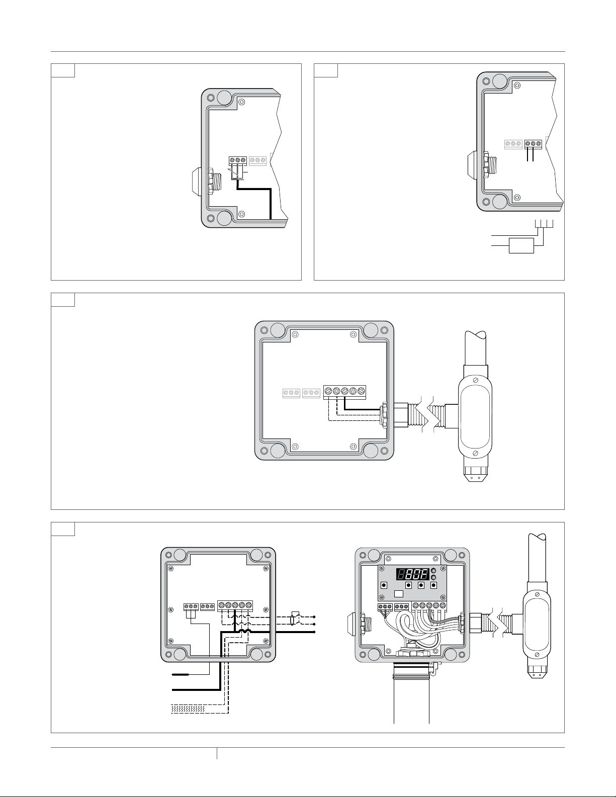
DESCRIPTION
The Raychem JBS-100-ECP-A is an electric heat-tracing power
connection / electronic controller combination housed in a NEMA 4X
rated enclosure. It is designed for use only with Raychem BTV-CR,
XL-Trace, BTV-CT, QTVR-CT, XTV-CT, VPL-CT, KTV-CT, and Pyrotenax
MI heating cables in nonhazardous locations.
These kits may be installed at temperatures as low as −40°F (−40°C).
For easier installation store above freezing until just before installation.
The controller can be programmed to maintain temperatures of 425°F
(220°C). It operates at voltages from 100 to 277 Vac and can switch
current up to 30 Amps.
For technical support call Pentair Industrial Heat Tracing Solutions at
(800)545-6258.
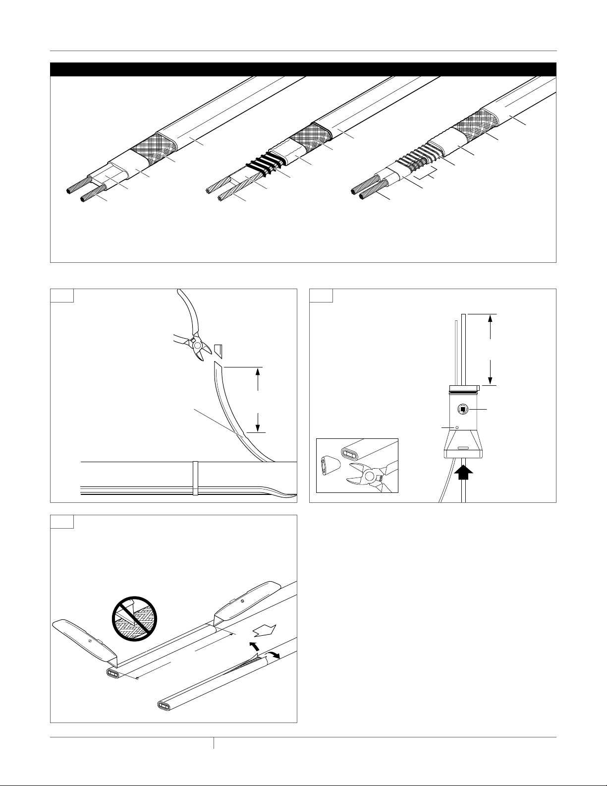
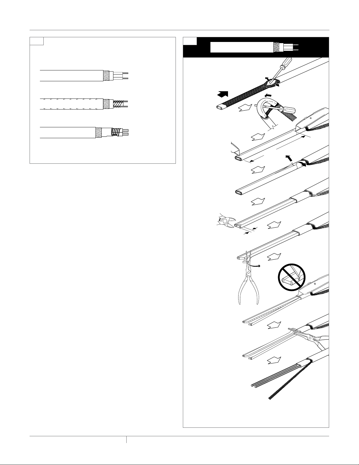
TOOLS REQUIRED
• Wirecutters • Pliersoradjustablewrench
• Utilityknife • Largeslottedscrewdriver
• Needlenosepliers • Smallslottedscrewdriver
• Wirestripper(forVPL-CT)
ADDITIONAL MATERIALS REQUIRED
• Pipestrap
• GT-66orGS-54fiberglasstape
• MIcablegroundingkit(forMIcableinstallations)
CatalogNo:MI-GROUND-KIT
• AT-180aluminumtape
• Smallpipeadapter(for1in(25mm)andsmallerpipes)
Catalog No: JBS-SPA
This component is an electrical device that must be installed
correctly to ensure proper operation and to prevent shock or fire.
Read these important warnings and carefully follow all of the
installation instructions.
• Tominimizethedangeroffirefromsustainedelectricalarcing
if the heating cable is damaged or improperly installed, and to
comply with the requirements of Pentair Industrial Heat Tracing
Solutions, agency certifications, and the National Electrical
Code, ground-fault equipment protection must be used. Arcing
may not be stopped by conventional circuit breakers.
• Componentapprovalsandperformancearebasedontheuseof
Pentair Industrial Heat Tracing Solutions-specified parts only.
Do not use substitute parts or vinyl electrical tape.
• Theblackheatingcablecoreandfibersareconductiveandcan
short. They must be properly insulated and kept dry.
• Damagedbuswirescanoverheatorshort.Donotbreakbuswire
strands when scoring the jacket or core.
• Keepcomponentsandheatingcableendsdrybeforeandduring
installation.
• Useonlyfireresistantinsulationmaterials,suchasfiberglass
wrap or flame-retardant foam.
HealtH Hazard: Prolonged or repeated contact with the
sealant in the core sealer may cause skin irritation. Wash hands
thoroughly. Overheating or burning the sealant will produce
fumes that may cause polymer fume fever. Avoid contamination
of cigarettes or tobacco. Consult MSDS VEN 0058 for further
information.
CHEMTREC 24-hour emergency telephone:
(800) 424-9300
Non-emergency health and safety information:
(800) 545-6258.
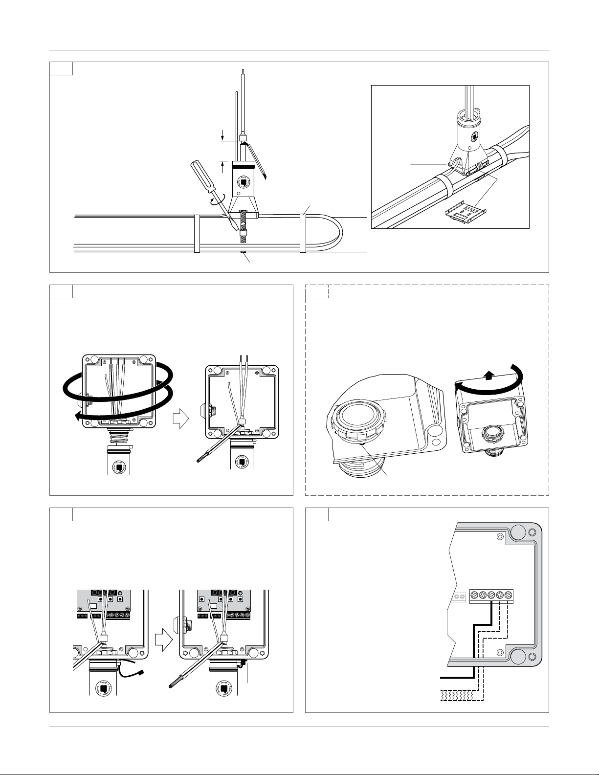
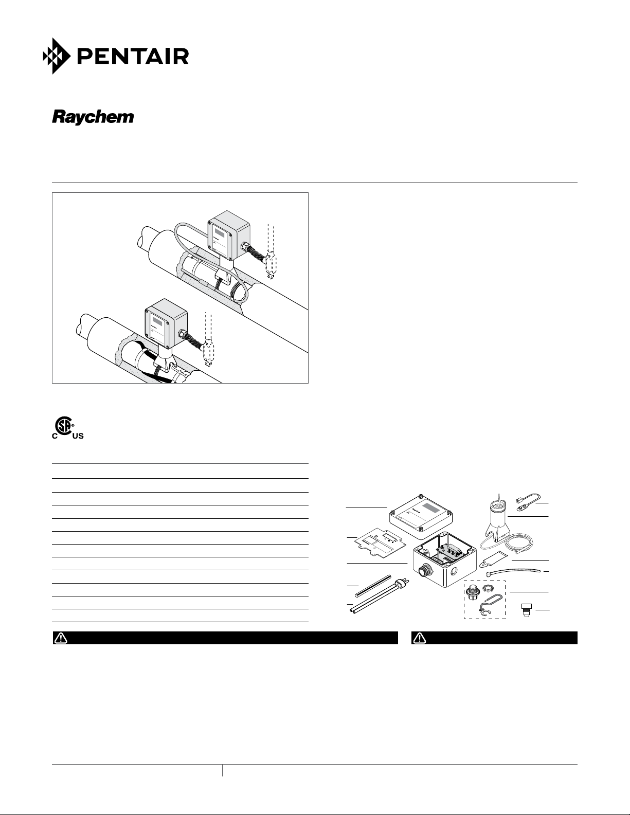
KIT CONTENTS
Item Qty Description
A 1 Lid
B 1 Wirecover
C 1 Box with electronics
D 1 Green/yellowtube
E 1 Core sealer (for use with Raychem heating cables only)
F 1 Battery connector
G 1 StandwithRTD
H 1 Cable lubricant (for use with Raychem heating cables only)
I 1 Cable tie
J 1 MI cable grounding kit (ordered separately; P000000279)
K 1 Plug (for use with MI cable installations only)
APPROVALS
Nonhazardous locations
A
G
F
H
I
B
C
D
EK
J
Actual
Setpoint
Temperature
JBS-100-ECP-A
Powerconnectionbox and digitalelectroniccontroller
Type4X
Input: 100-277Vac, 50/60 Hz, 30 A
Output: 100-277Vac, 30 A
MaximumAmbient: 140˚F (60˚C)
Formaintaining temperatures up to 425˚F (220˚C)
innonhazardous locations.
Usesupply wires suitable for at least 221˚F (105˚C).
Useonly with certified Raychem BTV, QTVR, XL-Trace,XTV and VPL
heatingcables and Raychem type A & D MI heating cables in
nonhazardouslocation.
©2004-2014Pentair Thermal Management LLC
WWW.PENTAIRTHERMAL.COM
PNP000000173 H57496 05/14
Hold 3 Seconds
WARNING
Shock Hazard
ALARMS / ERRORS:
rtd Err = Shorted or Open Sensor
Hi Alr = High Alarm
Lo Alr = Low Alarm
Do not remove cover while energized
Ne pas enlever le couvert tant que le
régulateur est sous tension
TEMPERATURE
Next
MENU
Battery
Connection
Up Down
ACTUAL
SETPOINT
SETTINGS:
1 - *F or *C
2 - Set Point
3 - Dead Band
4 - High Alarm
5 - Low Alarm
JBS-100-EC-A
Digital Thermostat