Pentair Raychem EMK-XP User manual

1 / 10
EMK-XP
ElEctroMElt PowEr connEction and End SEal Kit inStallation inStructionS
DESCRIPTION
The ElectroMelt EMK-XP Power Connection and End Seal Kit is for
use with ElectroMelt EM2-XR heating cable for snow-melting and
anti-icing applications. Materials for one power connection and
one end seal are included. This kit is suitable for connecting the
heating cable to 14 through 4 AWG (Cu only) power wires. Power
wiring must meet NEC or CEC requirements and have a minimum
temperature rating of 167°F (75°C).
These installation instructions should be used in conjunction with
the ElectroMelt System Design Guide (H53393) and ElectroMelt
System Installation and Operation Manual (H58086).
For technical support call Pentair Thermal Management at
(800)545-6258.
TOOLS REQUIRED
• Needle-nose pliers • Utility knife
• Heat gun or propane torch • Wire strippers
• Ideal Crimp Tool Model 30-425 • Diagonal cutters
ADDITIONAL MATERIALS REQUIRED
• EMK-XJB (Not shown) or equivalent UL Listed or CSA Certified
weatherproof junction box suitable for the location. A minimum
of 400 cubic inches are needed for 1 power connection and 1 end
termination per junction box.
This component is an electrical device that must be installed correctly to ensure proper
operation and to prevent shock or fire. Read these important warnings and carefully follow
all the installation instructions.
• To minimize the danger of fire from sustained electrical arcing if the heating cable
is damaged or improperly installed, and to comply with the requirements of Pentair
Thermal Management, agency certifications, and national electrical codes, ground-
fault equipment protection must be used. Arcing may not be stopped by conventional
circuit breakers.
• Approvals and performance are based on the use of Pentair Thermal Management-
specified parts only. Do not substitute parts or use vinyl electrical tape.
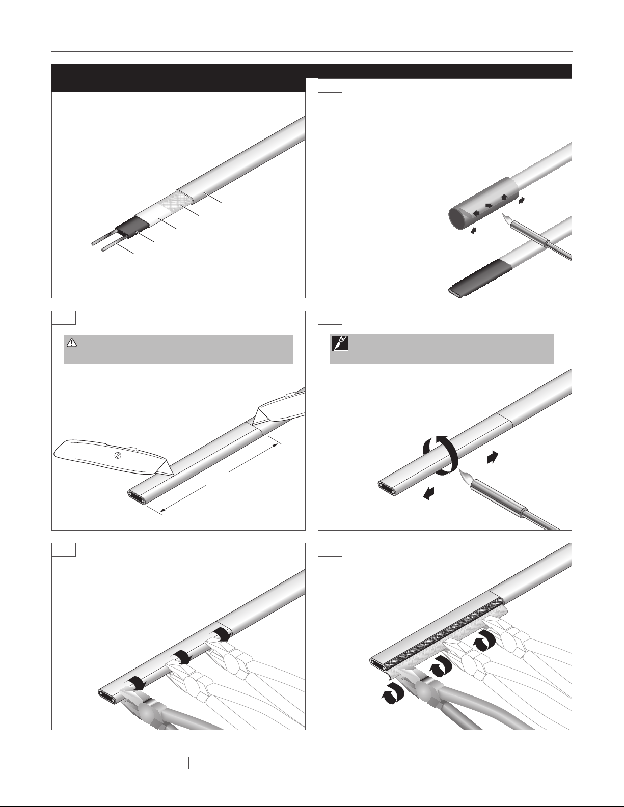
• The black heating cable core is conductive and can short. It must be properly insulated
and kept dry.
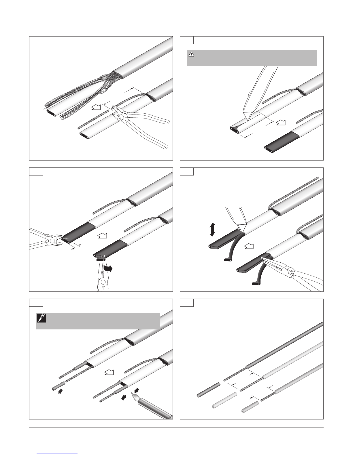
• Damaged bus wires can overheat or short. Do not break bus wire strands when scoring
the jacket or core.
• Do not bury any of the components. Both the power connection and end seal must be
installed in a dry junction box.
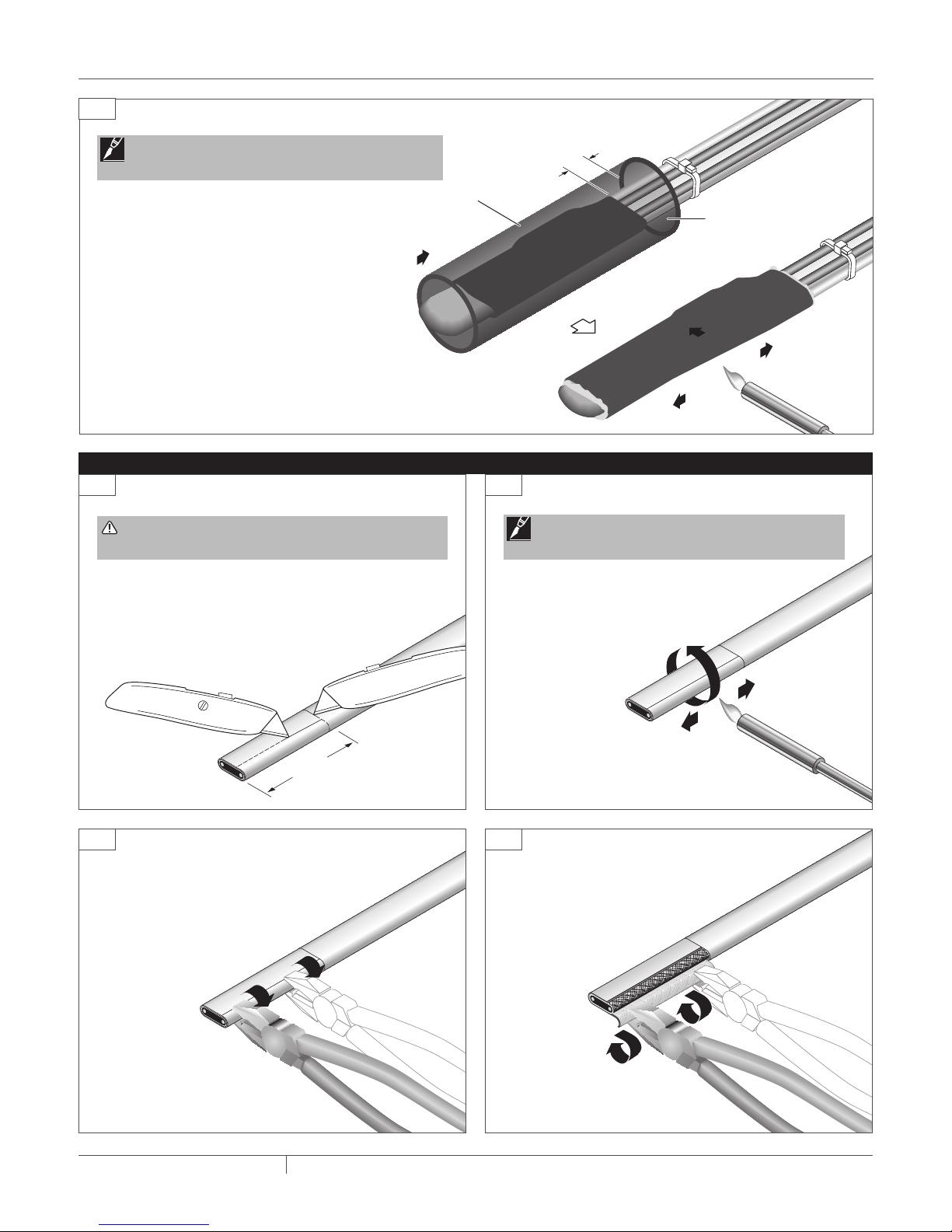
• Heat-damaged components can short. Use a heat gun or torch with a soft, yellow, low-
heat flame. Keep the flame moving to avoid overheating, blistering, or charring the
heat-shrinkable tubes. Avoid heating other components. Replace any damaged part.
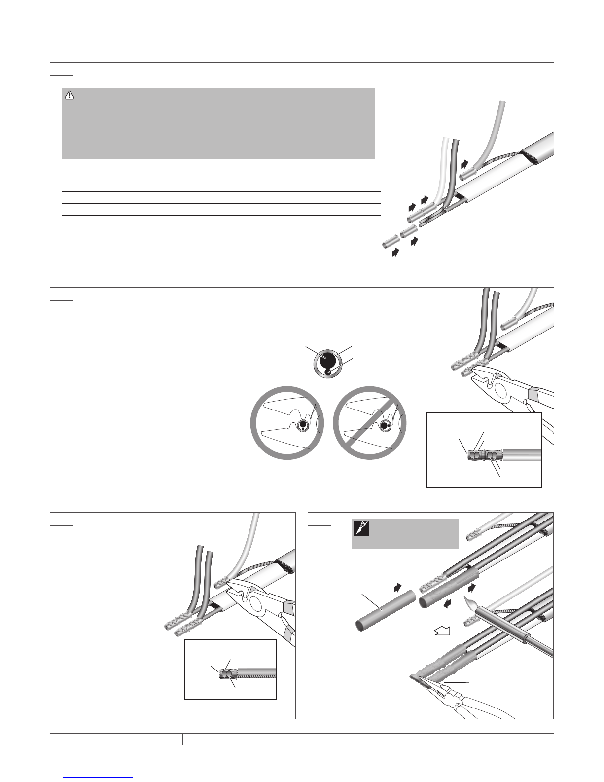
• Bus wires will short if they contact each other. Keep bus wires separated.
• Connection kits and heating cable ends must be kept dry before and during
installation.
• Damaged heating cable can cause electrical arcing or fire. Use only plastic cable ties
to secure the heating cable to the reinforcement. Do not use metal attachments such
as tie wire.
• Do not attempt to repair or energize damaged heating cable. Remove damaged
sections at once and replace them with a new length using the appropriate Raychem
splice kit. Replace damaged connection kits.
• Megohmmeters operate at high voltage. This voltage is hazardous and possibly lethal.
Read and follow all instructions included with the instrument you are using.
HealtH Hazard: Over heating heat-shrinkable tubes will produce
fumes that may cause irritation. Use adequate ventilation and avoid
charring or burning. Consult MSDS RAY4566 for further information.
CHEMTREC 24-hour emergency telephone:
(800) 424-9300
Non-emergency health and safety information:
(800) 545-6258.
WARNING:
CAUTION:
KIT CONTENTS
Item Qty Description
Power Connection
A 1 Black heat-shrinkable tube – 1 1/2 x 6 in (38 x 152 mm)
B 1 Heat-shrinkable cap
C 2 Clear yellow heat-shrinkable tubes – 1/2 x 2 3/4 in (13 x 70 mm)
D 1 Clear yellow heat-shrinkable tube – 1/2 x 2 in (13 x 51 mm)
E 2 “Electric Deicing and Snow Melting” labels
F 2 Black heat-shrinkable tubes – 1/8 x 3/4 in (3 x 19 mm)
G 5 Small non-insulated crimp connectors
H 5 Large non-insulated crimp connectors
I 1 Cable tie
J 1 Mastic sheet – 3 x 12 in (76 x 305 mm)
End Seal
A 1 Black heat-shrinkable tube – 1 1/2 in x 6 in (38 mm x 152 mm)
J 1 Mastic sheet – 3 in x 12 in (76 mm x 305 mm)
K 1 Black heat-shrinkable tube – 1 in x 3 in (25 mm x 76 mm)
L 1 Clear yellow heat-shrinkable tube – 1/2 in x 1 1/2 in (13 mm x 38 mm)
APPROVALS
LISTED
877Z
DE-ICING AND
SNOW MELTING EQUIPMENT
-W
A
B
C
D
E
F
G
H
I
J
K
L
THERMAL BUILDING SOLUTIONS Raychem-IM-H57284-EMKXP-EN-1612

THERMAL BUILDING SOLUTIONS Raychem-IM-H57284-EMKXP-EN-1612 2 / 10
Core (black)
Bus wire
Inner jacket (white)
Braid
Outer jacket (orange)
EM2-XR Heating Cable
4 in
(102 mm)
2
4 5
1
3
• Allow 12 in (305 mm) of heating cable
in junction box for proper assembly.
• Score around outer jacket 4 in (102
mm) from end. Make one lengthwise
score as shown.
• Use Ideal crimp tool No. 30-425 or blunt nose pliers to
pull outer jacket from braid.
• Gently heat end of cable to loosen bond
between outer jacket and braid.
• Roll outer jacket back around
heating cable to remove.
Note: See Step 1 for proper heating techniques.
Instructions for using a heat gun or torch:
• Read important warnings on page 1 and follow
safety precautions provided with heat gun or torch.
• When using a torch use a soft yellow, low-heat
flame. Apply just enough heat to do the job.
• Keep torch or heat gun moving
continuously to distribute the heat
evenly to avoid overheating,
blistering or charring the
heating cable and heat-
shrinkable tubes.
• Replace any heat-
damaged parts.
Power Connection Installation and Assembly for ElectroMelt Snow-melting and Anti-icing System
HEATING CABLE CONSTRUCTION
WARNING: Do not cut into braid or inner jacket. This
could result in a short circuit.

3 / 10
THERMAL BUILDING SOLUTIONS Raychem-IM-H57284-EMKXP-EN-1612
2 in
(51 mm)
¼ in
(6 mm)
1½ in
(38 mm)
Power supply
Equipment ground
1 in
(25 mm)
6
8
10 11
2¼ in
(57 mm)
7
9
• Unravel braid and twist into a pigtail.
• Trim braid.
• Notch core at the end.
• Twist back and peel bus
wire from core.
• Slide 3/4 in (19 mm)
long tubes (Item F)
over bus wires.
• Shrink tubes
completely.
• Lightly score inner
jacket around and
down as shown.
• Bend heating cable
to break jacket at
score.
• Peel off jacket.
• Score between bus wires at inner jacket.
• Bend core to break free at inner jacket.
• Peel core and any remaining material
from bus wires.
• Remove 1 1/2 in (38 mm) insulation
from power supply lines.
• Remove 1 in (25 mm) insulation from
equipment grounding conductor.
Note: See Step 1 for proper heating techniques.
WARNING: Do not cut or damage bus wires.
Damaged wires can overheat or short.

THERMAL BUILDING SOLUTIONS Raychem-IM-H57284-EMKXP-EN-1612 4 / 10
Power
supply
wires
Bus wires
Braid
Equipment
grounding
conductor
Crimp
IncorrectCorrect
Conductor position in crimp
Supply
wire Heating
cable
bus wire
Detail
2121
2nd crimp
2nd crimp
1st crimp
Trim
excess
wire
1st crimp
21
1st crimp
2nd crimp
Trim
excess
wire
Detail
2 ¾ in (70 mm)
clear yellow
shrink tube
Hold for 5 seconds
12
13
14 15
• Select the correct crimp connectors for the gauge of power supply wire used (see table).
Supply wire gauge Crimp connector size
8 – 14 AWG Ideal 411 (small, Item G)
4 – 6 AWG Ideal 412 (large, Item H)
• Connect power supply wires to bus wires. Use two crimps for each connection and
crimp twice on each connector (see Step 13).
• Use one crimp connector to attach equipment grounding conductor to heating cable
braid (see Step 14).
• Use the correct crimp tool (Ideal 30-425) when
making the connections.
• To make the proper crimp connection, position the
heating cable bus wire directly below the larger
supply wire.
• Position the supply wire and bus wire in the crimp
connectors and crimp tool exactly as shown.
• Crimp each connector twice (see detail).
• Use only one crimp
connector to attach
equipment grounding
conductor to heating cable
braid (see detail).
• Slide 2 3/4 in (70 mm) long clear
yellow tubes (Item C) over bus
wire connectors.
• Shrink one tube completely and
immediately pinch end while
tube is hot; hold for
5 seconds to ensure
seal.
• Repeat for second tube.
• Allow tubes to cool.
WARNING: Shock and Fire Hazard
Improper crimp connections can cause overheating and a danger of shock and
fire. Carefully follow the crimping instructions in Step 13 to ensure a proper
electrical connection.
Do not substitute crimps or wire nuts. Component approvals and performance
are based on Pentair Thermal Management-specified parts only.
Note: See Step 1 for
proper heating techniques.

5 / 10
THERMAL BUILDING SOLUTIONS Raychem-IM-H57284-EMKXP-EN-1612
2 in (51 mm)
clear yellow
shrink tube
1½ in
(38 mm)
Hold for 5 seconds
3 in
(76 mm) 1 ¾ in
(44 mm)
3 in
(76 mm)
5 in
(127 mm)
5 in
(127 mm)
16
17
19 20
1¾ in
(44 mm)
18
• Slide 2 in (51 mm) long clear yellow
tube (Item D) over braid wire/ground
connector.
• Shrink tubes completely and
immediately pinch end while tube is
still hot; hold for 5 seconds to ensure
seal.
• Allow tubes to cool.
• Cut two 3 in x 1 3/4 in (76 mm x 44 mm)
pieces from one mastic sheet (Item J).
• Cut a 3 in x 5 in (76 mm x 127 mm)
piece from one mastic sheet (Item J).
• Wrap each power
wire with a 3 in x 1 3/4
in (76 mm x 44 mm)
piece of mastic.
• Fold the
covered
power wires
flat against
the heating
cable.
• Use the 3 in x 5 in (76 mm x 127 mm) mastic sheet
to cover the first mastic sheet, bus wires, and wire
connectors. Do not cover outer jacket with mastic.

THERMAL BUILDING SOLUTIONS Raychem-IM-H57284-EMKXP-EN-1612 6 / 10
3 in
(76 mm)
6 in
(152 mm)
½ in
(13 mm)
2 in
(51 mm)
3 in
(76 mm)
Cable tie
Pinch and
squeeze mastic
Trim
Braid
connection
21
22
23
• Position the heat-shrinkable cap (Item B)
over the second mastic sheet. Push it all the
way down.
• Heat the cap until it shrinks completely.
• Cut second mastic sheet (Item J) into two pieces. 3 in x 6
in (76 mm x 152 mm)
• Secure all wires 2 in (51 mm) from end
of outer jacket using cable tie (Item I).
• Position braid connection next to cap.
• Wrap braid connection and 1/2 in (13
mm) of outer jacket with 3 in x 6 in (76
mm x 152 mm) mastic sheet (Item J).
Note: See Step 1 for proper heating techniques.
IMPORTANT: If cap starts to slide off end while shrinking,
pull it back in place and hold until it cools.

2 in
(51 mm)
1
3 4
2
• Allow 12 in (305 mm) of heating cable in junction box for
proper assembly.
• Score around outer jacket 2 in (51 mm) from end.
• Make one lengthwise score as shown.
• Use Ideal crimp tool No. 30-425 or blunt
nose pliers to pull outer jacket from braid.
• Gently heat cable to loosen bond
between outer jacket and braid.
• Roll outer jacket back around
heating cable to remove.
7 / 10
THERMAL BUILDING SOLUTIONS Raychem-IM-H57284-EMKXP-EN-1612
½ in
(13 mm)
6 in (152 mm) tube
Heat this end first
24
• Position the 6 in (152 mm) long heat-
shrinkable tube (Item A) over the mastic sheet,
1/2 in (13 mm) from end of mastic sheet.
• Begin heating tube at end near cable tie.
• Heat until tube is recovered completely and
adhesive or mastic flows from ends.
• Continue to heat center section to melt mastic
inside but do not blister or burn tube.
• Allow the connection to cool before placing in
junction box.
Note: See Step 1 for proper heating techniques.
End Seal Installation Instructions
WARNING: Do not cut into braid or inner jacket. This
could result in a short circuit.

THERMAL BUILDING SOLUTIONS Raychem-IM-H57284-EMKXP-EN-1612 8 / 10
Smooth down any
sharp ends
3 in
(76 mm)
1½ in
(38 mm)
6 in
(152 mm)
¼ in
(6 mm)
Adhesive or
Mastic
Outer tube extends
past inner mastic
Adhesive
Hold for
20 seconds
5
7
9
½ in
(13 mm)
Short tube
Hold for 5 seconds
¼ in
(6 mm)
1 ½ in
(38 mm)
6
8
• Trim braid flush with outer jacket.
• Cut a 3 in x 1 1/2 in (76 mm x 38 mm)
piece from mastic sheet (Item J).
• Position 3 in (76 mm) long heat-shrinkable
tube (Item K) over the mastic and position
1/4 in (6 mm) from outer jacket.
• Heat the tube until adhesive or mastic flows
out ends.
• Remove heat source and immediately pinch
end with needle-nose pliers for 20 seconds
to ensure a complete moisture seal.
• Allow tube to cool completely.
• Refer to Material Safety Data Sheet RAY4566.
• Position short tube (Item L) over end of heating cable as
shown.
• Heat tube until it shrinks and adhesive flows out ends.
• While still hot, gently pinch end and hold for 5 seconds to
ensure a complete moisture seal.
• Allow tube to cool completely.
• Wrap 3 in x 1 1/2 in (76 mm x 38 mm) mastic around
heating cable 1/4 in (6 mm) from outer jacket.
Note: See Step 1 for proper heating techniques.
Note: Heat-shrinkable tubing must be installed to prevent
electrical short. See Step 1 for proper heating techniques.

9 / 10
THERMAL BUILDING SOLUTIONS Raychem-IM-H57284-EMKXP-EN-1612
1 in
(25 mm)
3 in
(76 mm)
½ in
(13 mm)
Heat this
end first
Adhesive
Adhesive
Hold for
20 seconds
10
11
12
• Wrap remaining 3 x 4 1/2 in (76 mm x 114 mm) mastic
sheet (Item J) around outer jacket with 1 in (25 mm)
overlapping the recovered heat-shrinkable tubing.
• Slide the 6 in (152 mm) long heat-shrinkable tube
(Item A) over end. Position tubing so 1/2 in (13 mm)
extends beyond pinched end of inner tube.
• Begin heating tube at end next to mastic sheet.
• Heat the tube until it is completely recovered and
adhesive or mastic flows out ends.
• Continue to heat center section to melt mastic
inside but do not blister or burn tube.
• Remove heat source and immediately pinch end
with needle-nose pliers for 20 seconds to ensure a
complete moisture seal.
• Allow end seal to cool completely. Position end seal so it
does not come in contact with power connection.
• Route heating cable so that power connection and end
seal are in same junction box. Use an EMK-XJB junction
box or agency certified equivalent. A minimum of 400
cubic inches are needed for 1 power connection and 1 end
termination per junction box.
• Apply "Electrical Deicing and Snow Melting" label (Item E)
on junction box cover. Place second label near installation
where applicable.
• Leave these installation instructions with the end user for
future reference.
Note: See Step 1 for proper heating techniques.

10 / 10THERMAL buiLding SOLuTiOnS Raychem-IM-H57284-EMKXP-EN-1612
WWW.PENTAIRTHERMAL.COM
© 2008-2016 Pentair. PN 385755-000
NORTH AMERICA
Tel: +1.800.545.6258
Fax: +1.800.527.5703
Tel: +1.650.216.1526
Fax: +1.650.474.7711
thermal.info@pentair.com
Pentair and ElecroMelt are owned by Pentair or its global affiliates. All other trademarks are the property of their respective owners. Pentair reserves the
right to change specifications without prior notice.
Table of contents
Other Pentair Cables And Connectors manuals

Pentair
Pentair Raychem T-100 User manual

Pentair
Pentair DigiTrace E104 User manual

Pentair
Pentair Raychem CCON25-100 User manual

Pentair
Pentair Raychem C25-21 User manual

Pentair
Pentair Raychem FrostGuard User manual

Pentair
Pentair Raychem C25-100-FHP User manual

Pentair
Pentair Raychem E-100-A User manual

Pentair
Pentair Raychem FrostGuard 240 V User manual

Pentair
Pentair Raychem H900 User manual

Pentair
Pentair CodeLine 40E60 User manual