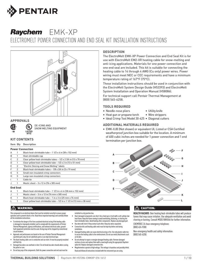
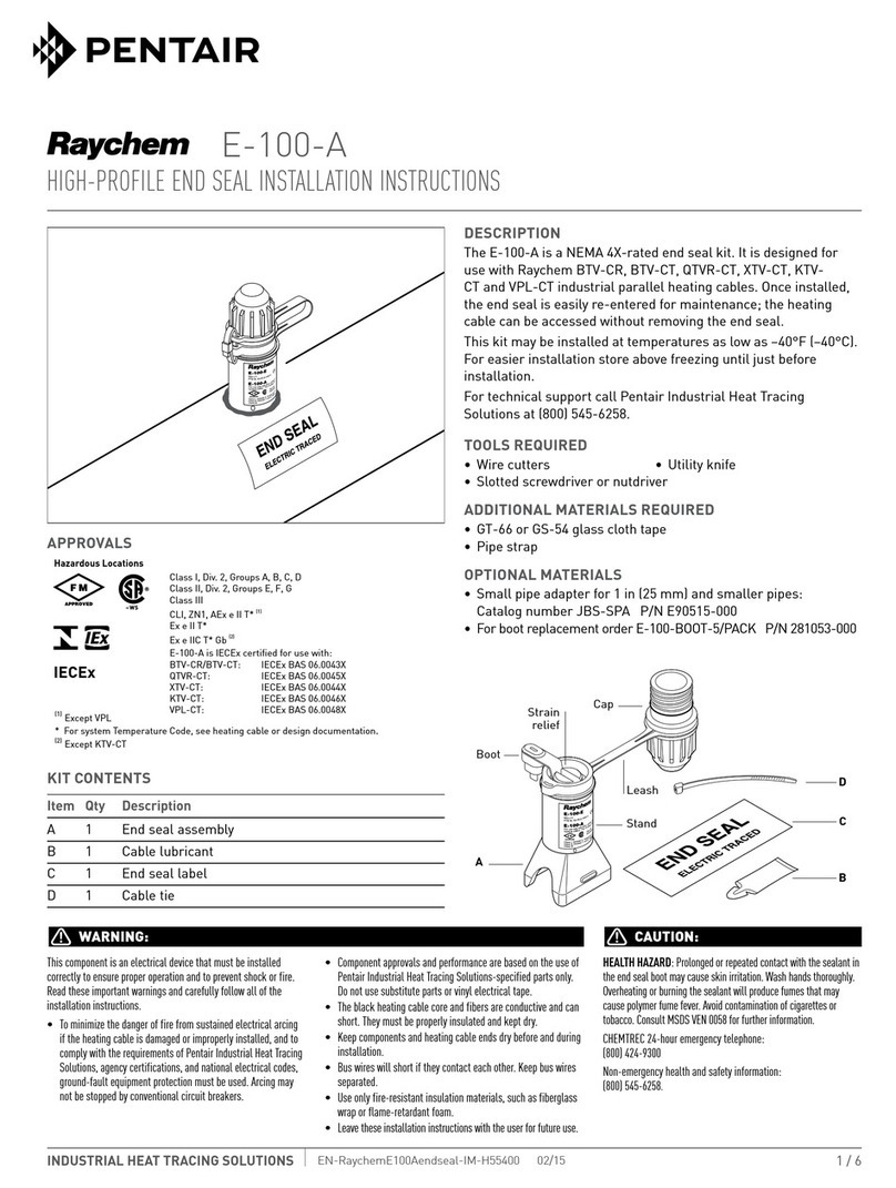
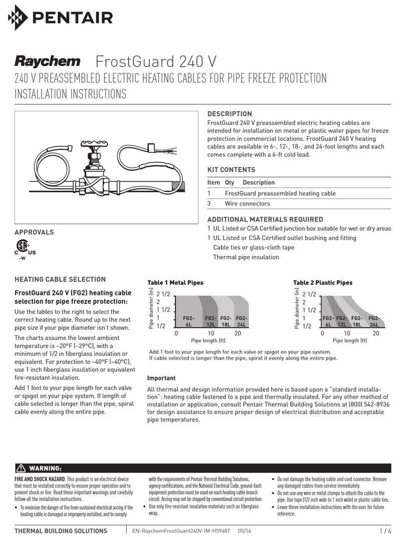
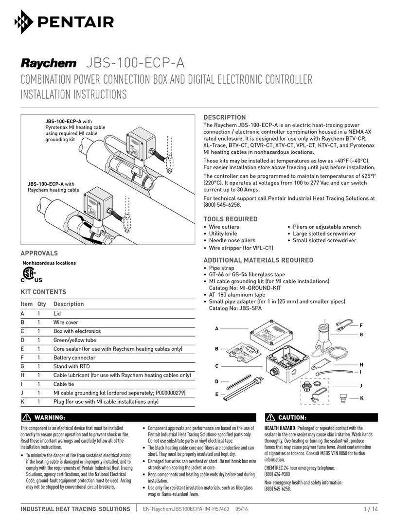
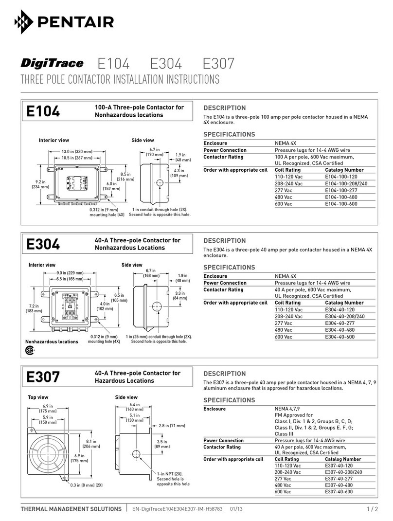
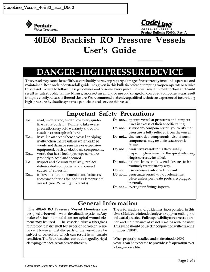
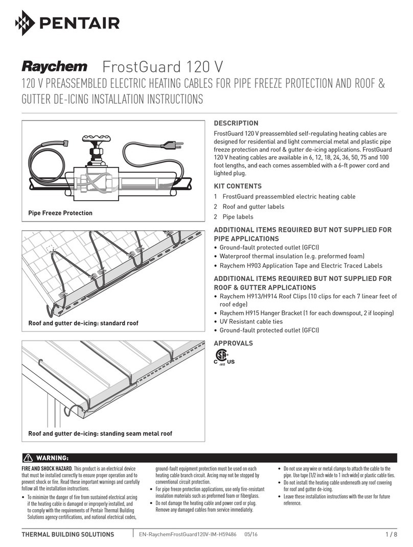
Pentair Raychem H900 User manual

1 / 12
H900
WinterGard PoWer ConneCtion Kit With end Seal inStallation inStruCtionS
THERMAL MANAGEMENT SOLUTIONS EN-RaychemWinterGardH900-IM-H5366501/13
Power connection for
H311, H611, and H621 Power connection for
H612 and H622
DESCRIPTION
The WinterGard power connection kit is for use only with the following
WinterGard heating cables: H311, H611, H612, H621, and H622.
Materials for one power connection and one end seal are included.
All WinterGard heating cables are designed for water-pipe freeze
protection applications. Only the H612 and H622 cables can be used for
both pipe freeze protection and roof and gutter de-icing applications.
Do not use this kit with aluminum feed wires. For additional technical
support call Pentair Thermal Management at (800)545-6258.
Note: For WinterGard heating cables in pipe heating applications, refer
to pages 3–5. For WinterGard Wet heating cables H612 and H622 in
roof and gutter de-icing applications, refer to pages 6–8.
TOOLS REQUIRED
• Needlenosepliers • Pen
• Propanetorchorheatgun • Diagonalcutters
• Utilityknife • PanduitCT100crimptool
• Adjustablewrench • Screwdriver
ADDITIONAL MATERIALS REQUIRED
• ULListedorCSACertifiedjunctionboxsuitableforthelocation,with
aclearanceholefor1/2-inchconduitor1/2-inchNPTthreadedhub.
• ForH311,H611,andH621,youmustuseametallicjunctionboxto
ensure proper grounding.
• YourapplicationmayrequireadditionalWinterGardaccessories;
forexample,H903applicationtapeforpipeapplications;H913/
H914roofclipsand/orH915downspouthangersforroofandgutter
de-icing applications.
These components are electrical devices. They must be installed correctly to
ensure proper operation and to prevent shock or fire. Carefully follow all of
the installation instructions and read these important warnings.
• Tominimizethedangeroffirefromsustainedelectricalarcingifthe
heating cable is damaged or improperly installed, and to comply with the
requirements of Pentair Thermal Management and national electrical codes,
ground-fault equipment protection must be used on each heating cable
branch circuit. Arcing may not be stopped by conventional circuit protection.
• Componentapprovalsandperformancearebasedontheuseofspecified
parts only. Do not substitute parts or use vinyl electrical tape.
• Theblackheating-cablecoreisconductiveandcanshort.Itmustbe
properly insulated and kept dry.
• Keepcomponentsandheatingcableendsdrybeforeandduring
installation.
• Damagedbuswirescanoverheatorshort.Donotbreakbraidorbuswire
strands when scoring the jacket or core.
• Buswireswillshortiftheycontacteachother.Keepbuswiresseparated.
• Heat-damagedcomponentscanshort.Useaheatgunoratorchwitha
soft,yellow,low-heatflame,notabluefocusedflame.Keeptheflame
moving to avoid overheating, blistering, or charring the heat-shrinkable
tubes. Avoid heating other components. Replace any damaged parts.
• Useonlyfire-resistantinsulationmaterialssuchasfiberglasswrap.
• Leavetheseinstallationinstructionswiththeuserforfuturereference.
Charring or burning the heat-shrinkable tubes in this kit will produce fumes
that may cause eye, skin, nose, and throat irritation. Consult Material Safety
Data Sheet RAY3122.
CHEMTREC24-houremergencytelephone:
(800)424-9300
Non-emergencyhealthandsafetyinformation:
(800)545-6258.
WARNING:
CAUTION:
APPROVALS
718K Pipe Heating Cable,
Also Listed as De-Icing and
Snow Melting Equipment -ws
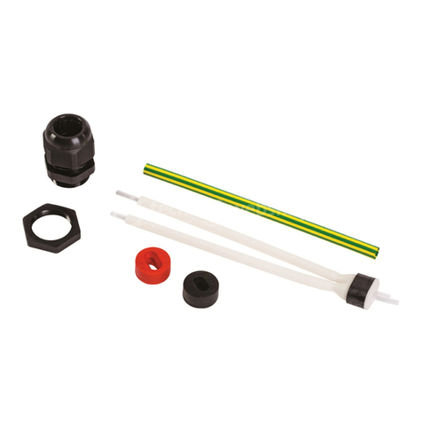
KIT CONTENTS
Item Qty Description
A 4 Labels
B 1 Pipe mounting bracket
C 1 Locknut
D 1 Blue grommet
E 1 Sealingfittingwithblackgrommet
F 3 Wire nuts
G 1 Blackheat-shrinkabletube(1/2"x1")
H 1 Green/yellowheat-shrinkabletube(1/4"x6")
I 2 Blackheat-shrinkabletubes(1/8"x51/2")
J 1 Green grounding screw and kep nut
K 1 Gel-filled end seal
L 1 Ringterminal
M 1 Black cloth tape (6" long)
N 1 Sealinggasket
B
A
D
F
C
E
H
G
I
J
K
L
M
N
WARNING
Fire and Shock Hazard
Self-regulating electrical
heating cable attached to this pipe:
Disconnect before sevicing
Electric Deicing and
Snow Melting Equipment
on Premises
WARNING
Fire and Shock Hazard
Self-regulating electrical
heating cable attached to this pipe:
Disconnect before sevicing
Electric Deicing and
Snow Melting Equipment
on Premises

THERMAL MANAGEMENT SOLUTIONS EN-RaychemWinterGardH900-IM-H5366501/13 2 / 12
Important: For the Pentair Thermal Management warranty to be
valid,youmustcomplywithalltherequirementsoutlinedinthese
guidelines.
Allthermalanddesigninformationprovidedhereisbasedupona
“standard” installation with heating cable fastened to an insulated
pipe. For any other application or method of installation, consult
Pentair Thermal Management at (800) 545-6258.
HEATING CABLE SELECTION AND DESIGN
Make sure that the heating cable being used is suitable for your
application.RefertotheCommercialandResidentialApplicationand
Design Guide (H53585) for heating cable application information.
1. Determine the heating cable type.
UseTable1toselectheatingcablesforinsulatedmetalpipes.Use
Table2toselectheatingcablesforinsulatedplasticpipes.Read
across the table to find your pipe size, then drop down to the line
corresponding to the lowest air temperature for that application and
the correct insulation thickness. The cell at that intersection has a
particularshadingandmayhaveanumber.Theshadingindicates
whichheatingcabletouse(keytotheshadingappearsabovethetable
headings). A number represents the spiraling ratio (feet of heating
cable per foot of pipe).
If no number appears in the cell, straight trace the pipe. If a number
does appear in the cell, spiral trace the pipe.
If your spiraling ratio is 2.0, multiple trace the pipe using two straight
traces at the 4 o’clock and 8 o’clock positions.
If your spiraling ratio is 3.0, multiple trace the pipe using three
straight traces at the 11 o’clock or 1 o’clock position, and at the 4
o’clock and 8 o’clock positions.
Example 1:
Pipe size: 1 in
Lowestairtemp.: 0°F
Insulation thickness: 1/2 in
Metal pipe:
WinterGard H311
Plastic pipe:
WinterGard Plus H611, H621
WinterGard Wet H612, H622
Example 2:
Pipe size: 2 1/2 in
Lowestairtemp.: –20°F
Insulation thickness: 1/2 in
Metal pipe: 1.3 WinterGard Plus H611, H621
WinterGard Wet H612, H622
(Use1.3feetofheatingcable
per foot of pipe.)
Plastic pipe: 2.0 WinterGard Plus H611, H621
WinterGard Wet H612, H622
(Usetwostraighttracesatthe4o’clockand8o’clockpositions.)
Table 1. For METAL pipes with fiberglass insulation or equivalent (based on 40°F maintain temperature)
Table 2. For PLASTIC pipes with fiberglass insulation or equivalent (based on 40°F maintain temperature)
Lowest air
temp. (°F)
Insulation
thickness
Nominal pipe size
1/2 in 6 in4 in3 in2 1/2 in2 in1 1/2 in1 1/4 in1 in3/4 in
1/2 in
1 in
1 1/2 in
1/2 in
1 in
1 1/2 in
2 in
1/2 in
1 in
1 1/2 in
2 in
0
–20
–40
1.81.3
3.01.81.51.31.1
1.51.1
1.1
3.02.01.71.41.21.1
1.91.41.1
1.4
1.1
Key to Table 1: = H311 = H611, H612, H621, H622 = Use a thicker insulation
3.02.01.7
3.01.81.51.31.1
3.01.8
1.4
1.7
3.03.02.01.81.51.1
3.0
1.61.41.2
3.0
1.8
1.41.2
1.61.2
1.2
2.0
1.21.1
1.31.1
1.4
1.1
1.1 1.9
1.71.41.21.1
1.31.1
Lowest air
temp. (°F)
Insulation
thickness
Nominal pipe size
1/2 in 6 in4 in3 in2 1/2 in2 in1 1/2 in1 1/4 in1 in3/4 in
1/2 in
1 in
1 1/2 in
1/2 in
1 in
1 1/2 in
2 in
1/2 in
1 in
1 1/2 in
2 in
0
–20
–40
Key to Table 2: = H311 = H611, H612 H621, H622 = Use a thicker insulation
H900 DESIGN AND INSTALLATION INFORMATION FOR HEATING CABLE ON PIPES ONLY
WINTERGARD H311, H611, H621, H612, AND H622 HEATING CABLES.

3 / 12THERMAL MANAGEMENT SOLUTIONS EN-RaychemWinterGardH900-IM-H5366501/13
THERMAL MANAGEMENT SOLUTIONS 3 / 12
2. Calculate the total heating cable length required
Length =A+B+C+D+E+F+G+H
APipe lengthxspiralingratio
B 4ftx#gate/globevalvesxvalvelength(ft)xspiralingratio
C 2ftx#ball/butterflyvalvesxvalvelength(ft)xspiralingratio
D 2ftx#flangesxpipediameter(ft)xspiralingratio
E 2ftx#pipesupportsvpipediameter(ft)xspiralingratio
F1 ft for each power connection
G2 ft for each splice connection
H3 ft for each tee connection
= Total heating cable length (ft)
3. Determine the maximum heating cable circuit length allowed.
SeeTable3onthenextpage.Ensurethatyourcircuitsdonot
exceedthemaximumcircuitlengthlistedinTable3.Ifnecessary,
use additional shorter circuits.
Example (takenfromExample2[onmetalpipe],page3):
Pipe length: 50 ft
Spiralratio: 1.3(fromTable1,page3)
Globevalves: 3(each0.5ftlong)
Pipe supports: 10 supports for 1 in pipe
Power connections: 1
Spliceconnections: 1
WinterGard heating cable required:
A Pipelengthxspiralratio = 50 ftx1.3 = 65.0 ft
B 3globevalves(0.5fteach) = 4 ftx3 x0.5 x1.3 = 7.8 ft
C 0ball/butterflyvalves = 0 = 0
D0 flanges = 0 = 0
E10 pipe supports = 2 ft x10x0.085*x1.3 = 2.2 ft
F1 power connection = 1 ft x1 = 1.0 ft
G1 splice connection = 2 ft x1 = 2.0 ft
H0 tee connection = 0 = 0
Total heating cable length required = 78.0 ft
*1inpipediameter/12inperfoot=0.085foot
HEATING CABLE INSTALLATION
1. Prepare for installation.
•Storetheheatingcableinaclean,dryplace.
•Completepipingpressuretest.
•ReviewtheWinterGardheatingcabledesignandcompareto
materialsreceivedtoverifythattheproperWinterGardheating
cableandaccessoriesareavailable.TheWinterGardheating
cablewillhavetheheatingcabletypeprintedontheouterjacket.
•WalkthesystemandplantheroutingoftheWinterGard
heating cable on the pipe.
2. Cut the heating cable to length.
•Cuttheheatingcabletothelengthrequired.Thiscanbedone
beforeorafterthecableisattachedtothepipe.Leaveaminimum
of1footextraheatingcableforconnectiontopower.Forsplice
andteeconnections,leaveaminimumof1footforeachsection
of heating cable. WinterGard heating cable can be cut to length
without affecting its heat output per foot.
•Protecttheheatingcableendsfrommoistureormechanical
damageiftheywillbeleftexposedbeforeconnection.
3. Position and attach heating cable to pipe.
•Besureallpipingtobetracedisdry.
•Installheatingcable,usingstraighttracing,spiraling,ormultiple
tracing according to the “Heating cable selection and design”
section on page 3.
•Forstraighttracing,installtheheatingcableonalowerhalfofthe
pipe;forexample,inthe4o’clockor8o’clockposition.
•Besuretoinstalltheadditionalheatingcablerequiredforvalves,
flanges,etc.asindicatedinStep2ofthe“Heatingcableselection
and design” section.
•Whenthedesigncallsforspiraling,beginbysuspendingaloop
every10feetasshowninFigure1.Todeterminethelooplength,
obtain the spiral factor from Table 1 or 2 and multiply by 10. For
example,ifaspiralfactorof1.3iscalledfor,leavea13-footloop
ofheatingcableatevery10-footsectionofpipe.Grasptheloop
initscenterandwrapitaroundthepipe.Evenoutthedistance
betweenspiralsbyslidingthewrapsalongthepipe.Useglass
tapetosecurethecenterofthelooptothepipe.Securethe
heating cable flat to the pipe to obtain good contact.
•TapeWinterGardheatingcabletothepipeat2-footintervalsusing
RaychemH903fiberglassapplicationtapeornyloncableties.Do
notusevinylelectricaltape,ducttape,metalbands,orwire.
4. Install heating cable end seals, splices, tees, and power
connection.
•Installallendseals,splices,tees,andpowerconnectionpriorto
plugging in.
•Ifsplicingorteeing,useonlytheH910WinterGardSpliceandTee
Kittosatisfycodeandagencyrequirements.
•H900kitassemblyinstructionsbeginonpage9.
5. Check the installation.
•Priortoinstallingthermalinsulation,makesuretheheating
cable is free of mechanical damage (from cuts, clamps, etc.) and
thermaldamage(fromsolder,overheating,etc.).
•Visuallycheckallpowerconnections,endseals,splices,andtees.
•Usingamegohmmeter,testeachcircuitaccordingtothe
instructions in the “Heating cable testing and maintenance”
section (page 5) both before and after installing the thermal
insulation.
Figure1.Spiraledheattracing
10 feet
Glass tape
(typical)
Heating
cable
Tape after
spiraling
heating
cable on
pipe
Wrap loops
in opposite
direction
Pull heating
cable loop
length
Apply glass
tape before
spiraling
heating cable
on pipe

THERMAL MANAGEMENT SOLUTIONS EN-RaychemWinterGardH900-IM-H5366501/13 4 / 124 / 12THERMAL MANAGEMENT SOLUTIONS
6. Install thermal insulation.
• AreliableWinterGardsystemdependsonproperlyinstalledand
weather-proofed thermal insulation.
• Ensurethat type and thickness of the insulation are in accordance
with the information in the heating cable selection tables on
page3andthatallpipework—includingvalves,joints,wall
penetrations, and other elements—has been fully insulated.
•Minimize the potential for mechanical damage to the heating cable
afterinstallationbyinstallingtheinsulationassoonasyouhave
checked the cable installation.
7. Mark the installation.
•Place“Warning”labelsforpipetraceapplicationsontheouter
surfaceoftheinsulationat10-footintervals(onalternating
sides of the pipe) to indicate the presence of WinterGard electric
heating cable. Additional labels and application tape are contained
intheH903kit.
8. Check the installation
• Priortopowering,checktobesuretheheatingcableisfreeof
mechanical damage (cuts, clamps, etc.).
• Visuallycheckallpowerconnections,endseals,splices,andteesfor
proper installation.
•Usinga Megohmmeter, test each circuit according to the instructions
in the “Heating cable testing and maintenance” section below.
HEATING CABLE TESTING AND MAINTENANCE
Pentair Thermal Management recommends that the insulation
resistance between the bus wires and the heater grounding braid
or metal pipe should be checked during installation using a 2500-
Vdcmegohmmeter.Minimumreadingshouldbe1000megohms,
regardless of length.
Recordtheoriginalvaluesforeachcircuit.Takeadditionalreadings
during regularly scheduled maintenance and compare to the original
value.Ifthereadingsfallbelow1000megohms,inspectcablesand
insulation for signs of damage.
If physical damage is found, the entire damaged section must be
removedandanewsectionofheatingcablesplicedinusingonly
approvedWinterGardH910splicekits.Donotrepairthedamaged
heating cable section.
If physical damage cannot be found, the complete circuit should be
removedandreplacedwithnewWinterGardheatingcable.
WARNING: Shock and Fire Hazard. Damaged heating cable
or components can cause electrical shock, arcing, and fire.
Do not attempt to energize damaged cable or components.
Replace them immediately using a new length of heating
cable and the appropriate WinterGard accessories.
ELECTRICAL PROTECTION
Voltage rating
H311,H611,andH612 110–120Vac
H621 208–240Vac
H622 208–240Vac
Forthemaximumheatingcablecircuitlengthpermittedforagiven
circuitbreakerrating,refertoTable3.Limityourcircuitlengthbased
on your lowest anticipated start-up temperature.
Ground fault protection:
PentairThermalManagementandnationalelectricalcodesrequire
ground-faultequipmentprotectiononeachheatingcablebranch
circuit. To reduce the risk of fire caused by damage or improper
installation,circuitbreakerssuchasSquareDQO-EPDandQOB-
EPDorequivalent,witha30-mAtriplevel,shouldbeused.Alternative
designsprovidingcomparablelevelsofground-faultprotectionmay
also be acceptable. For technical assistance, call Pentair Thermal
Management at (800) 545-6258.
Table 3. Maximum heating cable circuit length on pipe
Circuit
breaker
rating (A)
Maximum heater length
(ft) per circuit at start-up
temperature
Heating cable type 0°F 40°F
WinterGard 120 V
H311 on pipe
15 150 250
20 200 250
30 250 250
WinterGard Plus 120 V
H611 on pipe
15 125 150
20 140 195
30 200 200
WinterGard Plus 240 V
H621 on pipe
15 200 255
20 250 340
30 375 400
WinterGard Wet 120 V
H612 on pipe
15 125 150
20 140 195
30 200 200
WinterGard Wet 240 V
H622 on pipe
15 200 255
20 250 340
30 375 400
Note: Maximumcircuitlengthsarebasedonstart-upload.Steady-stateamps
per foot is dependent upon heating cable temperature.
Table 4. Product data—WinterGard products on pipe only
Heating cable type WinterGard WinterGard Plus WinterGard Wet
H311 H611 H621 H612 H622
Servicevoltage(V) 120 120 240 120 240
Thermaloutputat40°F(W/ft) 3 6 6 6 6
Weight per 100 ft (lb) 6 6 6 99
Minimuminstallationtemp.(°F) 0 0 0 0 0
Maximumexposuretemp.(°F) 150 150 150 150 150
Exposuretochemicals None None None None None
Environment Useonlyindryordinary
(nonhazardous) areas.
Useonlyindryordinary
(nonhazardous) areas.
Useonlyinwetordryordinary
(nonhazardous) areas.

5 / 12THERMAL MANAGEMENT SOLUTIONS EN-RaychemWinterGardH900-IM-H5366501/13
HEATING CABLE DESIGN
OnlyWinterGardWetH612120-VandH622240-Vheatingcables
aresuitableforusewiththeH900powerconnectionkitforroof
and gutter de-icing applications.
1. Calculate the heating cable length required.
Length =A+B+C+D+E+F+G
A Roofedgelength(ft)xfeetofheatingcableperfootofroofedge
(From Table 5)
B Roofedgelength(ft)x0.5*
CTotal gutter length (ft)
DTotal downspout length (ft) + 1 (ft)
E1 ft for each power connection
F2 ft for each splice connection
G3 ft for each tee connection
= Total heating cable length (ft)
*Roofextension:Thislengthallowstheheatingcabletoextendintothegutter
toprovideacontinuousdrainpath,orwherenoguttersarepresent,extends
beyond the roof edge to form a drip loop.
Note: Pentair Thermal Management recommends a gutter and downspouts to
provideacontinuouspathformeltedwater.
Table 5. WinterGard Wet cable length for roof de-icing
Standing seam metal roof:
Eave overhang Shingle roof 18 inch seam 24 inch seam
0 2.0 ft 2.5 ft 2.0 ft
12" 2.8 ft 2.8 ft 2.4 ft
24" 3.8 ft 3.6 ft 2.9ft
36" 4.8 ft 4.3 ft 3.6 ft
Note: Pentair Thermal Management recommends a gutter and downspouts to
provideacontinuouspathformeltedwater.
Important: For the Pentair Thermal Management warranty to be
valid,youmustcomplywithalltherequirementsoutlinedinthese
guidelines.
Alldesigninformationprovidedhereisbasedona“standard”shake
or shingle roof application. For any other application or method of
installation, consult Pentair Thermal Management at (800) 545-6258.
HEATING CABLE INSTALLATION
1. Prepare for installation.
• Storetheheatingcableinaclean,dryplace.
• UseonlythefollowingPentairThermalManagementaccessoriesto
satisfycodeandagencyrequirements:
-H900WinterGardPlug-inPowerConnectionKit(withendseal)
-H910WinterGardSpliceandTeeKit(ifsplicingorteeing)
-H915DownspoutHangers
-H913/H914RoofClips
• Carefullyplantheroutingoftheheatingcableforroofandgutter
de-icing.
• Makecertainguttersanddownspoutsarefreeofleavesandother
debris.
2. Cut the heating cable to length.
• Cuttheheatingcabletothelengthrequired.Thiscanbedonebeforeor
afteritisinstalled.Leaveaminimumof1footextraheatingcablefor
connectiontopower.Forspliceandteeconnectionsleaveaminimum
of 1 foot for each section of heating cable. WinterGard heating cable
can be cut to length without affecting its heat output per foot.
• Protecttheheatingcableendsfrommoistureandmechanicaldamage
if they will be leftexposedbeforeconnection.
3. Position and attach the heating cable.
On roofs
• Looptheheatingcableontheoverhangareaoftheroof.Thisisthe
partthatextendspastthebuildingwall.Extendthebottomofeach
heatingcableloopovertheroofedgeand,usingaUV-resistantcable
tie, connect the bottom of each loop to the cable running in the gutter
to ensure a drainage channel off the roof and into the gutter and
downspout. The cable running in the gutter should remain against
thebottomofthegutter.Extendthetopofeachheatingcableloop
beyondwherethewalljoinstheroof.PentairThermalManagement
recommends2-footclip-spacingalongtheroofedge.Seethe“Heating
cable design” section (Table 5) for spacing and layout information.
• UseWinterGardH913/H914roofclipstoattachheatingcabletothe
roofsurface.Onekitcontainstendoubleroofclipsforapproximately
7linearfeetofroofedge.OneH914kitcontains50roofclipsfor
approximately35linearfeetofroofedge.
For flat roofs, the heating cable can be spaced as needed to create
runoffpathsformeltingiceandsnow.Usesingle-endedclipslocated
at3-footintervalstosecurethecabletotheroof.
Roofclipsmaybeattachedtoashakeorshingleroofwithnailsor
screws.Resealthenailorscrewholesifnecessarybeforeinstalling
heatingcableintheclips.Roofclipsmaybeattachedtoametalroof
usingscrew,nailoradhesive.(SeeH56723installationinstructionfor
more details.)
• Abarrier(snowfence)canbeplacedontheroofabovetheheating
cable.Thispreventsdamagetothecableandkeepstheinstallation
from coming loose due to ice slides. If desired, the heating cable can
beattachedtothebarrierwithUV-resistantcableties,insteadof
using roof clips. Do not use wire or other materials because they may
damage the heating cable.
In gutters and downspouts
• Runheatingcablealongguttersandintodownspouts,endingbelow
thefreezinglevel.Permanentattachmentofthecabletothegutter
bottomisnotnecessary.Looptheheatingcableindownspoutsif
convenient,suchaswhenthedownspoutisnotattheendoftherun,
orusetheH910spliceandteekittoteedownthedownspout.
• UseWinterGardH915downspouthangerstoprotecttheheatingcable
fromfrayingandfromdamagefromsharpedgesandtoprovidestrain
relief.RefertotheH915kitinstructionsforinstallationdetails.
• UseWinterGardH913/H914roofclipstorouteheatingcableinto
andoutofthegutterinsuchawayastopreventabrasiontothe
cable. Protect all cable that protrudes past the lower opening of the
downspout.
H900 DESIGN AND INSTALLATION INFORMATION FOR ROOF AND GUTTER DEICING ONLY
(WinterGard Wet H612, and H622 Heating Cables)
Example:
Roofedge: 40ft
Roofoverhang: 1ft
Roofgutter: 40ft
Downspout: 15 ft
Power connection: 2 ea
Tee connection: 1 ea
Voltageavailable: 120V
CBSizeAvailable: 15A
Start-uptemperature: 0°F
WinterGard Wet heating cable required:
ARoofedge: 40ftx2.0
(from Table 5) = 80 ft
BRoofextension: =40ftx 0.5 = 20 ft
CRoofgutter: = 40 ft
DDownspout: = 15 ft + 1 ft = 16 ft
EPower connection: 1 ft x2 ea = 2 ft
FSpliceConnections: = 0
GTee connection: 3 ft x1 ea = 3 ft
Total WinterGard Wet heating cable
required: = 161 ft**
**Thistotalexceeds100-ftmaximumcircuitlength(see
Table6),thereforetwoseparatecircuitsarerequired.
THERMAL MANAGEMENT SOLUTIONS EN-RaychemWinterGardH900-IM-H5366501/13 6 / 12
4. Install heating cable end seals, splices, tees, and power connection.
•Installallendseals,splices,tees,andpowerconnectionpriorto
plugging in.
•FollowtheH900kitinstallationinstructionsbeginningonpage9.
•Useonlyweatherproofjunctionboxesapprovedforwetlocations
when installing WinterGard H612 and H622 heating cable with the
H900PowerConnectionKitforroofandgutterapplications.
5. Mark the installation.
A label indicating the presence of electric de-icing and snow-
meltingequipmentonthepremisesisincludedwiththisunit.The
labelmustbepostedattheelectricaloutletcover.Thelabelmust
beclearlyvisible.
6. Check the installation.
•Priortopowering,checktobesuretheheatingcableisfreeof
mechanical damage (cuts, clamps, etc.).
•Visuallycheckallpowerconnections,endseals,splices,andtees
for proper installation.
•Usingamegohmmeter,testeachcircuitaccordingtothe
instructions in the “Heating cable testing and maintenance”
section below.
HEATING CABLE TESTING AND MAINTENANCE
Makesurethatgutteranddownspoutsarefreeofleavesandother
debris prior to the winter season.
Pentair Thermal Management recommends that the insulation
resistance between the bus wires and the heating cable grounding
braid or metal pipe should be checked during installation using a
2500-Vdcmegohmmeter.Minimumreadingshouldbe1000megohms,
regardless of circuit length.
Recordtheoriginalvaluesforeachcircuit.Takeadditionalreadings
during regularly scheduled maintenance and compare to the original
value.Ifthereadingsfallbelow1000megohms,inspectheatingcables
and insulation for signs of damage.
If physical damage is found, the entire damaged section must be
removedandanewsectionofheatingcablesplicedinusingonly
approvedWinterGardH910splicekits.Donotrepairthedamaged
heating cable section.
If physical damage cannot be found, the complete circuit should be
removedandreplacedwithnewWinterGardheatingcable.
WARNING: Shock and Fire Hazard. Damaged heating cable or
components can cause electrical shock, arcing, and fire. Do
not attempt to energize damaged cable or components.
Replace them immediately using a new length of heating cable
and the appropriate WinterGard accessories.
ELECTRICAL PROTECTION
Voltage rating
H612 110–120Vac
H622 208–240Vac
Ground fault protection:
PentairThermalManagementandnationalelectricalcodesrequire
ground-faultequipmentprotectiononeachheatingcablebranch
circuit. To reduce the risk of fire caused by damage or improper
installation,circuitbreakerssuchasSquareDQO-EPDandQOB-
EDPDorequivalent,witha30-mAtriplevel,shouldbeused.
Alternativedesignsprovidingcomparablelevelsofground-fault
protection may also be acceptable. For technical assistance, call
Pentair Thermal Management at (800) 545-6258.
Table 6. Maximum heating cable circuit length for roof and
gutter de-icing, downspouts and refrigeration
condensate drains
Circuit
breaker
rating (A)
Maximum heater length
(ft) per circuit at start-up
temperature
Heating cable type 0°F 32°F
WinterGard Wet 120 V H612 in
downspout and refrigeration
condensate drains
15 100 125
20 125 165
30 150 200
WinterGard Wet 240 V
H622 in downspout and
refrigeration condensate drains
15 200 250
20 250 320
30 305 400
Note: Maximumcircuitlengthsarebasedonstart-upload.Steady-stateamps
per foot is dependent upon heating cable temperature.
Table 7. Product data—WinterGard Wet H612 and H622 for roof and gutter de-icing only
H612 H622
Servicevoltage(V) 120 240
Thermaloutputat32°F(W/ft)(iniceandsnow) 8 8
Weight per 100 ft (lb) 9 9
Minimuminstallationtemp.(°F) 0 0
Maximumexposuretemp.(°F) 150 150
Exposuretochemicals None None
Environment Useonlyinordinary(nonhazardous)areas. Useonlyinordinary(nonhazardous)areas.

7 / 12THERMAL MANAGEMENT SOLUTIONS EN-RaychemWinterGardH900-IM-H5366501/13
H913/H914
Roof clip
H915
Downspout
hanger
H915
Downspout
hanger
Cable ties
H910 Tee
End seal (included in H900 and H910 kits)
End seal (included in
H900 and H910 kits)
H900
Power
connection
Note:
De-icing and
snow melting
equipment label
must be placed
on junction box
cover.
H913/H914
Roof clip
H900
Power
connection
Note:
De-icing and
snow melting
equipment label
must be placed
on junction box
cove r.
End seal (included in
H900 and H910 kits)
Drip loops
Roof without gutters or downspouts
Roof with gutters and downspouts
Note:
•In all locations, route and secure
cabletoavoidpossiblemechanical
damage, such as from ladders, etc.

THERMAL MANAGEMENT SOLUTIONS EN-RaychemWinterGardH900-IM-H5366501/13 8 / 12
Outer jacket Braid Bus wires
Conductive coreInner jacket
Braid Bus wires
Conductive core
Inner jacket
WinterGard H311, H611, H621
Heating cables with braid and no outer jacket WinterGard H612, H622
Heating cables with braid and outer jacket
Compression washer -
flat side up against
blue grommet
Blue grommet
6 3/4 in
6 in
1A For H612 and H622 heating cables only
For all cables
2 3
7 in
1B
Note:Instructionsgenerallyshowheatingcablewithbraidandouterjacket.
Cableswithnoouterjacketlookslightlydifferentfromthoseillustrated.
• Opensealingfittinganddiscardblackgrommet.
• Slidepartsontocableasshown.
• Pushbraidbacktoloosenslightly.
• Gentlyspreadapartbraidasshown.
• Bendheatingcableandworkit
through the opening in the braid.
• Lightlyscorecompletelyaroundandthen
downouterjacket.
• Bendheatingcabletobreakjacketat
score;peeloffouterjacket.
• Positionbraidononesideofheatingcable.
• Straightenthebraidandtwistintoa“pigtail.”
• Lightlyscorecompletelydownandaroundtheinnerjacket.
• Bendheatingcabletobreakjacketatscore;peeloff
innerjacket.
H900 POWER CONNECTION KIT
Identify heating cable
For H612 and H622 heating cables only

9/12THERMAL MANAGEMENT SOLUTIONS EN-RaychemWinterGardH900-IM-H5366501/13
1/4 in
1/4 in
1/2 in
1/2 in
1/4 in
4
6
8
9B
5
7
9A
• Notchcoreatend.
• Twistbackandpeelbuswires
from core.
• Slide51/2inblack
shrink tubes into
place against
conductivecore.
• Shrinktubingby
movingheatsource
continuously from
side to side.
• Center1inblackshrinktubeoverend
of heating cable as shown.
• Heattubeevenlyuntilitshrinksand
adhesiveflowsoutbothends.
• Immediatelypinchwithpliersbetween
wires while tube is still hot. Hold for 10
seconds to ensure seal.
• Trimbraid.
• Crimpringterminalontobraid.
• Discardblackgrommet
supplied with sealing fitting.
• Slidepartsontoheatingcable
as shown.
• Scorebetweenbuswiresatbasejacket.
• Bendcoretobreakfreeatbasejacket.
• Peelcoreandanyremainingmaterialfrombuswires.
• Slipgreen/yellowtube
overbraidandshrink.
• Slidepartsintopositionasshown.
Position flat side of
compression washer
against the blue
grommet.
CAUTION: Health Hazard.
Consult material safety
datasheet RAY3122.
For H612 and H622 heating cables only
For H311, H611, and H621 heating cables only

THERMAL MANAGEMENT SOLUTIONS EN-RaychemWinterGardH900-IM-H5366501/13 10 / 12
Lock nut
Sealing gasket
11A
12A
10
Electric Deicing and
Snow Melting Equipment
on Premises
13
11B
12B
• Metallicjunction
boxmustbeused
to ensure proper
ground.
• Attachringterminal
to mounting bracket
as shown.
• Insertheatingcable
and tighten fitting.
• Makeconnections
as shown.
• Thewirenuts
included are not
intended for use
with aluminum feed
wires.
• Apply“Electric
De-icing” label to
junctionboxcover.
Note: For WinterGard Wet
cables, follow instructions
providedwithjunctionbox
to seal against water if
used in wet locations.
• Insertheatingcableand
tighten fitting as shown.
• Makeconnectionsas
shown.
• Thewirenuts
included are not
intended for use
with aluminum feed
wires.
Note:Forjunctionbox
with clearance hole,
use lock nut.
• Insertsealingfitting.
For H612 and H622 heating cables only
For roof and gutter applications only
For H311, H611, H621 heating cables only
For H612 and H622 heating cables onlyFor H311, H611, H621 heating cables only
For pipe applications

11 / 12THERMAL MANAGEMENT SOLUTIONS EN-RaychemWinterGardH900-IM-H5366501/13
Note:Theendsealisdesignedtobeinstalledonlyonce;itcannotberemovedfromthe
heating cable once installed. Do not use until ready for final installation.
1 in
1A
2A
3A
2 in
1B
2B
3B
4B
• Cleanlycutoffthe
end of the cable.
• Scoredownand
aroundouterjacket1
inch from the end.
• Removetheouter
jacket.
• Donotcutordamage
innerjacket.
• Unravelandremove
exposedbraid.
• Firmlypushend
seal onto the cable
(at least 1 1/2
inches).Somegel
may ooze out.
• Donottwistortry
toremovetheend
seal during or after
insertion. Do not
reuse an end seal.
• Firmlypushendseal
onto the cable (at least
11/2inches).Somegel
may ooze out.
• Donottwistortry
toremovetheend
seal during or after
insertion. Do not reuse
an end seal.
• Cleanlycutofftheend
of the cable.
• Pushthebraidback2
inches from the cable end.
• Slidethebraidup
against the end seal
and secure with the
6-inch length of tape
provided.
End Seal for H612 and H622 End Seal for H311, H611, H621
H900 END SEAL

12 / 12THERMAL MANAGEMENT SOLUTIONS EN-RaychemWinterGardH900-IM-H5366501/13
WWW.THERMAL.PENTAIR.COM
© 1998-2013 Pentair. PN 951129-000
NORTH AMERICA
Tel: +1.800.545.6258
Fax: +1.800.527.5703
Tel: +1.650.216.1526
Fax: +1.650.474.7711
thermal.info@pentair.com
EuROPE, MIddLE EAsT, AfRICA
Tel: +32.16.213.511
Fax: +32.16.213.603
thermal.info@pentair.com
AsIA PACIfIC
Tel: +86.21.2412.1688
Fax: +86.21.5426.2917
cn.thermal.info@pentair.com
LATIN AMERICA
Tel: +55.11.2588.1400
Fax: +55.11.2588.1410
thermal.info@pentair.com
Pentair, WinterGard, WinterGard Plus and WinterGard Wet are owned by Pentair or its global affiliates. All other trademarks are the property of their
respective owners. Pentair reserves the right to change specifications without prior notice.
LIMITED WARRANTY
PentairThermalManagementwarrantsallRaychemwholesale
distribution self-regulating heating cables and components
againstfaultyworkmanshipanduseofdefectivematerials
for two (2) years from the date of purchase. This warranty can
be amended only by a written instrument signed by a duly
authorized officer of Pentair Thermal Management. Buyer's
exclusiveremedyunderthiswarrantyshallbetohavePentair
Thermal Management, within a reasonable time, repair such
goods or supply replacement goods or credit Buyer's account for
suchgoodsandaccepttheirreturnwhicheverPentairThermal
Management may elect at its sole discretion. Pentair Thermal
Managementshallinnoeventbeliableforthecostofremoval
or installation, for loss or damage to or loss of use of facilities
orotherproperty,lossofrevenue,lossofuseofrevenue,loss
of anticipated profits, or other damages or costs of any kind
whatsoever,whetherdirect,indirect,incidental,orconsequential.
Notwithstandingtheforegoing,PentairThermalManagement
shallhavenoliabilitywhatsoeverunless: (a) Buyer promptly
notifiesPentairThermalManagementinwritingafterdiscoveryof
anallegednonconformityandincludesadetailed explanation of
thealleged nonconformity;(b) Buyerpromptlyreturnsthegoods
to Pentair Thermal Management postage prepaid, at the address
obtainedbycallingCustomerServiceat1-800-545-6258or650-
216-1526;and(c) PentairThermalManagement'examination
of such goods establishes to Pentair Thermal Management'
satisfactionthatsuchallegednonconformitiesactuallyexist
and occurred in the cause of proper and normal use and were
not caused by accident, misuse, neglect, alteration or improper
installation, repair or testing or such other cause outside of the
responsibilityofPentairThermalManagementunderthisLimited
Warranty.
THE FOREGOING WARRANTY IS IN LIEU OF ALL OTHER
REPRESENTATIONS, WARRANTIES, OR CONDITIONS,
EXPRESSORIMPLIED,INCLUDING WITHOUTLIMITATIONANY
IMPLIEDWARRANTYOFMERCHANTABILITY,FITNESS FORA
PARTICULARPURPOSEORNONINFRINGEMENT,ANDOFANY
OTHEROBLIGATIONORLIABILITYONTHEPARTOFPENTAIR
THERMALMANAGEMENT,WHETHER BY STATUTE, CONTRACT,
STRICTLIABILITY,TORTOROTHERWISE.
Ifthe goods areaconsumerproduct inbuyer’sjurisdiction,
theaboveexclusion or limitation of incidentalorconsequential
damagesand the abovedisclaimerof implied warranties may
not apply. The term of any such implied warranty is limited to the
termofthistwo-yearLimitedWarranty.Somejurisdictionsdonot
allow limitations on how long an implied warranty lasts, so the
abovelimitationmaynotapply. This warranty gives consumers
specificlegalrights,andconsumers may alsohaveotherrights,
whichvarybyjurisdiction.
Table of contents
Other Pentair Cables And Connectors manuals

Pentair
Pentair Raychem S-150 User manual

Pentair
Pentair DigiTrace E104 User manual

Pentair
Pentair Raychem JBS-100-ECP-A User manual

Pentair
Pentair Raychem EMK-XP User manual

Pentair
Pentair Raychem WinterGard H311100 User manual

Pentair
Pentair CodeLine 40E60 User manual

Pentair
Pentair Raychem T-100 User manual

Pentair
Pentair Raychem FrostGuard 240 V User manual

Pentair
Pentair Raychem CCON25-100 User manual

Pentair
Pentair TraceTek TT1100-OHP User manual