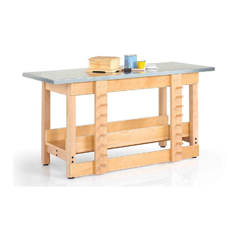
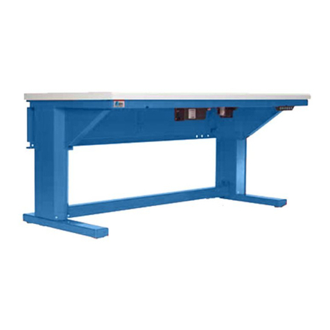
Performax M72WB User manual

USE AND CARE GUIDE
Questions, problems, missing parts?
Before returning to the store, call
9 a.m – 5 p.m., CST, Monday-Friday
1-866-441-5080
Assembly Instructions
Item #211-4794 Model # M72WB
Item #211-4795 Model # M72WBTB
Item #211-4796 Model # M72WBTR
Item #211-4797 Model # M72WBW
72 IN Adjustable Height Workbench With Pegboard

9..............................................................
Operation
Table of Contents
Table of Contents..................................................2
Safety Information ...............................................2-3
Warranty ................................................................4
Specifications ........................................................4
Package Contents..................................................4-5
Assembly ...............................................................6-8
10............................... ................................ecnanetniaM
Safety Information
1.
2.
3. This product is intended for indoor use only.
4.
5.
Do not alter this product in any manner. This product
is not designed for commercial or industrial use.
Do not stand on this product. You
may fall which may cause personal injury or
CAUTION: Keep the product on level surfaces.
The product may become unstable and tip if
stored or moved on an unlevel surface, which
may cause personal injury or product damage.
CAUTION:
CAUTION:
indicates a hazardous situation
which, if not avoided, could result in product
damage or personal injury.
CAUTION:
Read and follow all Safety Rules
and Operating Instructions before first use of
this product.
Replacement Parts ................................................10
product damage.
Cordless Power Tool Battery Chargers ...............9
2
Do not attach or mount this product
to a vehicle or mobile trailers. This may cause
personal injury or product damage. Mounting this
product to any vehicle or mobile trailers in any
warranty.
CAUTION:
manner will void
Use appropriate safety equipment when using power
and hand tools. Failure to do so may cause personal
injury or product damage.
Obtain the aid of an assistant to assemble and move
this unit. Failure to do so may cause personal injury or
product damage.
Check all bolts periodically and tighten if needed.

7. Extension cord
Follow all manufacturers' Warnings and Operating
Instructions for your extension cord.
Only use a three-wire extension cord with all three prongs
intact. Never remove the round grounding prong.
Check the insulation and plugs of extension cord before
using. Do NOT use cord if it is worn or damaged.
□
□
□
□
Do not insert extension cord through hole without grommet
in place.
□
Extension cord must be connected to a 125 Volt GFCI
protected outlet with proper ground. If GFCI outlet is not
available, use an extension cord with GFCI protection
built in.
□
□
□
Do NOT overload extension cord.
Remove extension cord from the hole
before moving or transporting storage cabinet.
Only use an extension cord that is rated for outdoor use.
□Do NOT connect extension cord to outlet that also sup-
plies critical safety equipment with power.
8. Electrical Shock Hazard
□ Do not plug cord into outlet with wet hands.
□ Do not use this product near a bathtub, a shower, or a
swimming pool.
□ Product plugs must match the outlet.
□ Never modify the plug in any way.
□ Do not use any adapter plugs with earth (grounded) cabinet
power strips.
□
of electric shock.
□ Avoid body contact with earthed or grounded surfaces. There
is an increased risk of electric shock if your body is earthed or
grounded.
CAUTION: RISK OF ELECTRICAL SHOCK: This unit has
one power supply cord. Make sure the cord is
unplugged before any servicing or cleaning.
3
NOTE : This equipment has been tested and found to
comply with the limits for a Class B digital device,
pursuant to Part 15 of the FCC Rules. These limits are
designed to provide reasonable protection against
harmful interference in a residential installation. This
equipment generates, uses and can radiate radio
frequency energy and, if not installed and used in
accordance with the instructions, may cause harmful
interference to radio communications.However, there
is no guarantee that interference will not occur in
a particular installation.
If this equipment does cause harmful interference to
radio or television reception, which can be determined
by turning the equipment off and on, the user is
encouraged to try to correct the interference by one or
more of the following measures:
□Reorient or relocate the receiving antenna.
□Increase the separation between the equipment and
receiver.
□Connect the equipment into an outlet on a circuit
different from that to which the receiver is connected.
□Consult the dealer or an experienced radio/TV
technician for help.
NOTE : This device complies with Part 15 of the FCC
Rules. Operation is subject to the following two
conditions: (1) this device may not cause harmful
interference, and
(2) this device must accept any interference received,
including interference that may cause undesired
operation.
WARNING: Changes or modifications to this unit not
expressly approved by the party responsible for
compliance could void the user’s authority to operate
the equipment.
Specifications
Workbench Maximum Load Capacity 2000 lbs.
NOTE: Begin product assembly close to t nal
intended location of your workbench. This product is
heavy and may be di cult to move after assembly.
Package Contents
HARDWARE INCLUDED
NOTE: Hardware not shown to actual size.
ALTERNATIVE TOOLS FOR ASSEMBLY
(Not Included)
4
Limited Lifetime Warranty
PERFORMAX® Workbenches are warranted to be free from defects in materials and workmanship under normal use for the lifetime
that you own the product. If any part of the product is found to be defective during normal use, the defective product or part will be replaced at
our discretion. This warranty does not cover products that are damaged through accident, abuse, misuse, commercial/industrial applications or
neglect. This warranty also does not cover any losses, injuries or costs including indirect, incidental or consequential damages. This warranty
may not be transferred or sold. When requesting warranty service please call 1-866-441-5080 and have the model number, cash register receipt
and the date of purchase available when you call. If the product is defective, we will replace the defective part at no cost to you. Some states
do not allow the exclusion or limitation of incidental damages, so the above limitations or exclusions may not apply to you. This warranty gives
Part Description
AA M6x12 Screw 73
BB M4x12 Screw 2
CC Leveling Feet 4
Quantity
BB CC
AA

Part Description Quantity
A
B
Workbench Wood Table 1
Front Crossbar 1
1Rear CrossbarC
1Left Leg PanelD
Part Description Quantity
G
H
Pegboard 1
L bracket 2
E
Right Leg Panel 1
1Back Rail
F
1Bottle OpenerI
Package Contents (continued)
5
G
H
A
C
D
F
B
E
I

Assembly
Unpacking instructions
CAUTION:
Two people are recommended for assembly.
1
After opening shipping box, remove protective cardboard from the top of the wood table and place cardboard on the floor.
With the aid of an assistant, remove wood table and lay topside down on cardboard to protect the wood from scratching.
□
□
Remove the remainder of workbench parts from shipping box. Check parts and hardware against the PARTS and
HARDWARE lists on the next page. If parts or hardware are missing, please call 1-866-441-5080 for assistance.
□
Attaching the Leveling Feet
2
Attach the four Leveling Feet (CC) to the Left (D) and
Right Leg Panels (E) and tighten.
□
6
ED
CC
3Workbench Height Adjustment
□
Completely unscrew the Screws (AA) from each
Leg Panel as shown in figure below.
□
Raise or lower the leg bottoms to the same position
in the leg channels on each Leg Panel.
□
Insert and securely tighten the previously removed
□
Ensure 8 Screws (AA) are used to secure the Leg Panels.
screws.
The Leg Panels are pre-set for a total workbench height
of 36 inches (not including leveling feet).
The Leg Panels can be adjusted to alter the workbench
height from 32 inches to 42 inches.
Leg bottom
Leg channel
AA

Attaching the Crossbars
5
The Front Crossbar (B) has PREFORMAX badge.
□
Attach Front Crossbar (B) to front of Table
and Rear Crossbar (C) to back of Table
□
Align the pre-drilled holes in Table with
holes in Crossbar length.
□
Partially tighten Screws (AA) through each
Crossbar (B,C) into Table .
□
Align Crossbar (B,C) end holes with holes in
Left and Right Legs (D, E).
□
On each end of Crossbar, partially tighten
screws (AA) through Crossbar holes into
Leg holes as shown in figure below.
Note: The Crossbar end flanges must be
attached so that they are on the outside
of the Leg Panels.
□
Go back and tighten all Screws (AA)
□
Attaching the Wood Table
4
Determine the front and back of table. Leg Panels
must be attached to the table with Back Rail attachment
holes to the back of table.
□
Attach the Left (D) and Right Leg Panels (E) to the
underside of the Workbench Table (A):
□
Align the pre-drilled holes in Table with holes in top
of Legs.
□
Partially tighten 3 Screws (AA) through each Leg into the
Table as shown in the figure below. Do not fully tighten
the Screws to allow for proper installation of the Crossbar
attachments.
□
7
A
Underside of Workbench Table
Table Front
Table Back
DE
C
D
B
AA
E
CAUTION:
Ensure all Screws are properly tightened before flipping the Workbench over.

Attaching the L bracket
8
Position the L-bracket (H) over the holes on
the Pegboard (G) and the workbench.
□
Tighten 6 Screws (AA) through the L-bracket (H)
into Pegboard (G) and the workbench.
□
Repeat this process for the other side of the
Pegboard (G) to attach it to the workbench.
□
□
8
G
H
AA
Attaching the Pegboard
7
Attaching the Back Rail
6
With the help of another person,
□
□
□
carefully lift the Pegboard (G) into the
upright position as shown.
Align Pegboard (G) end holes with holes in
Rear Crossbar (C).
□
Install and tighten 11 Screws (AA) through
Pegboard (G) holes into Rear Crossbar (C) holes
as shown in the figure.
□
AA
Attach Back Rail (F) to back of Left and Right Leg Panel (D,E).
Align Back Rail end holes with holes in back of Left and
Right Legs.
Install and tighten 4 Screws (AA) through Back Rail end holes
into Leg holes as shown in figure below.
Note: The Back Rail end flanges must be attached so that
they are on the outside of the Leg Panels.
F
AA
Once the L bracket is attached, go back and
fully tighten all screws.
G

Cordless Power Tool Battery Chargers
See Charger’s Owner’s Manual for proper use and care of charger and batteries.
Follow all Warnings and Instructions provided with your battery charger.
□
Chargers are for use in dry locations only. Do NOT expose to liquid, vapor, or rain. Should your charger become wet,
Do NOT attempt to use. Unplug extension cord from supply before handling wet charger or cords.
□
Only use chargers and batteries that are intact and operating properly.
□
Do NOT touch metal prongs when plugging charger into extension cord.
□
□
Do NOT place or attempt to charge lead acid, car type batteries.
□
1
□
Attaching the Bottle Opener
9
BB
IB
Leveling Foot Adjustment
Adjust leveling position by turning the foot nut left to raise
and right to lower the foot. Raise Lower
Foot Nut
Operation
9
Tighten 2 Screws (BB) through the Bottle Opener (I)
holes into Front Crossbar (B) holes as shown
in the figure.
□

□
Maintenance
Periodically the surfaces should be cleaned with a mild detergent and water.
Replacement Parts
For assistance with replacement parts please call 1-866-441-5080.
Part Description Quantity
B
L bracket 2
ALeveling Feet 4
C
M6x12 Screw 73
D
Bottle Opener 1
1
2M4x12 Screw
E
F
10
A
D
E
C
B
F
Power Strip
This manual suits for next models
7
Table of contents
Other Performax Tools Storage manuals