4 1-800-732-2677
Thank you for choosing PetSafe®brand. You and your pet deserve a companionship that includes
memorable moments and a shared understanding together. Our products and training tools
promote a lifestyle of protection, teaching, and love — essentials that influence memories for a
lifetime. If you have any questions about our products or training your pet, please visit our website
at www.petsafe.net or contact our Customer Care Center at 1-800-732-2677.
To get the most protection out of your warranty, please register your product within 30 days
at www.petsafe.net. By registering and keeping your receipt, you will enjoy the product’s full
warranty and should you ever need to call the Customer Care Center, we will be able to help
you faster. Most importantly, PetSafe®will never give or sell your valuable information to anyone.
Complete warranty information is available online at www.petsafe.net.
Table of Contents
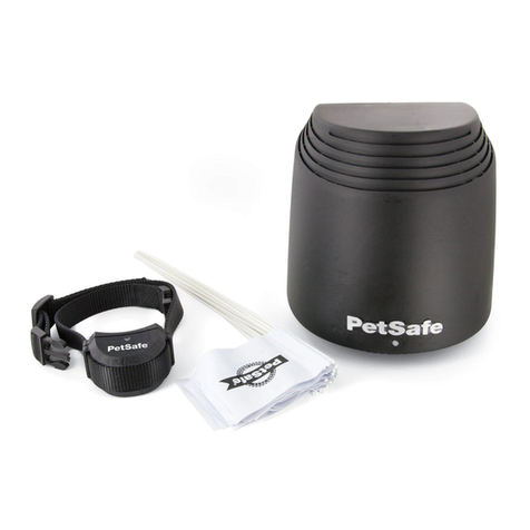
Components....................................................................................................................................................................................... 5
Other Items You May Need ............................................................................................................................................................... 5
How the System Works ...................................................................................................................................................................... 6
Key Definitions ................................................................................................................................................................................... 6
Operating Guide .......................................................................................................................................... 7
Lay out the System.......................................................................................................................................................................... 8
Set Up the Transmitter.................................................................................................................................................................. 11
Charge the Receiver Collar........................................................................................................................................................... 11
Prepare the Boundary Programming Unit .................................................................................................................................... 12
Prepare the Receiver Collar for Programming.............................................................................................................................. 12
Place the Boundary Flags.............................................................................................................................................................. 13
Programming the Boundary.......................................................................................................................................................... 13
Test the Receiver Collar ................................................................................................................................................................ 14
Prepare the Receiver Collar .......................................................................................................................................................... 15
Fit the Receiver Collar................................................................................................................................................................... 18
Training Guide ............................................................................................................................................ 20
Be Patient With Your Pet............................................................................................................................................................... 20
Day 1 - Boundary Awareness ........................................................................................................................................................ 21
Days 2 thru 4 - Continue Boundary Awareness ............................................................................................................................ 22
Days 5 thru 8 - Distraction Phase.................................................................................................................................................. 22
Days 9 thru 14 - Unleashed Supervision ....................................................................................................................................... 23
Days 15 thru 30 - Pet Monitoring ................................................................................................................................................. 23
Taking Your Pet Out of the Pet Area................................................................................................................................................ 23
Accessories....................................................................................................................................................................................... 24
Frequently Asked Questions............................................................................................................... 24
Troubleshooting......................................................................................................................................... 25
Terms of Use and Limitation of Liability .......................................................................................................................................... 27
Compliance ...................................................................................................................................................................................... 27
Customer Care International............................................................................................................................................................ 27
