HD3600/20/B
3-15
Replacing the Peltier element:
- When the Peltier element has to be replaced, first remove
the rear case assy and Fan assy.
- Unscrew the 2 screws located on the heat sink.
- The heat sink including Peltier element can now be
removed.
- With a small screwdriver the Peltier element can be removed
from the heat sink, some force maybe needed.
- Before placing the new Peltier element, provide heat sink
paste on both side of the Peltier element.
- Place the new Peltier element on the cooler plate on the
same position of the removed Peltier element.
NOTE! It is important to place the Peltier element with
the right side on the COOLER PLATE.
- The cooler plate is the aluminium part fixed in the
appliance, where the KEG will be cooled on.
- The heat sink is the aluminium part where the fan is
assembled on.
- In other words, the cooling side of the Peltier has to point
to the COOLER PLATE and the warm side has to point to
the HEAT SINK.
- Details to check are:
• Soldered joints must be pointing
to the cooling plate.
(when Peltier is placed on the
cooler plate the soldered joints
are not visible, seen from the
backside)
• Colours of wires must be equal
positioned see, picture for detail.
- Be careful and make sure the Peltier element is well placed.
- Now the heat sink can be placed on the peltier element.
- Tighten the screws alternate, to prevent damaging the
Peltier element for mounting lop-sided.
- Maximum force that maybe applied to tighten the screws
are: 0.6 Nm.
Procedure for checking cool down
performance Peltier element.
To ensure the Cool performance of the Peltier element is
according specification the below test procedure have to be
carried out.
- Preparations:
1. Switch the appliance off and let it stabilize until it
reached room temperature.
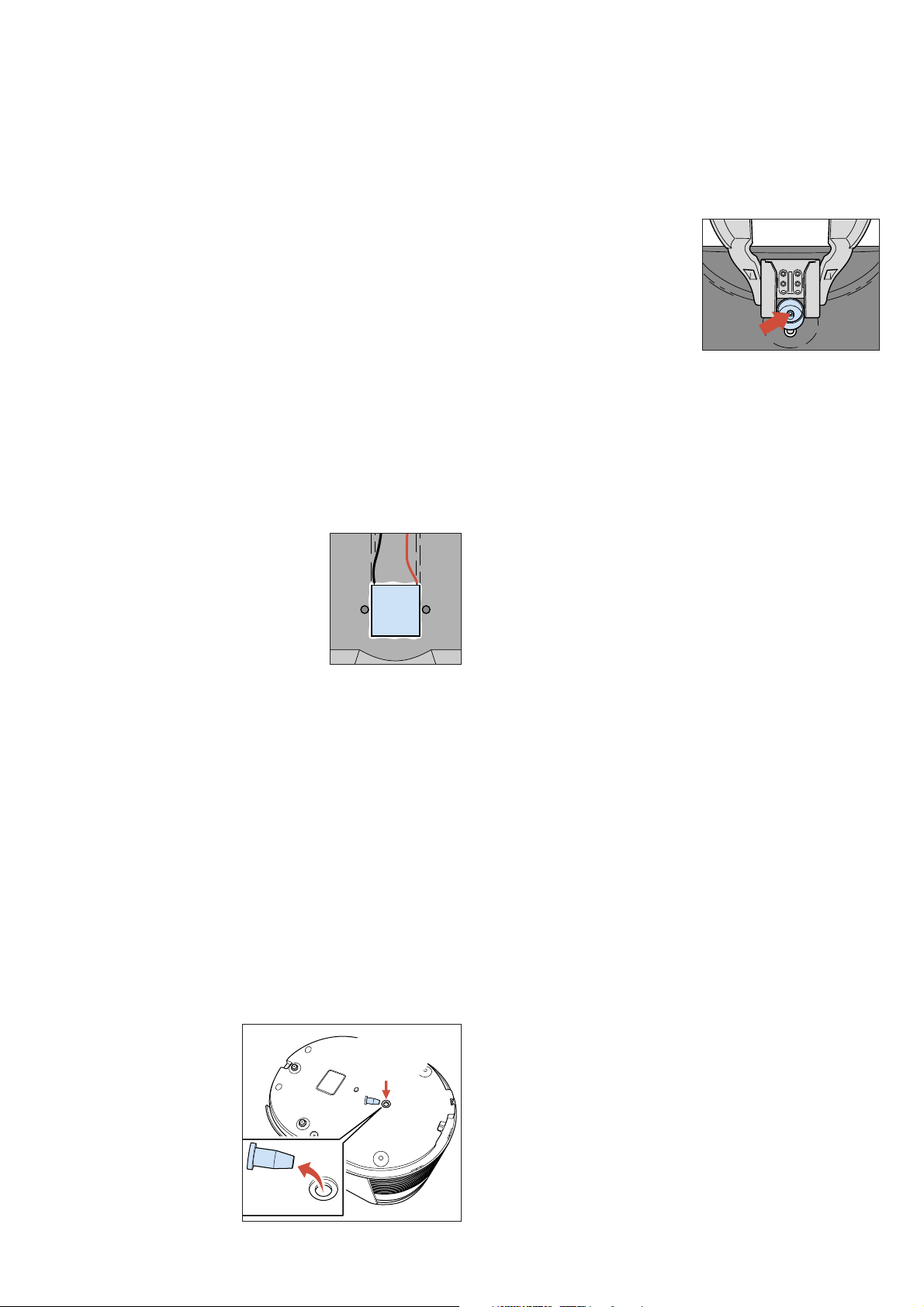
2. Remove under the base in the middle the rubber Cap.
3. The chiller plate
becomes visible.
DISASSEMBLY- AND RE-ASSEMBLY ADVISE
- Performing the temperature measurement, when the unit
has reached the room/environment temperature.
1. Place a contact temperature probe against the chiller
plate where the rubber cap was removed.
2. Block the air inlet
coupling at the Keg
side, see picture 6 for
location.
3. Plug the appliance in the wall socket and bridge over
the Keg present switch mechanically or electrically so
the appliance will start.
4. When the appliance has started the pump will run
shortly (in case the air inlet has been blocked properly)
5. Readout the temperature meter and note it down.
6. Keep the appliance switched on for 2 minutes, readout
the temperature again.
7. If the temperature has decreased more then 6 °C,
between the two measurements the cooling works fine,
if not please check again or replace Peltier or Fan assy.
- Final:
When the appliance is checked and OK, place the rubber
Cap back under the base.
Replacing pressure sensor PCB:
- To replace the pressure sensor PCB assy, situated on the
pump, unscrew the 2 screws completely.
- Disconnect the connector, gently turn the PCB assy left and
right and at the same time pull the unit up.
Sometimes also the side cap must be unscrewed a little to be
able to remove the pressure sensor.
- Place the new PCB assy and check if the small rubber ring
on the sensor tube is on its place.
Replacing the pump unit:
- Start with disconnecting the air pressure hose and electrical
connections.
- Unscrew the 3 screws from the plastic bracket were the
pump unit is hanging on.
- To re-assembly carry out steps backwards.
NOTE! To prevent leakage at the connection side of the
hose, cut a small piece off the end of the hose.
Picture 4.
rubber
Cap
contact
temperature
probe
Picture 5.
Picture 6.