manuals.online logo
Brands
  1. Home
  2. •
  3. Brands
  4. •
  5. Philips
  6. •
  7. Recording Equipment
  8. •
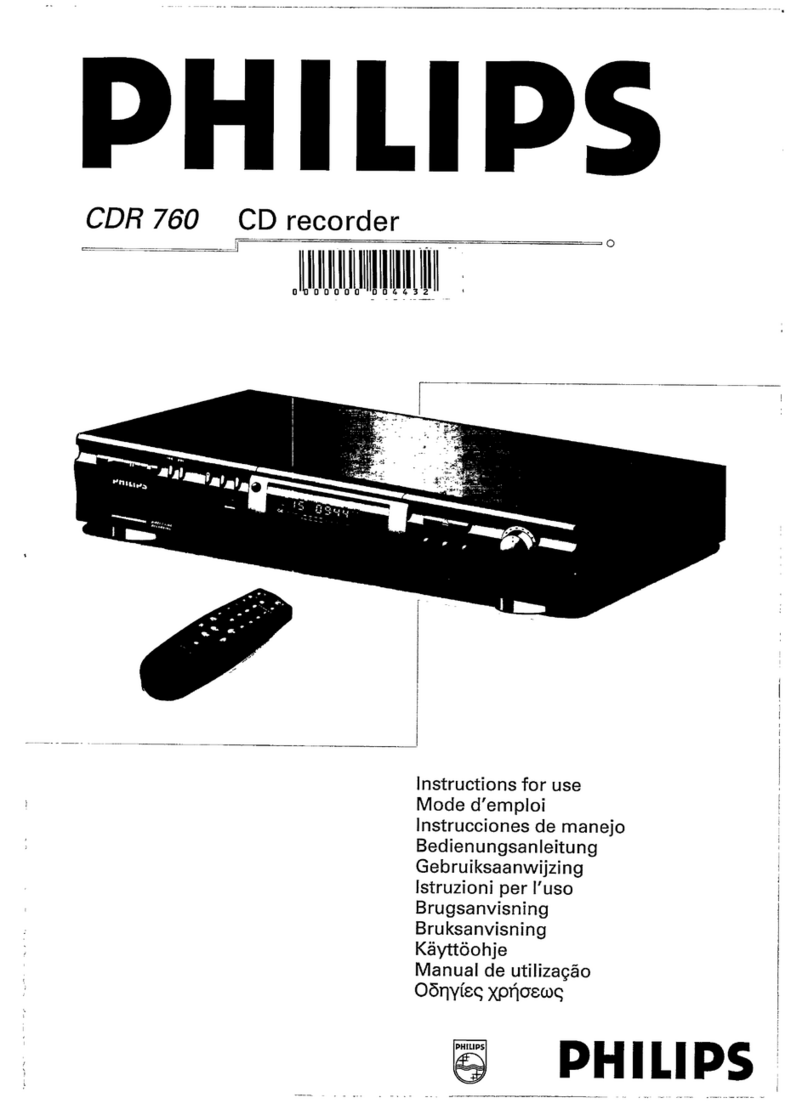
  9. Philips CDR-775 User manual

Philips CDR-775 User manual

Compactdiscrecorder CDR775
Service
/oo
nCOJJPACTriBOMfWCTnOOMPACTHCOMPACT
togl
(ta
oEtascB
GQD§(S
SERVICING
ForservicingCDR775,thesetcandividedintothreeparts.
1.
Thedisplayboard(partly)
1
002,theI/Oboard1004,the
headphoneboard(partly)
1002,
theIRboard(partly)1002,theON/
OFF& StandbyLEDboard(partly)1002andtheCD-outboard
(partly)1002havetoberepairedatcomponentlevel.Thepower
supplyunit1003isavailableassparepart,butcanalsoberepaired
atcomponentlevel.
2.
TheCDRmodule(containingtheCDRloader
81,
CDRmainboard
1001andloaderbracket82,83)willbeexchangedcompletelyin
caseoffailure.ThiscompleteCDRmoduleisavailableasspare
part.Defectivemoduleshavetobereturnedforcentralrepair.
3.TheCDmodule(containingtheCDloader
131,
CDmainboard
1005andloaderbracket132)isa newmodulewithVAL1250
loaderassybutalsoaseparateCDMandseparateloader
parts
will
beavailableviaservicestock.TheCDmainboardcanberepaired
atcomponentlevel.
Alsoavailable:CircuitDescription" TheBasicsofCompactDisc
Recordable/Rewriteable".Servicecodenumber482272525242.
Copyrightreserved1999PhilipsConsumerElectronicsB.V.Eindhoven,The
Netherlands.Allrightsreserved.Nopartofthispublicationmaybereproduced,
storedinaretrievalsystemor
transmitted,
inany
form
or
by
any
means,
electronic,
mechanical,photocopying,orotherwisewithoutthepriorpermissionofPhilips.
MOfTAlAUOtOMBtTAlAUDIO PtGfTAlAUMOOHHTALAUDIO
Contents
1.
TechnicalSpecifications
2.
WarningandServicingHints
3.UserInstructions
4.
MechanicalInstructions
WiringDiagramCDR
WiringDiagramCDloader
ExplodedViewCDR
ExplodedViewCDloader
DismantlingInstructions
5.ElectricalandCircuitDiagrams
OverallBlockdiagram
DisplayBoard
IR/ On/Off&StandbyLEDBoard
Headphone/ CD-outBoard
I/OBoard
Powersupplyunit
CD-Mainboard1A
CD-Mainboard1B
CD-Mainboard1C
CD-Mainboard2
6.DiagnosticSoftware
7.FaultfindingTrees
8.FaultfindingGuide
9.ListofAbbreviations
10.
Partslist(mechanicalandelectrical)
Page
2
4
7
19
19
20
21
22
23
Diagram PWB
24
26
27
28
29
31
33
34
35
36
39
43
49
65
71
26
27
28
30
32
37/38
37/38
37/38
37/38
PublishedbyRH9969ServiceDPSHasselt PrintedintheNetherlands Subjecttomodification <§§>310412540030
PHILIPS
WarningsandServicingHints
SERVICINGHINTS
Intheset,chipcomponentshavebeenapplied.Fordisassemblyandassemblycheckthefigurebelow.
CL96532086_022.eps
080999
CDR775 WarningsandServicingHints
SAFETYGUIDELINESFORTHEPROFESSIONALSERVICETECHNICIAN
Important
ProperserviceandrepairisImportanttothesafe,reliableoperation
ofallPhilipsequipment.Theserviceproceduresrecommendedby
PhilipsanddescribedInthisservicemanualareeffectivemethodsof
performingserviceoperations.Someoftheseserviceoperations
requiretheuseoftoolsspeciallydesignedforthepurpose.The
specialtoolsshouldbeusedwhenandasrecommended,
ItisImportanttonotethatthismanualcontainsvariousCAUTIONS
andNOTICESwhichshouldbecarefullyreadInordertominimizethe
riskofpersonalinjurytoservicepersonnel.Thepossibilityexists
thatImproperservicemethodsmaydamagetheequipment.Italso
IsImportanttounderstandthattheseCAUTIONSandNOTICES
ARENOTEXHAUSTIVE,Philipscouldnotpossiblyknow,evaluate
andadvisetheservicetradeofallconceivablewaysInwhichservice
mightbedoneorofthepossiblehazardousconsequencesofeach
way.Consequently,Philipshasnotundertakenanysuchbroad
evaluation.
Accordingly,a servicerwhousesa serviceprocedureor
toolwhichIsnotrecommendedbyPhilipsmustfirstsatisfyhimself
thoroughlythatneitherhissafetynorthesafeoperationofthe
equipmentwillbeJeopardizedbytheservicemethodselected.
SafetyChecks
Aftertheoriginalserviceproblemhasbeencorrected,a complete
safetycheckshouldbemade.Besuretocheckovertheentireset,
notJusttheareaswhereyouhaveworked.Somepreviousservicer
mayhaveleftanunsafecondition,whichcouldbeunknowingly
passedontoyourcustomer.Besuretocheckallofthefollowing:
FireandShockHazard
1.
BesureallcomponentsarepositionedInsucha wayastoavoid
thepossibilityofadjacentcomponentshorts.Thisisespecially
importantonthoseunitswhicharetransportedtoandfromthe
serviceshop.
2.
Neverreleasea repairedunitunlessallprotectivedevicessuch
asinsulators,barriers,covers,strainreliefs,andother
hardwarehavebeeninstalledaccordingtotheoriginaldesign,
3.Solderingandwiringmustbeinspectedtolocatepossiblecold
solderJoints,soldersplashes,sharpsolderpoints,frayed
leads,
pinchedleads,ordamagedInsulation(Includingtheac
cord).
BecertaintoremoveloosesolderballsandaHother
looseforeignparticles.
4.
Checkacross-the-linecomponentsandothercomponentsfor
physicalevidenceofdamageordeteriorationandreplaceif
necessary.Followoriginallayout,leadlength,anddress.
5.Noleadorcomponentshouldtoucha resistorratedat
1
wattor
more.
Leadtensionaroundprotrudingmetalsurfacesoredges
mustbeavoided.
6.Criticalcomponentshavingspecialsafetycharacteristicsare
Identifiedwitha AbytheRef.No.Inthepartslistandenclosed
withina brokenline*(whereseveralcriticalcomponentsare
groupedInonearea)alongwiththesafetysymbol
Aontheschematicdiagramsand/orexplodedviews.
Replacementpartswithoutthesamesafetycharacteristics
maycreateshock,fire,orotherhazards.
7.Whenservicinganyunit,alwaysusea separateIsolation
transformerforthechassis.Failuretousea separateisolation
transformermayexposeyoutopossibleshockhazard,and
maycausedamagetoservicinginstruments.
8.Manyelectronicproductsusea polarizedaclinecord(onewide
pinontheplug).Defeatingthissafetyfeaturemaycreatea
potentialhazardtotheservicerandtheuser.Extensioncords
whichdonotIncorporatethepolarizingfeatureshouldn»ver be
used.
FireandShockHazard(Continued)
9,Afterreassemblyoftheunit,alwaysperformanacleakage
testorresistancetestfromthelinecordtoallexposedmetal
partsofthecabinet,Also,checkallmetalcontrolshafts(with
knobsremoved),antennaterminals,handles,screws,etc.to
besuretheunitIssafetooperatewithoutdangerofelectrical
shock,
Brokenline:an
LeakageCurrentColdCheck
1,
Unplugtheaclinecordandconnecta Jumperbetweenthetwo
prongsofthe
plug,
Turnonthepowerswitch.
MeasuretheresistancevaluebetweentheJumperedacplug
andallexposedcabinetpartsofthereceiver,suchasscrew
heads,antennas,andcontrolshafts.Whentheexposed
metallicparthasa returnpathtothechassis,thereading
shouldbebetween1 megohmand5.2megohms.Whenthe
exposedmetaldoesnothavea returnpathtothechassis,the
readingmustbeInfinity.Removethejumperfromtheacline
cord.
TO
INSTRUMENTS
EXPOSED
METALPARTS
1500H,
10VV
WATER
PIPE
(EARTH
GROUND)
LeakageCurrentHotCheck
1.
Donotuseanisolationtransformerforthistest.Plugthe
completelyreassembledunitdirectlyintotheacoutlet.
2.
Connecta 1.5k,10Wresistorparalleledbya 0,15uF.capacitor
betweeneachexposedmetalliccabinetpartanda goodearth
groundsuchasa waterpipe,asshownabove.
3.Useanacvoltmeterwithatleast5000ohms/voltsensitivityto
measurethepotentialacrosstheresistor.
4.
Thepotentialatanypointshouldnotexceed0.75volts.A
leakagecurrenttestermaybeusedtomakethistest;leakage
currentmustnotexceed0.5mllllamps.Ifa measurementIs
outsideofthespecifiedlimits,thereIsa possibilityofshock
hazard.
Thereceivershouldberepairedandrecheckedbefore
returningIttothecustomer.
5.Repeattheaboveprocedurewiththeacplugreversed.(Note:
AnacadapterIsnecessarywhena polarizedplugIsused.Do
notdefeatthepolarizingfeatureoftheplug.)
PartsReplacement
1.
ManyelectricalandmechanicalpartsInPhilipsequipmenthave
specialsafetyrelatedcharacteristics.Thesecharacteristics
areoftennotevidentfromvisualinspectionnorcanthe
protectionaffordedbythemnecessarilybeobtainedbyusing
replacementcomponentsratedforhighervoltage,wattage,
etc.Theuseofa substitutepartwhichdoesnothavethesame
safetycharacteristicsasthePhilipsrecommended
replacementpartshowninthisservicemanualmaycreate
shock,fire,orotherhazards.Undernocircumstancesshould
theoriginaldesignbemodifiedoralteredwithoutwritten
permissionfromPhilips.Philipsassumesnoliability,expressor
implied,
arisingoutofanyunauthorizedmodificationofdesign.
Servicerassumesallliability.
2.
AllICsandmanyothersemiconductorpartsaresusceptibleto
electrostaticdischarges(ESD).Carelesshandlingduring
repaircanreducethelifeofthepartdrastically.
LASERNOTE:
DANGER- Invisiblelaserradiationwhenopen.AVOIDDIRECTEXPOSURETOBEAM.
CAUTION- Useofcontrolsoradjustmentsorperformanceofproceduresotherthanthosespecifiedhereinmayresultinhazardous
radiationexposure.
CAUTION- TheuseofopticalInstrumentswiththisproductwillIncreaseeyehazard.
CL96532086_023.eps
080999
6.2.2Requirementstoperformthetest
•Workingkeyboardtostartupthetest.
•Workinglocaldisplaytochecktheoutputmessages.
CL96532086-024.eps
090999
Figure6-1
6.2.1Description
Theintentionofthedealerdiagnosticsistogiveanindication
oftheCDRplayerstatus.Aninexperienced,even
non-
technicaldealerwill/canperformthetest.Testsareexecuted
automaticallywithoutneedforexternaltoolsordisassemblyof
theunit.ThistestcheckstheCDRmainboardusingthesame
testsastheelectricalservicediagnosticsprogram.Onlythe
resultof
the
test,
"PASSED"or"ERROR",will
be
shownonthe
display.Pressingkeys[FFWD]and[REWIND]simultaneously
whileswitchingontheunit,startsthetest.Switchingoff
the
unit
endsthetest.
DiagnosticSoftware
6.DiagnosticSoftware
6.1Dealermode
Thepurposeofthedealermodeistopreventpeopletakingout
theCDinsidetheplayeratexhibitions,showroomsetc..This
modedisablestheopen/closefunctionoftheplayer,
Thedealermodecanbeswitchedonandoffpressingkeys
[OPEN/CLOSE]and[STOP]of
the
CDRplayersimultaneously
whileswitchingontheunit.Thedealermodeisstoredinthe
flashmemory
and
canonlybechangedbyexecutingtheabove
actions.
6.2Dealerdiagnostics
CDB775 DiagnosticSoftware
6.3Electricalservicediagnostics
ELECTRICALSERVICEDIAGNOSTICS
(software
versions,
testfordefectivecomponents)
Figure6-2
DiagnosticSoftware CDR775
6.3.1Description
Theintentionoftheelectricalservicediagnosticsistoshowthe
softwareversionspresentintheplayerandtodirectthedealer
towardsdefectiveinternalunits.Theunitsare: theCDRmain
board,
theCDRloader,theCDloader
in
caseof
a
CDR775and
thekeyboard/displayboard.A sequenceoftestsisexecuted
automatically.Someofthetestscanbeabortedorskipped
withouttheresultbeingtakenIntoaccount.Externaltoolsor
disassemblyoftheunitisnotnecessarytogetthediagnostic
information.Pressingkeys[PLAY/PAUSE]and[FFWD]
simultaneouslywhileswitchingontheunit,startsthetest.
Switchingofftheunitendsthetest.
6.3.2Requirementstoperformthetest
•Workingkeyboardtostartupthetest.
•Workinglocaldisplaytochecktheoutputmessages.
•A CD-DAdiscwitha minimumof3tracksinalltraysto
performthedisctest.
6.3.3Descriptionofthetests
disctestisexecutedtocheckfocuscontrol,discmotorcontrol,
radialcontrolandjumpgroovescontrol.Thedisctestis
performedbyaudioplay-backof5 secondsatthebeginning,
middleandendofthedisc.
CDR
loader
test
Duringthetest,thecurrentdisctimeisshown.Incaseofan
errorthemessage
"BERR1"
willbedisplayedandthe[FFWD]
keymustbepressedtocontinuewiththefollowingtest.
Pressingthe[FFWD]keyalsoabortsthistest.
CDloader
test
ForCDR775only.Duringthetest,thecurrentdisctimeis
shown.
Incaseofanerrorthemessage"BERR2"willbe
displayedandthe[FFWD]keymustbepressedtocontinue
withthefollowingtest.Pressingthe[FFWD]keyalsoaborts
thistest.
Display test
Allsegmentswillblinkata frequencyof
1
Hz.Pressingthe[F
FWD]keywillstartthenexttestbecausetheuserhastocheck
forhimselfifallsegmentsworkproperly.
Player
Information
Inthispartof
the
testthefollowingImportantInformationcanbe
checkedwithoutremovingthecover:
RecorderID.
•SW-versionbackendofplayer.
SW-versionCDRloader.
•SW-versionCDloader(onlyforCDR775).
CDRmain board
test
[FFWD]key.Themessage"DERRn"willbedisplayedwithn
indicatingthefaultytestnumber.
Ifoneofthetestsisabortedwiththe[FFWD]key,noerror
messagewillbedisplayedforthistest.Theflashdataerase
test
("DTST3")
cannotbeaborted!
TheCDRmainboardtestconsistsoutof:
DRAM test
Display:
"DTST1",
TheDRAMusedforbuffermanagementis
testedbywriting,readingandverifyingtestpatterns.
Flash
checksum
test
Display: "DTST2".Thistestchecksthechecksumofthe
player'sSWstoredintheflash.
Flash data erase
Display: "DTST3".Duringthistest,alltemporaryinformation
(CDtxt)intheflashiserased.
CODEC
(ADC/DAC)
test
Display: "DTST4".ThistestcheckstheCODECICbywriting,
readingandverifyingtest
patterns.
Thetestisnotapplicablefor
CDR950.
Keyboard
and
remote
control tests
Thetestwillgivetheusertheabilitytotesteverykeywithout
executingthefunctionassignedto
it.
Therefore,theuserneeds
topresseverykey
on
thekeyboardandtheremote
control.
The
displaywillshowthenameofthekeybeingpressed.Pressing
morethanonekeyatoncewillgiveanunpredictableresult
exceptfor
the
servicecombinations:[PLAY/PAUSE]+[STOP],
[PLAY/PAUSE]+ [FFWD],[FFWD]+ [REWIND],[ERASE]+
[RECORD],[PLAY/PAUSE]+ [RECORD],[OPEN/CLOSE]+
[PROGRAM].
6.4Mechanicalservicediagnostics
CDR
communication
test
Display: "DTST5".Thecommunicationbetweenthehost
processor(DASP)andtheCDRloaderviatheDSA-R-busis
tested.
CD
communication
test
Display: "DTST6").Thecommunicationbetweenthehost
processor(DASP)andtheCDloaderis
tested.
Thetestisonly
applicableforCDR775.
Loader tests
ThesetestsdetermineiftheCDRloaderandtheCDloaderin
caseofa CDR775workcorrectly.A CD-DAdiscwitha
minimumof3 tracksneedstobeinsertedinbothloaders.A
6.4.1Description
Noexternaltoolsarerequiredtoperformthistest.Thecover
needstoberemovedbecausetheuserhastocheckthe
movementsofthetray,focusandsledgevisually.Pressing
keys[PLAY/PAUSE]and[STOP]simultaneouslywhile
switchingontheunit,startsthe
test.
Switchingofftheunitends
thetest.Incaseofa CDR775,onecanchecktheCDloader
mechanicsinthesamewaybypressingtheabovekey
combinationontheCDplayerkeys.
BSEMHH
IHQ^^HHDiagnosticSoftware
6.4.2Requirementstoperformthetest
•Workingkeyboardtocyclethroughthetestsandtostartup
thetest.
Workinglocaldisplaytochecktheoutputmessages.
6.4.3Descriptionofthetests
Focus control test
Thefocussinglensiscontinuouslymovingupanddown.The
displayreads"BUSY".
Sledge control test
Afterpressing[FFWD]thesledgecontinuouslymovesupand
down.
Pressing[REWIND]stopsthesledgeatthepositionitis
inandthefocuscontroltestresumes.Thedisplayreads
"BUSY".
Tray control test
Thisteststartsfromwithinthefocuscontroltestroutine.
Pressing[OPEN/CLOSE]movesthetrayinorout.Inthetray
openpositiononecaninitiatefocusandsledgetestsby
pressing[F
FWD].
Onehastostopthesetestspressing
[REWIND]beforeitispossibletoclosethetrayagain.
Dependingontheactionthedisplayreads"OPEN",
"OPENED",
"CLOSE"or"BUSY".
6.5DC-eraseservicemode
i.5.1Description
Thistestisinitiatedbypressing[ERASE]and[RECORD]
simultaneouslywhileswitchingontheunit.Theplayerwill
erasea completeCD-RWdisc(includingPMAandATIPlead
outarea)atspeedN=2.Thedisplayshowsthecountdownof
theremainingtimerequiredfortheoperationtocomplete,The
formatis"ERmm:ss",where"mm"aretheremainingminutes
and
"ss"
theremainingseconds.Aftercompletionthemessage
"PASSED"
isshown,andtheplayerhastobeswitchedoffand
onagaintostartupinnormaloperating
mode.
Switchingoffthe
unitbeforecompletionofthetest,leavesthediscinan
unpredictablestate.Insuchcaseonlya completeDC-erase
procedurecanrecovertheCD-RWdisc.
5.5.2Requirementstoperformthetest
••FunctionalCDRplayer.
*A CD-RWaudiodiscmustbepresentinthetray.
Figure6-4
Faultfindingtrees
7.Faultfindingtrees
CDR775
7.1CDR-Module
Figure7-1
CDR775 Faultfindingtrees
Figure
7-2
Faultfindingtrees CDR775
Figure
7-3
CDR775 Faultfindingtrees
Faultfindingtrees
7.2CDModule
C0R775 •pMiiiap»|»iMM
Figure7-5
CDR775 Faultfindingtrees
FaultfindingGuide
8.FaultfindingGuide
CDR775
8.1DisplayBoard
8.1.1Description
of
displayboard
General description
Thedisplayboardhasthreemajorparts
:
theFTD(Fluorescent
TubeDisplay),thedisplaycontrollerTMP87C874Fand
the
keyboard.
ThedisplaycontrollerIscontrolledbytheDASP
masterprocessor
on
theCDRmain
board.
Thecommunication
protocolused
is
I2C.SoalltheinformationbetweenDASPand
displaycontrollergoesviatheSDA
or
I2CDATAandSCLor
I2CCLKlines.CommunicationisalwaysinitiatedbytheDASP
ontheCDRmainboard.Unlikethepreviousgenerations
of
CDRplayers,theinterruptgeneratedbythedisplaycontroller
atkey-pressorreceptionofremotecontrolisnot
used.
Instead,
theDASPpollsthedisplaycontrollerfortheseevents.
Display controller TMP87C874F
TMP87C874F(IC7104)Isa highspeedandhighperformance
8-bit
singlechipmicroprocessor,containing
8-bit
A/D
conversioninputsand
a
VFT(VacuumFluorescentTube)
driver.Inthisapplication,itsfunctionsare
:
•slavemicroprocessor.
•FTDdriver,
•generatesthesquarewaveforthefilamentvoltage
requiredforanACFTD.
•generatesthegridandsegmentscanningfortheFTD.
•generatesthescanninggrid
for
thekeymatrix.
•input
for
remotecontrol.
All
thecommunicationrunsviatheserialbusinterfaceI2C.The
displaycontrollerusesan8MHzresonatorasclockdriver.
PINDESCRIPTIONS
INTO
INT1
RESETN
SCL
SDA
TEST
VAREF
VASS
VDD
VKK
VSS
XIN,
XOUT
externalinterruptinput0
externalinterruptinput1
resetsignalinput,activelow
l2C-busserialclockinput/output
l2C-busserialdatainput/output
testpin,tiedtolow
analogreferencevoltageinput
analogreferenceground
+5V
VFTdriverpowersupply
ground
resonatorconnectingpinsforhigh-frequencyclock
CL96532076_028.eps
290799
Figure8-1
CDR775 FaultfindingGuide
8.1.2Testinstructions
Supply
voltages
Thedisplayboardreceivesseveralvoltagesviaconnector
1119(andconnector
1121
forCDR570/930).
•VFTD: -38V±5%measuredatpin2 ofconn.1119.
•VDC1-VDC2
:
3V8
±10%
measuredbetweenpin
1
and3 of
conn.
1119.
•+5V:+5V±5%measuredatpin10of
conn.
1119(pin4 of
conn.
1121forCDR770).
VoltagesVFTD,VDC1andVDC2areproducedinthepower
supplyunitandsenttothedisplayboardviatheCDRmain
board.
The+5VvoltageisproducedontheCDRmainboardas
D5V.
Clock
signal
Asclockdriverforthedisplaycontroller,a resonatorof8MHz
(1110)isused.Thesignalcanbemeasuredatpins8 and9 of
thedisplaycontroller:8 MHz±5%.
Control signals
RESET
Theresetsignalcomesviapin4 ofconn.1119fromtheDASP
masterprocessor
on
theCDRmainboard(SYS_RESET).The
resetislowactive.Itshouldbekeptlowduringpowerupforat
least3 machinecycleswithsupplyvoltageinoperatingrange
anda stableclocksignal
(1
machinecycles12x
1/Fc(8MHz)
sec).
Duringnormal
operation,
theresetshouldbehigh(3V3).
Thehighsignalis3V3becausetheDASPoperateson3V3.
I2CDA
TA/I2C
CLK
TheselinesconnecttotheDASPmasterprocessorvia
respectivelypin5 andpin7 of
conn.
1119(pin5 of
conn.
1119
andpin
1
ofconn.1121forCDR570/930).WhenthereIsno
communication,theyshouldhavethehighlevel(+5V),The
oscillogrambelowgivesanindicationofhowthesesignals
shouldlooklike.
Grid lines
Levelandtimingofallgridlines,G1-->G15,canbechecked
eitherattheFTDitselforatthedisplaycontroller.Gridlines
G13,
G14andG15eachhaveanextracurrentamplifierinline
:T7203forG13,T7204forG14andT7100forG15,A typical
gridlinesignalshowsintheoscillogrambelow.
Figure8-3'Gridline'
Segment lines
Levelandtimingofallsegmentlines,P1-->P21(P1-->P20for
CDR770),canbecheckedeitherattheFTDitselforatthe
displaycontroller.Thedataonthesesegmentlineshowever,
dependsonthecharactersdisplayed.Theoscillogrambelow
showsa segmentlinewithdata.A segmentlinewithoutdata
maintainsa -38Vlevel.
Figure8-2'I2Csignals'
FTD drive lines
Filament voltage
Shouldmeasure3.8V±10%
(=VDC1
-VDC2)betweenpins
1
-2-
3andpins45-46-47(pins1-2andpins48-49forCDR770)of
theFTD(1113).
Figure8-4'Segmentline'
Key matrix lines
Thelinesconnectedtopins34,35,36and37ofthedisplay
controlleractasmatrixscanners.Without
a
keypressed,they
maintaina low
level.
Assoonasa keyispressed,thescanning
lineconnectedtothatkeyputsouta scanningsignal,which
shouldlookliketheoscillogrambelow.Thisscanningsignal
goesviathepressedkeytoI/Oport4 ofthedisplaycontroller
(pins28to
33).
Thedisplaycontroller
can
nowdeterminewhich
keyhasbeenpressed.Withouta keypressed,pins28to33of
thedisplaycontrollermaintaina highlevel(+5V).
FaultfindingGuide CDR775
Figure8-5'Keymatrixscanline'
Easyjog knob
Rotary
operation
Theeasyjogknob(1050)incorporatesa wholeheapofuser
controlpossibilitiesinjustoneknob.Withouttheknobbeing
operated,
pin
1
and3of
the
knob(andthuspin16and17ofthe
displaycontroller),maintainthe+5Vlevel.Turningtheknob
clockwisebrieflyconnectspin
1
toGNDfollowedbypin3.
Figure8-6Turnclockwise'
Turningtheknobanti-clockwisebrieflyconnectspin3 toGND
followedbypin1.
Thepulsescreatedthiswayarriveatpin16and17ofthe
displaycontroller.Thefirstpulsetoarrivetellsthecontrollerthe
directionoftherotation.Countingthepulsesrevealsthe
amountofrotation.Combininganddecodingthisinformation,
thedisplaycontrollerwillexecutetheappropriatetask.
Push button
operation
Thisbuttonconnectstothekeymatrixlinesandthusthe
operationisidenticaltotheordinarykeys.Withoutbeing
pressed,
pin4 oftheeasyjogmaintainsthelowlevel,pin5 the
high
level.
Whenpressedthescanningsignalgoesthroughthe
closedcontactofpins4 and5,andcanbecheckedatboth
pins.
IR receiver • remote control
IntheCDR570/930theIRreceiverTSOP1736(6101)is
mountedonthedisplayboard.IntheCDR770thatsameIR
receiver(6200)ismountedona smallboardtogetherwiththe
headphonesocket.IntheCDR775theIRreceiver(6200)is
mountedonitsownsmallboard.InallversionstheIRreceiver
connectstothedisplaycontroller.Thesignalcomingfromthe
receiver
can
becheckedat
pin
22ofthedisplaycontroller.This
signalisnormallyhigh(+5V).Whentheremotecontrolisbeing
operated,
pulsesmixedinwiththe+5Vcanbemeasured.The
oscillogramgivesanindicationofhowthesignallookslikewith
theRCbeingoperated.
Figure8-8'IRreceiversignal'
Figure8-7'Turnanti-clockwise'
CDR775 FaultfindingGuide
8.1.3Displayboardtroubleshootingguide
FaultfindingGuide CDR775
8.2PowerSupplyUnit20PS317
8.2.1DescriptionofPSU20PS317
MOSFET7125isusedasa powerswitchcontrolledbythe
controllerIC7110.Whentheswitchisclosed,energyis
transferredfrommainstothetransformer.Thisenergyis
suppliedtotheloadwhentheswitchisopened.Through
controloftheswitch-ontime,theenergytransferredineach
cycleisregulatedsothattheoutputvoltagesareindependent
ofloadorinputvoltagevariations.Thecontrollingdevice
MC44603isanintegratedpulsewidthmodulator.A clock
signalinitiatespowerpulsesata fixedfrequency.The
terminationofeachoutputpulseoccurswhena feedback
signaloftheinductorcurrentreachesa thresholdsetbythe
errorsignal.Inthiswaytheerrorsignalactuallycontrolsthe
peakinductorcurrentoncycle-by-cyclebasis.
Figure8-10'BlockdiagramPSU20PS317'
Description of controller MC44603
TheMC44603isanenhancedhighperformancecontrollerthat
isspecificallydesignedforoff-lineandDC-to-DCconverter
applications.Thisdevicehastheuniqueabilityofautomatically
changingoperatingmodesiftheconverteroutputis
overloaded,unloadedorshorted.TheMC44603hasseveral
distinguishingfeatureswhencomparedtoconventionalSMPS
controllers.Thesefeaturesconsistofa foldbackfacilityfor
overloadprotection,a standbymodewhentheconverteroutput
isslightlyloaded,a demagnetizationdetectionforreduced
switchingstressesontransistoranddiodes,anda highcurrent
totempoleoutputideallysuitedfordrivinga powerMOSFET.It
canalsobeusedfordrivinga bipolartransistorinlowpower
converters.Itisoptimisedtooperateindiscontinuousmodebut
canalsooperateincontinuousmode.Itsadvanceddesign
allowsuseincurrentmodeorvoltagemodecontrol
applications.
Figure8-11
JSJ-fcMHM^MiiiMM^^FaultfindingGuide
Pin function
description
Pin
1
2
3
4
5
6
7
8
9
10
11
12
13
14
15
16
Name
vcc
vc
Output
Gnd
FoldbackInput
Overvoitage
Protection
CurrentSense
Input
Demagnetisation
Detection
Synchronisation
Input
CT
Soft-
Start/Dmax/Volta
ge-Mode
RPStandby
E/AOut
Voltage
Feedback
RFStandby
Rref
Description
ThispinisthepositivesupplyoftheIC.Theoperatingvoltagerangeafterstart-upis9.0to14.5V,
Theoutputhighstate(VOH)issetbythevoltageappliedtothispin.
Peakcurrentsupto750rnAcanbesourcedorsunk,suitablefordrivingeitherMOSFETorbipolartransistors.
Thegroundpinisa singlereturn,typicallyconnectedbacktothepowersource.
Thefoldbackfunctionprovidesoverloadprotection.
Whentheovervoitageprotectionpinreceivesa voltagegreaterthan2.5V,thedeviceisdisabledandrequires a
completerestartsequence,
Avoltageproportionaltothecurrentflowingintothepowerswitchisconnectedtothisinput.
Avoltagedeliveredbyanauxiliarytransformerwindingprovidestothedemagnetisationpinanindicationofthe
magnetisationstateoftheflybacktransformer.A zerovoltagedetectioncorrespondstocompletecore
saturation.
Thesynchronisationinputpincanbeactivatedwitheithera negativepulsegoingfroma levelbetween0.7Vand
3.7VtoGndora positivepulsegoingfroma levelbetween0.7Vand3.7Vuptoa levelhigherthan3.7V.The
oscillatorrunsfreewhenPin9 isconnectedtoGnd,
ThenormalmodeoscillatorfrequencyisprogrammedbythecapacitorCTchoicetogetherwiththeRref
resistancevalue.CT,connectedbetweenPin10andGnd,generatestheoscillatorsawtooth.
Acapacitor,resistorora voltagesourceconnectedtothispinlimitstheswitchingduty-cycle.Thispincanbe
usedasa voltagemodecontrolinput.ByconnectingPin11toGround,theMC44603canbeshutdown.
AvoltagelevelappliedtotheRPStandbypindeterminestheoutputpowerlevelatwhichtheoscillatorwillturn
intothereducedfrequencymodeofoperation(i.e.standbymode).Aninternalhysteresiscomparatorallowsto
returninthenormalmodeata higheroutputpowerlevel,
Theerroramplifieroutputismadeavailable.forloopcompensation,
ThisIstheinvertinginputoftheErrorAmplifier.Itcanbeconnectedtotheswitchingpowersupplyoutput
throughanoptical(orother)feedbackloop.
ThereducedfrequencyorstandbyfrequencyprogrammingismadebytheRFStandbyresistancechoice.
Rrefsetstheinternalreferencecurrent.Theinternalreferencecurrentrangesfrom100^Ato500fiA.This
requiresthat
5.0W2
< Rref
S
25kQ.
CL
96532076_031
.eps
290799
Figure8-12
FaultfindingGuide
Block
diagram
of
MC44603
CDR775
Figure8-13
Operating description
of
MC44603
TheinputvoltageVcc(pin1)Ismonitoredby
a
comparatorwith
hysteresis,enablingthecircuitat14.5Vanddisablingthe
circuitbelow7.5V.Theerroramplifiercomparesa voltageVfb
(pin14)relatedtotheoutputvoltageofthepowersupply,with
aninternal2.5Vreference.Thecurrentsensecomparator
comparestheoutputoftheerroramplifierwiththeswitch
currentIsense(pin7)ofthepowersupply.Theoutputofthe
currentsensecomparatorresetsa latch,whichissetevery
cyclebytheoscillator.Theoutputstageisatotempole,
capableofdrivinga MOSFETdirectly.
Start up
sequence
of PSU
20PS317
t1:
ChargingthecapacitorsatVcc
C2129willbechargedviaR3123andR3134,C2133and
C2111viaR3129.Theoutputisswitchedoffduring
t1.
t2:
Chargingofoutputcapacitors
WhentheinputvoltageoftheICexceeds14.5V,thecircuitis
enabledandstartstoproduceoutputpulses.Thecurrent
consumptionofthecircuitincreasestoabout17mA,depending
ontheexternalloadsofthe
IC.
At
first,
thecapacitorsattheVcc
pinwilldischargebecausetheprimaryauxiliaryvoltage,
comingfromwinding7-9isbelowtheVccvoltage.Atsome
momentduringt2,theprimaryauxiliaryvoltagereachesthe
samelevelasVcc.Thisprimaryauxiliaryvoltagenow
determinestheVccvoltage.
t3:
Regulation
Theoutputvoltageofthepowersupplyisinregulation.
t4:
Overload
Whentheoutputisshorted,thesupplyvoltageof
the
circuitwill
decreaseandaftersometimedropbelowthelowerthreshold
voltage.Atthatmoment,theoutputwillbedisabledandthe
processofchargingtheVcccapacitorsstarts
again.
Ifthe
outputisstillshortedatthenextt2phase,thecompletestart-
andstopsequencewillrepeat.Thepowersupplygoesina
hiccupmode. Figure8-14'Start-upsequence'
Regulation
of
PSU 20PS317
Figure8-14showsthemostrelevantsignalsduringthe
regulationphaseofthepowersupply.
Theoscillatorvoltagerampsupanddownbetween
V1
andV2.
Thevoltageatthecurrentsenseterminaliscomparedevery
cyclewiththeoutputoftheerroramplifierVcomp.Theoutput

Other manuals for CDR-775

5

Other Philips Recording Equipment manuals

Philips CDR-600 User manual

Philips

Philips CDR-600 User manual

Philips CDR800/05 User manual

Philips

Philips CDR800/05 User manual

Philips CDR570BK User manual

Philips

Philips CDR570BK User manual

Philips VueLink M1032A Installation and operation manual

Philips

Philips VueLink M1032A Installation and operation manual

Philips CDR820/05 User manual

Philips

Philips CDR820/05 User manual

Philips CDR785/01C User manual

Philips

Philips CDR785/01C User manual

Philips CDR570 System manual

Philips

Philips CDR570 System manual

Philips Digital Desktop 9750 User manual

Philips

Philips Digital Desktop 9750 User manual

Philips CDR796 User manual

Philips

Philips CDR796 User manual

Philips VoiceTracer DVT1160 User manual

Philips

Philips VoiceTracer DVT1160 User manual

Philips CDR770 User manual

Philips

Philips CDR770 User manual

Philips MATCHLINE DVD 955 User manual

Philips

Philips MATCHLINE DVD 955 User manual

Philips CDD522 User manual

Philips

Philips CDD522 User manual

Philips Respironics V60 Instruction Manual

Philips

Philips Respironics V60 Instruction Manual

Philips CDR770C User manual

Philips

Philips CDR770C User manual

Philips N4506 User manual

Philips

Philips N4506 User manual

Philips Dynalite DMNG232 User manual

Philips

Philips Dynalite DMNG232 User manual

Philips PSC805 Aurilium User manual

Philips

Philips PSC805 Aurilium User manual

Philips CDR-700 User manual

Philips

Philips CDR-700 User manual

Philips CDR800/00/17 User manual

Philips

Philips CDR800/00/17 User manual

Philips CDR-600 User manual

Philips

Philips CDR-600 User manual

Philips CDR770

Philips

Philips CDR770

Philips VoiceTracer DVT1600 User manual

Philips

Philips VoiceTracer DVT1600 User manual

Philips CDR760BK User manual

Philips

Philips CDR760BK User manual

Popular Recording Equipment manuals by other brands

Yamaha SPX900 Operation manual

Yamaha

Yamaha SPX900 Operation manual

Native Instruments AUDIO 8 DJ Operation manual

Native Instruments

Native Instruments AUDIO 8 DJ Operation manual

Roland EXR-5S owner's manual

Roland

Roland EXR-5S owner's manual

Amperes LS 4600 instruction manual

Amperes

Amperes LS 4600 instruction manual

YASKAWA CM086 manual

YASKAWA

YASKAWA CM086 manual

Furuno IF-5200 Operator's manual

Furuno

Furuno IF-5200 Operator's manual

Sontay SonNet Trend Technical guide

Sontay

Sontay SonNet Trend Technical guide

Behringer monitor2usb quick start guide

Behringer

Behringer monitor2usb quick start guide

Stageline DMX-192PLAY instruction manual

Stageline

Stageline DMX-192PLAY instruction manual

Alto LYNX-MIX62 Service manual

Alto

Alto LYNX-MIX62 Service manual

Warm Audio WA76 discrete compressor manual

Warm Audio

Warm Audio WA76 discrete compressor manual

Oberheim Matrix-1000 owner's manual

Oberheim

Oberheim Matrix-1000 owner's manual

CKMOVA Vocal M user manual

CKMOVA

CKMOVA Vocal M user manual

American Audio Pocket Record User instructions

American Audio

American Audio Pocket Record User instructions

Toshiba BMS-IFWH4E2 installation manual

Toshiba

Toshiba BMS-IFWH4E2 installation manual

SubC Imaging 1Cam Mk5 SD manual

SubC Imaging

SubC Imaging 1Cam Mk5 SD manual

netvox R718H user manual

netvox

netvox R718H user manual

Inline Universal Video Interface Series IN2000 Operation manual

Inline

Inline Universal Video Interface Series IN2000 Operation manual

manuals.online logo
manuals.online logoBrands
  • About & Mission
  • Contact us
  • Privacy Policy
  • Terms and Conditions

Copyright 2025 Manuals.Online. All Rights Reserved.