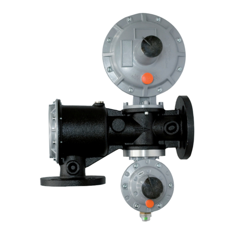
MANUALE TECNICO MT049
Questo manuale si propone di fornire le informazioni
essenziali per l'installazione, la messa in servizio, lo
smontaggio, il rimontaggio e la manutenzione dei rego-
latori Aperflux 851.
Si ritiene comunque opportuno fornire in questa sede
una breve illustrazione delle principali caratteristiche
del regolatore e dei suoi accessori.
1.1 PRINCIPALI CARATTERISTICHE
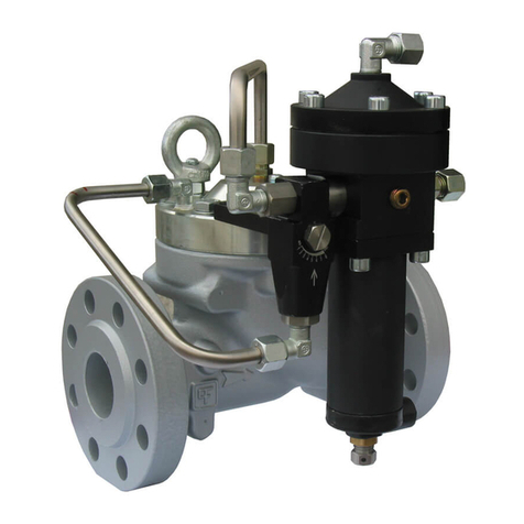
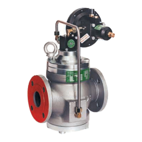
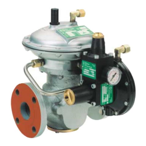
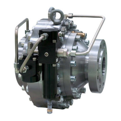
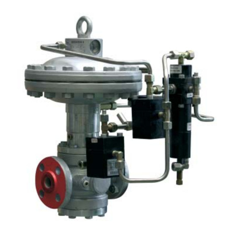
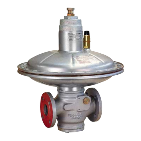
Il regolatore di pressione Aperflux 851 èun regolatore
di tipo pilotato per media e alta pressione.
L'Aperflux 851 èun regolatore a "reazione in apertura"
(fail to open), cioèapre in caso di:
- rottura della membrana principale;
- rottura della/e membrana/e del pilota;
- rottura della pastiglia del pilota;
- mancanza di alimentazione del circuito pilota.
Le caratteristiche principali di questo regolatore sono:
- pressione di progetto: fino a 100 bar;
- temperatura di progetto: -10 °C ÷+50 °C (a richiesta
temperature superiori o inferiori);
- temperatura ambiente: -20 °C ÷+60 °C;
- campo della pressione di entrata bpe: 1 ÷80 bar;
- campo di regolazione possibile Wh: 0,6 ÷65 bar (in
funzione del pilota installato);
- pressione differenziale minima: 0,5 bar;
- classe di precisione RG= fino a 1,5;
- classe di pressione di chiusura SG: fino a 2,5;
1.2 FUNZIONAMENTO (FIG. 1)
La membrana principale 1 in assenza di pressione è
mantenuta in posizione di chiusura dalla molla 2 e pog-
gia sulla sede valvola 3 con griglia 4. La tenuta viene
garantita dal contatto tra la sede valvola 3 e la mem-
brana 1.
In condizioni di normale lavoro sulla membrana 1 agi-
scono le seguenti forze:
- verso il basso: il carico della molla 2, la spinta deri-
vante dalla pressione di controllo Pc nella camera di
controllo A e il peso dell'equipaggio mobile;
- verso l'alto: le spinte derivanti dalla pressione di
monte Pe e di valle Pa e le componenti dinamiche
residue.
La pressione di controllo Pc èottenuta prelevando gas
alla pressione Pe direttamente a monte della membrana
1; il gas viene filtrato dal filtro 6 incorporato nella val-
vola di regolazione del flusso AR73. La pressione Pc
viene governata dal pilota che ne regola il valore. La
This manual proposes to provide the essential informa-
tion for the installation, start-up, disassembly, reas-
sembly and maintenance of the Aperflux 851 regula-
tors.
It is also appropriate, however, to provide a brief il-
lustration of the main features of the regulator and of
its components.
1.1 MAIN FEATURES
The Aperflux 851 pressure regulator is a regulator of
the piloted type for medium and high pressures.
The Aperflux 851 is a "fail to open" type regulator and
therefore opens in the event of:
- rupture of the main diaphragm;
- rupture of the pilot diaphragm/s;
- rupture of the pilot gasket;
- pilot circuit supply failure.
The main features of this regulator are:
- design pressure: up to 100 bar;
- design temperature: -10 °C ÷ +50 °C (higher or lower
temperatures on request);
- environmental temperature: -20 °C ÷ +60 °C;
- range of the inlet pressure bpe: 1 ÷ 80 bar;
- possible regulation range Wh: 0.6 ÷ 65 bar (on the
basis of the pilot installed);
- minimum differential pressure: 0.5 bar;
- precision class RG= up to 1.5;
- closing pressure class SG: up to 2.5.
1.2 OPERATION (FIG. 1)
In the absence of pressure, the main diaphragm 1 is
maintained in the closed position by the spring 2 and
rests on the seat of the valve 3 with grill 4. The seal is
guaranteed by the contact between the valve seat 3 and
the diaphragm 1.
In normal working conditions, the following forces act
on the diaphragm 1:
- downwards: the load of the spring 2, the thrust deri-
ving from the control pressure Pc in the control
chamber A and the weight of the mobile assembly;
- upwards: the thrusts deriving from the upstream
pressure Pe and downstream pressure Pa and the
remaining dynamic components.
The control pressure Pc is obtained by drawing gas at
the pressure Pe directly upstream from the diaphragm
1; the gas is filtered by the filter 6 incorporated in the
AR73 flow regulating valve. The pressure Pc is gover-
ned by the pilot which regulates its value.
TECHNICAL MANUAL MT049
4
1.0 INTRODUZIONE 1.0 INTRODUCTION
