Piktronik KOP2300 User manual

07/2020
KOP2300 Battery charger
User`s manual
48V / 45A


1. Introduction
KOP 3 battery chargers are modern fully automatic devices suitable not only for2 00
charging but also for maintaining and monitoring the batteries. The charger stores
data about charging times and Ah charged. This data may be accessed for further
analysis. The device is protected against reverse polarity and short circuit, has
adjustable time limitations for every charging phase, battery temperature
monitoring and compensation and current reduction at elevated ambient
temperatures.
Your battery charger was programmed for a specific battery type .by your dealer
Make sure the charging profile suits your battery type. To change the charging
profile for a specific battery type, parameters can only be programmed with a PC
software package and a programming interface. The programming parameters
allow the charger's profile to suit the battery type. Up to five charging phases can be
programmed with separate values for charging voltages, currents, charging times,
temperature compensation and other control functions. Please contact your dealer
for further information.
When programming the charging profile always follow the battery manufacturer's
recommendations.
Please read the operating and safety instruction carefully
before using or installing the KOP2300 battery charger!
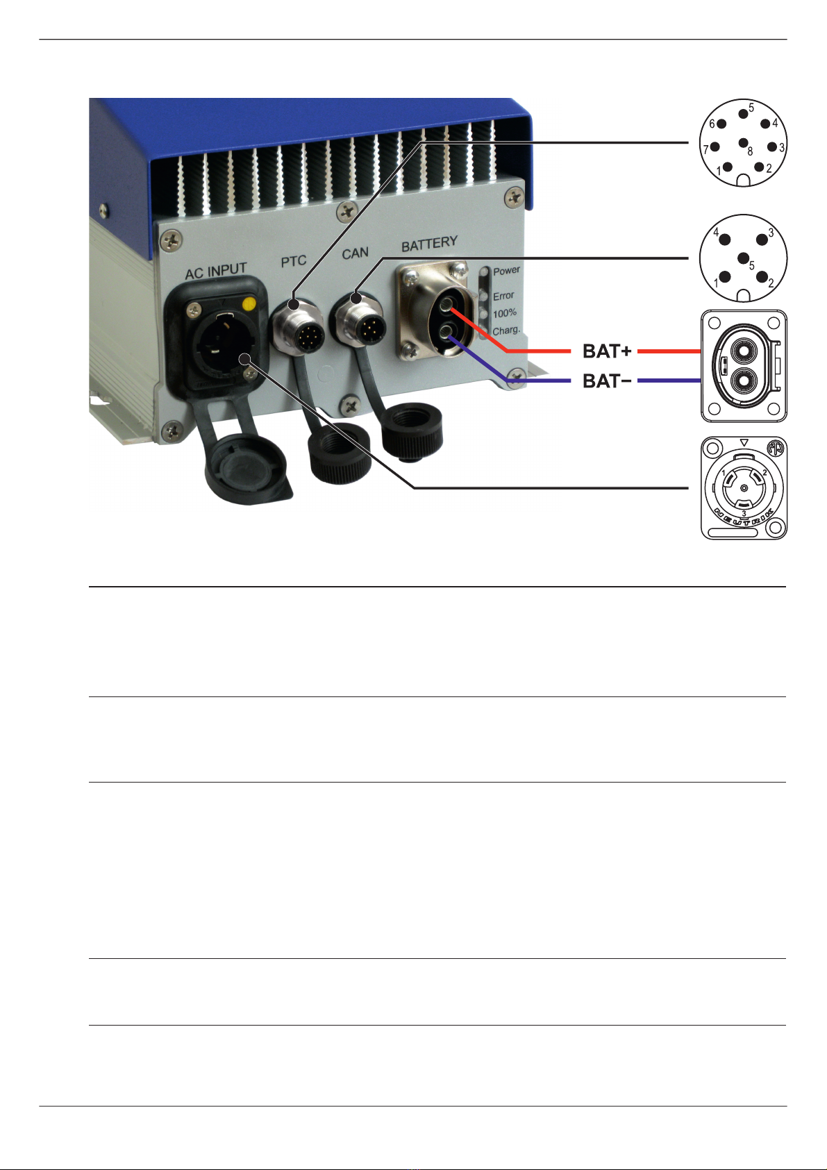
2. Start of the charging process
Establish a safe connection between the battery and the charger first. Then plug the
mains connector. When removing the connection, remove the mains plug from the
mains first, before disconnecting the battery.
The charger type is shown first after the charger has been connected to the mains
and then the measured values as the battery voltage – see the following page.
The charging time depends on battery size and state of charge. If the battery was
only slightly loaded, then the charging process will complete faster. At high ambient
temperatures or when exposed to strong sunlight, the charging current is reduced
and the charging time increased accordingly.
The charger can remain connected to the battery permanently. The current
consumption is less than 0. mA.from the battery 2
10
ENGLISH

3. Mechanical installation
The following things must be considered during the installation:
a. Ensure the distance from the walls or other objects
Ensure the distance from the walls or other objects. Leave enough space (at
least 10cm) between the cooling openings and other objects or walls, so that
the air can circulate well.
b. Avoid the heat build-up
Despite very high efficiency quite a lot of heat arises. Therefore, the charger
must only be installed in places with enough air exchange. Otherwise, the air
temperature rises in the vicinity of the device and the charging current may be
reduced or the device may turn off.
c. Horizontal mounting
Mount the charger on a flat surface as
shown on the image. The device can
withstand higher stress due to vibration
and shock in horizontal position.the
d. Vertical mounting
The cables and terminals must be on the
lower sid as shown on the image.e
IMPORTANT:
The charger be mountedshould not
vertically in applications such as electric
vehicles, since high shock and vibrations
are common in such applications.
IMPORTANT: Observe the additional warnings (see the table). Do not make any
holes on the chassis, as components can be damaged.
Mount the charger on a flat surface.
11
ENGLISH

4. Connections
CAN
AC INPUT
PTC
M12 A-Coding
8 pin
M12 A-Coding
5 pin
Neutrik NAC3MPX
Amphenol PL082X-61-10
NOTE: All contact arrangements shown from the mating side.
Pinout of the CAN connector
1
Shield
2
+12V-CAN
12V power supply (max.100 mA)
3
GND-CAN
Power supply common
4
CAN-H
CAN-High data signal
5
CAN-L
CAN-Low data signal
The signals on the CAN connector are galvanically separated from the battery.
There is no CAN Bus termination resistor in the charger.
Pinout of the PTC connector
1
+12V
12V power supply (max. 150mA)
2
RELAY
Ext. relay (coil between pins 1 and 2)
3
GND-D
Ground connection for +12V and BMS
4
BMS-IN / KOP-USB
5
NC
Not connected
6
PTC
Battery temperature sensor
7
GND-PTC
Ground connection for the PTC
8
+12V
12V power supply
The signals on the PTC connector are not galvanically separated from the battery.
Pinout of the mains (AC INPUT) connector
1
L
Phase
2
PE
Protective earth
3
N
Neutral
12
ENGLISH

5. Functions of the charger software (standard version)
a. Mains current limiter
The mains current, it is limited to max. 13A for 230V systems, and to max. 16A
for 120V systems. KOP2300 automatically detects the mains voltage.
Comment:
For 230V mains voltage and full output power the charger needs approx.
10.5A from the socket. At low mains voltage, the mains current would increase
at the same power, but this would be reduced to max. 13A. In the short term,
the current can also be somewhat higher than 13A in the case of very fast
mains voltage fluctuations.
If the mains voltage drops below approx. 90VAC, the KOP2300 charger is
switched off. After the mains voltage rises again, the charging is restarted
where it was interrupted.
b. CAN Bus
The standard firmware version supports the external display.
For support of special functions, like e.g. communication with the BMS, please
contact Piktronik d.o.o..
c. Relay output
The relay output is switched on when the 230V mains voltage is connected.
Other software options for the relay output on request.
d. Ambient temperature
If the ambient temperature is under -15°C when the charger is connected to
the mains then the start of charging may be delayed by up to 10 minutes. The
LED’s are OFF during this time.
If other functions are required, the charger software can also be updated later via the
CAN connector with theALL-USB programming adapter.
NOTE: The charger has very low power consumption. Therefore, depending on
the function, LED’s on the charger and the external display KOP-DIS1
can remain switched on for more than 5 seconds after the mains plug
has been disconnected.
13
ENGLISH

6. LED functions
Power
100%
Charging
Error
Function
flashing
OFF
OFF
OFF
No firmware loaded or bad firmware version
(bootloader is active).
ON
OFF
OFF
OFF
No battery connected or battery completely
empty.
ON
OFF
flashing
flashing
Battery voltage under the minimal parameter
value. The Charging and Error LED's are
flashing intermittently.
ON
ON
OFF
OFF
Charger waits for the programmed automatic
restart or battery voltage under the minimal
parameter value.
ON
OFF
ON*)
OFF
Charging with full current *)
ON
OFF
flashing*)
OFF
Charging with reduced current –the battery
is almost completely charged *)
ON
OFF
OFF
flashing
Error –see the table in Chapter 8. Number
of consecutive LED flashes defines the error
number.
* This LED functions depend ON the charger parameters –consult your Piktronik
)
dealer.
Charger type
KOP2300
Nominal voltage
48V
Charging current
45A
Minimal starting voltage
23.0V
Adjustable charging voltage range
42.4V to 59,5V
Typ. efficiency at 230 V
96%
Power factor
> 0.95, typ. 0.99 at full power and 230V
Mains voltage
90V - 264V / 47 - 63Hz
Mains current
max. 13A at 230V systems (16A at 120V)
Standby current from the battery
< 0.2mA
Output power
max. 2300W
Dimensions (L x W x H)
407 x 159 x 140 mm
Weight
5.6kg
Environmental protection grade
IP65
Approvals
EN 55022 Class B, EN 60950,
EN 61000-3-2, EN 61000-3-3, EN 61000-4-2,
EN 61000-4-5, EN 61000-4-6, EN 61000-4-11,
EN 61000-6-2, EN 61000-6-3
7. Technical characteristics
14
ENGLISH

8. Error list
Error number and description
1
Charger temperature sensor or cooling fan failed
2
Charging time limit has been exceeded
3
Battery temperature sensor failed or not connected or shorted
4
Internal charger temperature to high
5
Battery voltage too high at the start of the charging
6
Battery temperature too low during charging
7
Battery temperature too high during charging
8
Charger disconnected from the battery during charging
9
Incorrect parameter checksum
10
Bad value from the power module
11
Incorrect parameter values
12
Internal problem with the power module
13
The charging current measurement is outside of the tolerances
14
Internal problem with measurement or voltage regulation
Please provide that error number when the supplier or manufacturer is contacted.
9. Troubleshooting
Issue
Remedy
LED’s on the device do not
turn on after connection to the
mains socket
Check the mains connection.
Check if the mains voltage is present.
Charging does not start
Check the battery connection, battery voltage,
fuses and connection to the BMS.
Battery voltage is too low
The battery voltage is lower than the minimum
value at which the charger is allowed to start.
15
ENGLISH

10. General information
uRead the manual thoroughly.
uThe charger must be used with the original cables only. Do not change, shorten,
extend or short circuit the cables.
uRemove the mains plug from the mains socket first before breaking the battery
connection.
uOnly rechargeable batteries can be used. Do not connect any non- rechargeable
batteries (like dry-cell batteries) to the charger.
uThe charger must be used for the correct battery type only.
uDo not install the charger inside motor-homes, campers or caravans.
uCheck the charger for cable, housing and connector damages before use. Do
not operate the charger when damaged.
uThere are no user serviceable parts inside. Refer servicing to qualified service
personnel.
uDo not expose the charger to rain, moisture, direct sunlight or dust.
uAlways disconnect the mains after charging and generally when the device is not
in use. During the trickle charge the charger remains attached to the mains.
uObserve the warnings on the last page of this manual.
16
ENGLISH

11. Warnings
COOLING
Do not cover the charger housing and protect it from direct sunlight
or other heat sources. The charging current is reduced at elevated
ambient temperatures and the charging time increases
accordingly. he built-in fan must be able to cool the electronicsT
well.
CONNECTION
Output currents are very high. Select the correct wire/cable size,
use ferrules for wire ends, keep contact points clean and properly
connect the output terminals.
FUSES
The fuse in the charger is not a sufficient protection for the battery
cable from the battery to the charger. A corresponding fuse must
be located in the immediate vicinity of the battery terminal.
MAINS
CONNECTION
The line current is limited by the charger firmware - please see
technical data. Please check if the wall socket and the mains fuse
meet this current.
BATTERY
TYPE / SIZE
Use this charger for the pre-set battery type and size only,
otherwise the battery may not be fully charged or the battery can
be damaged or it's life can be reduced.time
LITHIUM
BATTERIES
Lithium batteries are very sensitive to overcharging and
overheating. The charger can regulate only the total voltage, but
can not recognize states of individual cells. Therefore, the charger
should only be used together with a battery management system.
LEAD-ACID
BATTERY
GASSES
Lead-acid batteries produce hydrogen-oxygen gases, which can
be explosive, and sulfuric acid that can cause severe burns. Make
sure the working area is well-ventilated. Cigarettes or any open
fires or sparks may cause an explosion. Keep all ignition sources
away from the battery.
ACIDS
Battery acid can damage your eyes and skin. In the event of an
accident, flush with water and seek medical help immediately. Use
proper personal protective devices when handling a damaged or
leaking battery. Treat the material used to clean up the battery acid
spill as hazardous waste.
TOXIC
SUBSTANCES
Batteries contain hazardous materials. Among others, lead and
antimony are toxic substances. Waste lead-acid and many other
battery types are hazardous waste and must be treated according
to the Battery Disposal Regulations.
17
ENGLISH


www.piktronik.com
A solutions for b owereddvanced attery p vehicles and boats
Adresse/
Address:
Piktronik d.o.o.
Cesta k Tamu 17
SI-2000 Maribor
Slowenien
Tel.:
+386-2-460-2250
Fax:
+386-2-460-2255
Internet:
www.piktronik.com
E-mail:
07/2020
Table of contents
Other Piktronik Batteries Charger manuals
Popular Batteries Charger manuals by other brands

Aeca
Aeca Xtender XTH 3000-12 Installation and operating instructions

Circutor
Circutor URBAN installation guide

HindlePower
HindlePower AT10.1 series Operating instruction

Yokomo
Yokomo YZ-114 Plus instruction manual

Tryton
Tryton TJ3LD Operating instruction

Analytic Systems
Analytic Systems BCA310-110-48 Installation & operation manual