6. Functions of the charger software (standard version)
a. Mains current limiter
Most sockets are protected between 10 A and 16 A on the mains side. Very few
sockets tolerate a continuous current of more than 15 A. To avoid overheating with
excessive mains current, it is limited to max. 14.7 A (see the description below for
further current limit selection with the BMS input).
Comment:
For 230 V mains voltage and full output power the charger needs approx. 14.2 A from
the socket. At low mains voltage, the mains current would increase at the same
power, but this would be reduced to max. 14.7 A. In the short term, the current can
also be somewhat higher than 14.7 A in the case of very fast mains voltage
fluctuations. If the mains voltage drops below approx. 180 Vac, the KOP3 charger is
switched off. After the mains voltage rises again, the charging is restarted where it
was interrupted.
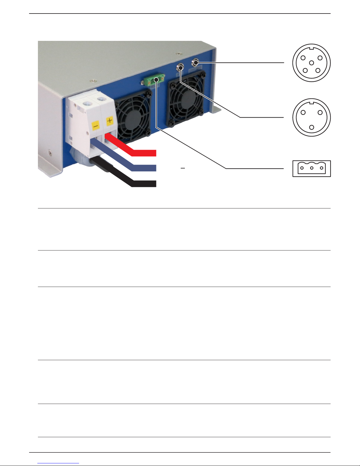
b. BMS input
The selection of the mains current limitation is the standard function of this input. If
this input is connected to ground (GND), the mains current is limited to 8.7 A, if not,
then the mains current is limited to 14.7 A. Other values on request. A plug with the
preassembled switch can be ordered as an option.
Special software versions are to be ordered if the BMS input is used for
communication with the battery management system. Contact Piktronik for the
description of the BMS PWM interface.
c. CAN Bus
The standard firmware version supports the external display. For support of special
functions, like E.g. communication with the BMS, please contact Piktronik.
d. Relay output
This is switched on when 230 V is connected. Other software options for relay output
on request.
If other functions are required, the charger software can also be changed later via the
PTC connector with the KOP-USB programming adapter.
7
NOTE: The charger has very low power consumption. Therefore, depending on the
function, the display can remain switched on for more than 20 seconds after the
mains plug has been disconnected.