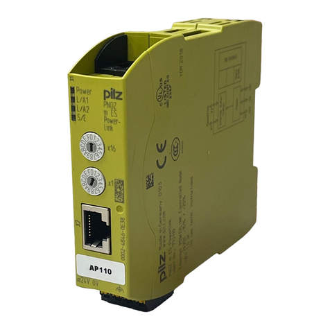
Pilz PNOZ mc4p User manual

Erweiterungsmodul PNOZ mc4p
DeviceNet
Das Erweiterungsmodul PNOZ mc4p darf nur
an ein Basisgerät (z. B. PNOZ m1p des
modularen Sicherheitssystems PNOZmulti)
angeschlossen werden. Es koppelt das
modulare Sicherheitssystem PNOZmulti an
DeviceNet. Das modulare Sicherheitssystem
PNOZmulti dient dem sicherheitsgerichteten
Unterbrechen von Sicherheitsstromkreisen
und ist bestimmt für den Einsatz in:
• NOT-AUS-Einrichtungen
• Sicherheitsstromkreisen nach VDE 0113
Teil 1, 11/98 und EN 60204-1, 12/97
(z. B. bei beweglichen Verdeckungen)
Achtung! Das Erweiterungsmodul
PNOZ mc4p darf nicht für
sicherheitsgerichtete Funktionen
verwendet werden.
Zu Ihrer Sicherheit
Beachten Sie nachfolgend aufgeführte
Sicherheitsbestimmungen:
• Installieren und nehmen Sie das Modul nur
dann in Betrieb, wenn Sie mit dieser
Betriebsanleitung und den geltenden
Vorschriften über Arbeitssicherheit und
Unfallverhütung vertraut sind.
• Verwenden Sie das Modul nur gemäß
seiner Bestimmung. Beachten Sie dazu
auch die Werte im Abschnitt "Technische
Daten".
• Halten Sie beim Transport, bei der
Lagerung und im Betrieb die Bedingungen
nach EN 60068-2-6, 04/95 ein (siehe
"Technische Daten").
• Öffnen Sie nicht das Gehäuse und
nehmen Sie auch keine eigenmächtigen
Umbauten vor.
• Schalten Sie bei Wartungsarbeiten
unbedingt die Versorgungsspannung ab.
Beachten Sie unbedingt die Warnhinweise in
den anderen Abschnitten dieser Anleitung.
Diese Hinweise sind optisch durch Symbole
hervorgehoben.
Wichtig: Beachten Sie die Sicher-
heitsbestimmungen, sonst erlischt
jegliche Gewährleistung.
Modulbeschreibung
DeviceNet ist konzipiert für den schnellen
Datenaustausch in der Feldebene. Das
Erweiterungsmodul PNOZ mc4p ist ein
passiver Teilnehmer (Slave) des DeviceNet.
Die Grundfunktionen der Kommunikation
entsprechen DeviceNet 2.0. Die zentrale
Steuerung (Master) liest zyklisch die
Eingangsinformationen von den Slaves und
schreibt die Ausgangsinformationen zyklisch
an die Slaves. Neben der zyklischen
Nutzdatenübertragung verfügt das PNOZ
mc4p auch über Funktionen für Diagnose
und Inbetriebnahme.
PNOZ mc4p DeviceNet expansion
module
The PNOZ mc4p expansion module may
only be connected to a base unit (e.g.
PNOZ m1p from the PNOZmulti modular
safety system). It connects the PNOZmulti
modular safety system to DeviceNet. The
PNOZmulti modular safety system is used for
the safety-related interruption of safety
circuits and is designed for use in:
• Emergency stop equipment
• Safety circuits in accordance with
VDE 0113 Part 1, 11/98 and EN 60204-1,
12/97 (e.g. on movable guards)
Caution! The PNOZ mc4p expan-
sion module may not be used for
safety-related functions.
For your safety
Please note the following safety regulations:
• Only install and commission the module if
you are familiar with both these instruc-
tions and the current regulations for health
and safety at work and accident preven-
tion.
• Only use the module in accordance with its
intended purpose. Please also take note of
the values in the “Technical details”
section.
• Transport, storage and operating condi-
tions should all conform to EN 60068-2-6,
04/95 (see “Technical details”).
• Do not open the housing or undertake any
unauthorised modifications.
• Always switch off the supply voltage when
carrying out maintenance work.
You must take note of the warnings given in
other sections of these operating instruc-
tions. These are highlighted visually through
the use of symbols.
Notice: Failure to keep to these safety
regulations will render the warranty
invalid.
Module description
The DeviceNet is designed for fast data
exchange at the field level. The PNOZ mc4p
expansion module is a passive
DeviceNet
subscriber (slave). The basic functions of
communication correspond to DeviceNet 2.0.
The central controller (master) reads input
information from the slaves and writes output
information to the slaves as part of each
cycle. As well as the cyclical transfer of
usable data, PNOZ mc4p can also be used
for diagnostics and commissioning functions.
PNOZmc4pDeviceNetPNOZmc4pDeviceNet
PNOZmc4pDeviceNet増設モジュール増設モジュール
増設モジュール増設モジュール
増設モジュール
PNOZmc4p増設モジュールは、ベースユ
ニット(例:PNOZmultiモジュラー安全コン
トローラのPNOZm1p)にのみ接続できま
す。本製品はPNOZmultiモジュラー安全コ
ントローラをDeviceNetに接続します。
PNOZmultiモジュラー安全コントローラ
は、安全回路を遮断するために使用しま
す。本製品は以下でご使用いただけます。
•非常停止装置
•VDE0113Part1,11/98および
EN60204‑1,12/97対応の安全回路
(例:可動ガード)
注意!注意!
注意!注意!
注意!PNOZmc4p増設モジュール
は、、
、、
、安全関連機能にはご使用になれなれ
なれなれ
なれ
ません。ません。
ません。ません。
ません。
安全なご使用のために安全なご使用のために
安全なご使用のために
以下の安全上の注意事項に従ってください
•使用上の注意、作業時の安全衛生や事故
防止に関連した現行法規をご理解の上、
取付け、運転をしてください。
•本製品の本来の使用目的に沿ってご使用
ください。また、"技術データ欄の各数
値にも留意してください。
•運送、保管、動作条件はすべてEN60068‑
2‑6,04/95に従ってください(技術デー
タ参照)。
•ハウジングを開けたり、無断で製品の改
造をしたりしないでください。
•保守作業保守作業
保守作業保守作業
保守作業を行う際には、必ず供給電圧を
切ってください。
本書の他のセクションにある警告にも留意
してください。警告はわかりやすいように
マークで表示しています。
注意注意
注意注意
注意:上記の安全上の注意事項に従
わなかった場合、製品保証は無効とな
ります。
製品詳細製品詳細
製品詳細製品詳細
製品詳細
DeviceNetは、フィールドレベルでの高速
データ交換用に設計されています。
PNOZmc4p増設モジュールは、パッシブ
DeviceNet子局(スレーブ)です。通信の
基本機能は、DeviceNet2.0に対応していま
す。中央コントローラ(マスター)はス
レーブからの入力情報を読込み、各サイク
ルの一部として出力情報をスレーブに書込
みます。使用可能データの周期的な転送の
他、PNOZmc4pは故障診断や試運転機能とし
てもご利用いただけます。
21 054J-01
PNOZ mc4p
D Betriebsanleitung
GB Operating instructions
日 取扱説明書

Innenschaltbild
PNOZ m1p
Controller
NSMS
DR S1
S2
32
16
8
4
2
1
NA
DeviceNet
V-
CL
V
CH
1
2
3
4
5
SD
Internalwiring
diagram 内部配線図
Modulmerkmale:
• konfigurierbar mit PNOZmulti Configurator
• Stationsadressen wählbar von 0 ... 63 mit
DIP-Schalter
• Statusanzeigen für Kommunikation mit
DeviceNet
und von Fehlern
Funktionsbeschreibung
Arbeitsweise:
Die über DeviceNet zu übertragenden Daten
werden im PNOZmulti Configurator ausge-
wählt und konfiguriert.
Die Verbindung zwischen Basisgerät und
dem PNOZ mc4p erfolgt über eine Steck-
brücke. Über diese Steckbrücke wird das
PNOZ mc4p auch mit Spannung versorgt.
Die Stationsadresse und die Übertragungs-
rate werden mit DIP-Schaltern eingestellt.
Nach Einschalten der Versorgungsspannung
oder einem Reset des Sicherheitssystems
PNOZmulti wird das PNOZ mc4p automa-
tisch konfiguriert und gestartet.
Funktionen:
LEDs zeigen den Status des Erweiterungs-
moduls PNOZ mc4p am DeviceNet an.
INFO
In der Online-Hilfe des PNOZmulti
Configurators ist die Konfiguration
des PNOZ mc4p ausführlich beschrie-
ben.
PNOZ mc4p montieren
Basisgerät und PNOZ mc4p verbinden
Beachten sie vor der Montage des PNOZ
mc4p die folgenden Sicherheitshinweise:
Achtung! Durch elektrostatische
Entladung können Bauteile des
Erweiterungsmoduls beschädigt
werden. Sorgen Sie für Entladung,
bevor Sie das Erweiterungsmodul
berühren, z. B. durch Berühren einer
geerdeten, leitfähigen Fläche oder
durch Tragen eines geerdeten
Armbands.
Achtung! Montieren Sie das
Sicherheitssystem PNOZmulti in
einen Schaltschrank mit einer
Schutzart von mindestens IP54.
Achtung! Montieren Sie das
Sicherheitssystem auf eine waag-
rechte Tragschiene. Andere
Einbaulagen können zur Zerstörung
des Sicherheitssystems führen.
Module features:
•
Can be configured using the PNOZmulti Configurator
• Available station address range from 0 -
63 using DIP switches
• Status indicators for communication with
DeviceNet
and for errors
Function description
Operation:
The data to be transferred via
DeviceNet are
selected and configured in the PNOZmulti
Configurator.
The base unit and the PNOZ mc4p are
connected via a jumper. The PNOZ mc4p is
also supplied with voltage via this jumper.
The station address and the transmission
rate are set using DIP switches. After the
supply voltage is switched on or the
PNOZmulti safety system is reset, the PNOZ
mc4p is configured and started automatically.
Functions:
LEDs indicate the status of the PNOZ mc4p
expansion module on DeviceNet.
INFORMATION
The configuration of the PNOZ mc4p
is described in detail in the
PNOZmulti Configurator’s online help.
Installing the PNOZ mc4p
Connect the base unit and PNOZ mc4p
Before installing the PNOZ mc4p, please
note the following safety guidelines:
Caution! Electrostatic discharge can
damage components on the
expansion module. Ensure against
discharge before touching the
expansion module, e.g. by touching
an earthed, conductive surface or by
wearing an earthed armband.
Caution! The PNOZmulti safety
system should be installed in a
control cabinet with a protection type
of at least IP54.
Caution! Fit the safety system to a
horizontal DIN rail. Other mounting
positions could damage the safety
system.
モジュールの特徴モジュールの特徴
モジュールの特徴モジュールの特徴
モジュールの特徴::
::
:
•PNOZmultiConfiguratorでコンフィグ
レーション可能
•0...63までのステーションアドレスを
DIPスイッチで選択
•DeviceNetとの通信およびエラーの状態
表示
機能の特徴機能の特徴
機能の特徴機能の特徴
機能の特徴::
::
:
動作:動作:
動作:動作:
動作:
DeviceNetで転送するデータは、PNOZmulti
Configuratorで選択され、コンフィグレー
ションされます。
ベースユニットとPNOZmc4pは増設コネク
タで接続されます。PNOZmc4pは、この増設
コネクタから電源も供給されます。ステー
ションアドレスと伝送速度は、DIPスイッチ
で設定されます。供給電源投入後、または
PNOZmulti安全コントローラがリセットされ
ると、PNOZmc4pは自動的にコンフィグ
レーションされ、起動します。
機能機能
機能機能
機能::
::
:
LEDはPNOZmc4p増設モジュールの
DiviceNet上の状態を表示します。
インフォメーションインフォメーション
インフォメーションインフォメーション
インフォメーション
PNOZmc4pのコンフィグレーション
については、PNOZmulti
Configuratorのオンラインヘルプに
詳しい説明があります。
PNOZmc4pPNOZmc4p
PNOZmc4pPNOZmc4p
PNOZmc4pの取り付けの取り付け
の取り付けの取り付け
の取り付け
ベースユニットとベースユニットと
ベースユニットとベースユニットと
ベースユニットとPNOZmc4pPNOZmc4p
PNOZmc4pPNOZmc4p
PNOZmc4pの接続の接続
の接続の接続
の接続
PNOZmc4pを取り付ける前に、以下の安全
ガイドラインに注意してください:
注意注意
注意注意
注意!!
!!
!静電放電によって増設モ
ジュールの部品が損傷する場合があ
ります。増設モジュールに触れる前
に、接地伝導面に触れるまたは、接
地アームバンドを装着するなどし
て、放電を必ず防いでください。
注意注意
注意注意
注意!!
!!
!PNOZmulti安全コントロー
ラは、IP54以上の保護構造の制御盤
に取り付けなければなりません。
注意注意
注意注意
注意!!
!!
!安全コントローラをDIN
レールに水平に取り付けてくださ
い。他の取り付けでは、安全コント
ローラが損傷するおそれがありま
す。

• Die Module werden mit Steckbrücken
verbunden. Auf der Geräterückseite des
Basisgeräts PNOZ m1p befinden sich
2 Stiftleisten. An der rechten Stiftleiste
befindet sich ein Abschlussstecker.
•Montieren Sie das Erweiterungsmodul
PNOZ mc4p links vom Basisgerät mit
der mitgelieferten Steckbrücke.
• Befestigen Sie das PNOZ mc4p mit Hilfe
der Rastelemente auf der Rückseite auf
einer Normschiene. Führen Sie das PNOZ
mc4p gerade auf die Normschiene, so
dass die Erdungsfedern am PNOZ mc4p
auf die Normschiene gedrückt werden.
• Um die EMV-Anforderungen einzuhalten,
muss die Normschiene mit dem Schalt-
schrankgehäuse niederohmig verbunden
sein.
• Zwischen dem PNOZ mc4p und externen
Wärmequellen muss mind. 20 mm
Abstand eingehalten werden.
PNOZ mc4p inbetriebnehmen
Inbetriebnahme vorbereiten:
Beachten Sie bei der Vorbereitung der
Inbetriebnahme:
Achtung! Das Erweiterungsmodul
PNOZ mc4p nur im spannungslo-
sen Zustand ziehen und stecken.
Wichtig: Beachten Sie bei der
Installation unbedingt die Anforderun-
gen der DeviceNet Specification,
Volume I, Release 2.0.
Betriebsbereitschaft herstellen:
•Übertragungsrate einstellen
Stellen Sie mit den DIP-Schaltern S1 und
S2 (DR) die Übertragungsrate ein.
• The modules are linked via jumpers. There
are 2 pin connectors on the rear of the
PNOZ m1p base unit. The right-hand pin
connector contains a terminating plug.
•Install the PNOZ mc4p expansion module
to the left of the base unit using the
jumper supplied.
• Use the notches on the back of the
PNOZ mc4p to attach it to a DIN rail.
Connect the PNOZ mc4p to the DIN rail in
an upright position so that the earthing
springs on the PNOZ mc4p are pressed on
to the DIN rail.
• To comply with EMC requirements, the
DIN rail must have a low impedance
connection to the control cabinet housing.
• A minimum distance of 20 mm must be
maintained between the PNOZ mc4p and
external heat sources.
Commissioning the PNOZ mc4p
Preparing for commissioning:
Please note the following when preparing to
commission the unit:
Caution! Only connect and disconnect
the PNOZ mc4p expansion module when
the supply voltage is switched off.
Important: Be sure to observe the
requirements of the DeviceNet
specification, volume I, release 2.0
during installation.
Preparing the unit for operation:
•Set transmission rate
Set the transmission rate using DIP
switches S1 and S2 (DR).
•モジュールは増設コネクタで接続されて
います。PNOZm1pベースユニットの背面
には、2つのpinコネクタがあります。
右手のpinコネクタには終端コネクタが
接続されます。
•PNOZmc4p増設モジュールを付属の増設
コネクタを使ってベースユニットの左側ベースユニットの左側
ベースユニットの左側ベースユニットの左側
ベースユニットの左側
にに
にに
に取り付けてください。
•PNOZmc4pの裏側のノッチを使ってDIN
レールに取り付けます。PNOZmc4pの接
地スプリングがDINレールを押さえるよ
うに、PNOZmc4pをDINレールに垂直に
取り付けてください。
•EMC要求事項に適応するため、DINレー
ルは制御盤の本体に低いインピーダンス
で接続しなければなりません。
•PNOZmc4pと外部の熱源との距離を最小
20mm確保しなければなりません。
PNOZmc4pPNOZmc4p
PNOZmc4pPNOZmc4p
PNOZmc4pの運転の運転
の運転の運転
の運転
運転の準備運転の準備
運転の準備運転の準備
運転の準備::
::
:
ユニットの運転を準備する際には、以下の
点に注意してください:
注意注意
注意注意
注意!!
!!
!PNOZmc4p増設モジュール
を接続したり取り外したりする際に
は、必ず供給電源を切ってください必ず供給電源を切ってください
必ず供給電源を切ってください必ず供給電源を切ってください
必ず供給電源を切ってください
重要重要
重要重要
重要::
::
:取り付けの際は、DeviceNet
仕様書,volumeI,version2.0の
要求事項に必ず従ってください。
ユニットの運転準備ユニットの運転準備
ユニットの運転準備ユニットの運転準備
ユニットの運転準備::
::
:
•伝送速度の設定伝送速度の設定
伝送速度の設定伝送速度の設定
伝送速度の設定
DIPスイッチS1およびS2を使って伝送
速度を設定してください(DR)。
PNOZmc4pmontieren
InstallthePNOZmc4ptotheleftofInstallthePNOZmc4ptotheleftof
InstallthePNOZmc4ptotheleftof
thebaseunit!thebaseunit!
thebaseunit! PNOZmc4pPNOZmc4p
PNOZmc4pPNOZmc4p
PNOZmc4pをベースユニットの左側にをベースユニットの左側に
をベースユニットの左側にをベースユニットの左側に
をベースユニットの左側に
取り付けてください取り付けてください
取り付けてください取り付けてください
取り付けてください!!
!!
!
InstallingthePNOZmc4p PNOZmc4pの取り付け
Basisgerät/
Base unit/
Appareil de base
Erweiterungsmodul 1/
Expander module 1/
Module d'extension 1
Erweiterungsmodul 8/
Expander module 8/
Module d'extension 8
774 640: Steckbrücke/Link/
Cavalier de pontage
779 110: Abschlussstecker/Terminator/
Fiche de terminaison
PNOZ mc4p
DeviceNet
INFOWährend des Betriebs kann die
Übertragungsrate nicht verändert
werden.
INFORMATION
The transmission rate cannot be
changed during operation.
インフォメーションインフォメーション
インフォメーションインフォメーション
インフォメーション
運転中は、伝送速度の変更はできませ
ん。
Übertragungsrate/Transmission rate/ 伝送速度
125 kBit/s
250 kBit/s
500 kBit/s
‑‑‑
S2
Aus/Off/ オフ
Aus/Off/ オフ
Ein/On/オン
Ein/On/オン
S1
Aus/Off/ オフ
Ein/On/オン
Aus/Off/ オフ
Ein/On/オン
DIP-Schalter/DIP switches/ DIPスイッチ

•Stationsadresse einstellen
Die Stationsadresse des PNOZ mc4p wird
mit DIP-Schaltern 1bis 32 von 0 ... 63
(binär) eingestellt.
Ausgangsdaten
Die Ausgangsdaten sind wie folgt aufgebaut:
• Byte 0 bis 2 (24 Ausgänge):
konfigurierbar im PNOZmulti Configurator
mit Ausgängen von Logikelementen,
Zeitgliedern, Ereigniszählern, Anschluss-
punkten oder Eingängen des PNOZmulti.
Die Zuordnung der Ausgänge im
PNOZmulti Configurator zu den
DeviceNet-Ausgangsdaten entnehmen Sie
der Tabelle im folgenden Abschnitt.
• Byte 3:
Bit 0 ... 4: LED-Zustände des PNOZmulti
- Bit 0: OFAULT
- Bit 1: IFAULT
- Bit 2: FAULT
- Bit 3: DIAG
- Bit 4: RUN
Bit 5: Datenaustausch findet statt
•Setting the station address
The station address of the PNOZ mc4p is
set from 0 - 63 (binary) using DIP switches
1to 32.
Output data
The output data are structured as follows:
• Byte 0 to 2 (24 outputs):
Can be configured in the PNOZmulti Configurator
with outputs from logic elements, time
elements, event counters, connection points
or inputs on the PNOZmulti. The allocation
of outputs in the PNOZmulti Configurator to
the
DeviceNet
output data can be found in
the table in the following section.
• Byte 3:
Bit 0 ... 4: Status of LEDs on the PNOZmulti
- Bit 0: OFAULT
- Bit 1: IFAULT
- Bit 2: FAULT
- Bit 3: DIAG
- Bit 4: RUN
Bit 5: Data are being exchanged
•ステーションアドレスの設定ステーションアドレスの設定
ステーションアドレスの設定ステーションアドレスの設定
ステーションアドレスの設定
PNOZmc4pのステーションアドレスは、
DIPスイッチ1‑321‑32
1‑321‑32
1‑32を使って、0...63(バ
イナリ)に設定します。
出力データ出力データ
出力データ出力データ
出力データ
出力データは以下のよう構成です:
•
Byte0から2(24出力):
PNOZmultiConfiguratorでロジックファ
ンクション、クロック、イベントカウン
ター、内部フラグ、またはPNOZmultiの入
力によってコンフィグレーションできま
す。DeviceNet出力データへのPNOZmulti
Configuratorの出力割付けは、以下の
項のテーブルでご覧いただけます。
•
Byte3:
Bit0...4:PNOZmultiのLEDの状態
‑ Bit0:OFAULT
‑ Bit1:IFAULT
‑ Bit2:FAULT
‑ Bit3:DIAG
‑ Bit4:RUN
Bit5:データ交換中です
4
Aus/Off/オフ
Aus/Off/オフ
Aus/Off/オフ
Aus/Off/オフ
...
Ein/On/オン
Ein/On/オン
Stationsadresse/Stationaddress/
ステーションアドレス
0
1
2
3
...
62
63
16
AAus/Off/オフ
Aus/Off/オフ
Aus/Off/オフ
Aus/Off/オフ
...
Ein/On/オン
Ein/On/オン
32
Aus/Off/オフ
Aus/Off/オフ
Aus/Off/オフ
Aus/Off/オフ
...
Ein/On/オン
Ein/On/オン
DIP‑Schalter/DIPswitches/DIPスイッチ
8
Aus/Off/オフ
Aus/Off/オフ
Aus/Off/オフ
Aus/Off/オフ
...
Ein/On/オン
Ein/On/オン
2
Aus/Off/オフ
Aus/Off/オフ
Ein/On/オン
Ein/On/オン
...
Ein/On/オン
Ein/On/オン
1
Aus/Off/オフ
Ein/On/オン
Aus/Off/オフ
Ein/On/オン
...
Aus/Off/オフ
Ein/On/オン
• Legen Sie die Versorgungspannung an
das Basisgerät:
Klemmen 24 V und A1 (+): + 24 V DC
Klemmen 0 V und A2 (-): 0 V
Betrieb
Nach Einschalten der Versorgungsspannung oder einem
Reset des Sicherheitssystems PNOZmulti wird das PNOZ
mc4p automatisch konfiguriert und gestartet. Die LEDS
"MS" und "NS" zeigen den Status des PNOZ mc4p am
DeviceNet an.
LED-Anzeige
LED aus
LED leuchtet
LED blinkt
• Connect the supply voltage to the base
unit:
Terminals 24 V and A1 (+): + 24 V DC
Terminals 0 V and A2 (-): 0 V
Operation
After the supply voltage is switched on or the
PNOZmulti safety system is reset, the
PNOZ mc4p is configured and started
automatically. The "MS" and "NS" LEDs
indicate the status of the PNOZ mc4p on the
DeviceNet.
LEDs
LED off
LED on
LED flashes
•供給電源をベースユニットに接続してく
ださい:
24V24V
24V24V
24VおよびA1(+)A1(+)
A1(+)A1(+)
A1(+)端子端子
端子端子
端子:+24VDC
0V0V
0V0V
0VおよびA2(‑)A2(‑)
A2(‑)A2(‑)
A2(‑)端子端子
端子端子
端子:0V
動作動作
動作動作
動作
供給電源投入後、またはPNOZmulti安全コ
ントローラがリセットされた後、PNOZmc4p
は自動的にコンフィグレーションされ、起
動します。"MSMS
MSMS
MS"と"NSNS
NSNS
NS"のLEDが、PNOZ
mc4pのDeviceNetでの状態を表示します。
LEDLED
LEDLED
LED表示表示
表示表示
表示
LED消灯
LED点灯
LED点滅
LED-Zustand
LED status
LED
の状態
grün/green/緑
grün/green/緑
rot/red/赤
rot/red/赤
grün/green/緑
緑
赤
赤
Bedeutung
Meaning
Keine Versorgungsspannung oder
Offline
PNOZ mc4p im Betriebszustand
"Link OK, Online, Connected"
PNOZ mc4p im Betriebszustand
"Online, Not connected"
PNOZ mc4p erkennt "Critical link
failure"
Zeitüberwachung (“Connection
Timeout”) ist abgelaufen.
Keine Versorgungsspannung am
PNOZ mc4p
PNOZ mc4p im Betriebszustand
"Device Operational"
Konfigurationsfehler, Größe der
Daten entsprechen nicht der
Konfiguration
PNOZ mc4p erkennt nicht
behebbaren Fehler
PNOZ mc4p erkennt behebbaren
Fehler ("Minor Fault")
LED
NS
MS
Key
No supply voltage or
offline
PNOZ mc4p in "Link OK, Online,
Connected" operating status
PNOZ mc4p in "Online,
Not connected" operating status
PNOZ mc4p recognises "Critical link
failure".
Time monitoring ("Connection
Timeout") has expired.
No supply voltage at the
PNOZ mc4p.
PNOZ mc4p in "Device Operational"
operating status
Configuration fault; size of data
does not correspond to the
configuration
PNOZ mc4p recognises non-
recoverable fault
PNOZ mc4p recognises
recoverable fault ("Minor Fault")
説明
電源が供給されていないか"オフライ
ン"です
PNOZmc4pは:"リンクOK,オンライ
ン,接続中"の状態です
PNOZmc4pは:"オンライン、未接続"
の状態です
PNOZmc4pが"リンクの重大エラー"を
認識しました
監視時間("接続タイムアウト")が切
れました。
PNOZmc4pに電源が供給されていませ
ん
PNOZmc4pは:"装置運転可能"の状態
です
コンフィグレーションエラー、デー
タのサイズがコンフィグレーションに
対応しません
PNOZmc4pは修復不能なエラーを認識
しました
PNOZmc4pは修復可能なエラーを認識
しました("マイナーエラー")

Zuordnung der Ausgänge im PNOZmulti
Configurator zu den DeviceNet-
Ausgangsdaten
Allocation of outputs in the
PNOZmulti Configurator to the DeviceNet
output data
DeviceNet interface
The PNOZ mc4p has a 5-pin screw
connector for connecting to the DeviceNet.
Information on configuring the interface is
found on the second to last page.
The last two pages contain a connection
example, the pin configuration, the configura-
tion of the DeviceNet interface and the unit’s
dimensions.
DeviceNetDeviceNet
DeviceNetDeviceNet
DeviceNet出力データへの出力データへの
出力データへの出力データへの
出力データへのPNOZmultiPNOZmulti
PNOZmultiPNOZmulti
PNOZmulti
ConfiguratorConfigurator
Configurator出力割付出力割付
出力割付出力割付
出力割付
O0 ... O7
Byte/Octet 0 :
Bit 0 ... 7
O8 ... O15
Byte/Octet 1 :
Bit 0 ... 7
O16 ... O23
Byte/Octet 2 :
Bit 0 ... 7
Ausgänge PNOZmulti Configurator/Outputs on PNOZmulti Configurator/
PNOZmultiConfigurator出力
Ausgangsdaten DeviceNet/DeviceNet output data/ DeviceNet出力データ
Technical details
Electrical data
Supply voltage (UB) via base unit
Power consumption at UB
Times
Supply interruption before de-
energisation
DeviceNet
Supply voltage V+, V-
via bus cable
Power consumption
Application range
Device type
Status display
Station address
Transmission rate
Connection
Galvanic isolation
Test voltage
Environmental data
Climatic suitability
EMC
Vibration to
Frequency
Amplitude
Ambient temperature
Storage temperature
Mechanical data
Protection type
Mounting (e.g. control cabinet)
Housing
Terminals
Housing material
Front panel
Housing
Dimensions H x W x D
Weight
技術データ技術データ
技術データ技術データ
技術データ
電気的データ
供給電圧(UB)
消費電力
時間
電源瞬断許容時間
DeviceNetDeviceNet
DeviceNetDeviceNet
DeviceNet
供給電圧V+,V‑
バスケーブル経由
消費電力
アプリケーション範囲
デバイスタイプ
状態表示
ステーションアドレス
伝送速度
接続
ガルバニック絶縁
試験電圧
環境条件データ
周囲環境条件
EMC
耐振動
周波数
振幅
使用許容周囲温度
保管温度
機械的データ
保護構造
マウンティング部(例:制御盤)
ハウジング部
端子
ケース素材
フロントパネル
ハウジング
寸法HxWxD
重量
Technische Daten
Elektrische Daten
Versorgungsspannung (UB) über
Basisgerät
Leistungsaufnahme bei UB
Zeiten
Überbrückung von
Spannungseinbrüchen
DeviceNet
Versorgungsspannung V+, V-
über Buskabel
Leistungsaufnahme
Anwendungsbereich
Gerätetyp
Statusanzeige
Stationsadresse
Übertragungsrate
Anschluss
Galvanische Trennung
Prüfspannung
Umweltdaten
Klimabeanspruchung
EMV
Schwingungen nach
Frequenz
Amplitude
Umgebungstemperatur
Lagertemperatur
Mechanische Daten
Schutzart
Einbauraum (z. B. Schaltschrank)
Gehäuse
Klemmenbereich
Gehäusematerial
Front
Gehäuse
Abmessungen H x B x T
Gewicht
24VDC
max.1.6W
min.20ms
24VDC
(11VDC...25VDC)
max.0.75W
nicht
sicherheitsgerichtete
Anwendungen/non‑safety‑
relatedapplications/非安
全関連アプリケーション
LED
0...63
125,250,500kBit/s
5poligerSchraubsteck‑
verbinder/5‑pinscrew
connector/5‑pinネジ式
コネクタ
ja/yes/あり
500VAC
IEC60068‑2‑3,12/86適合
EN61000‑6‑2,10/01
EN60068‑2‑6,04/95
10...55Hz
0.35mm
0...+55℃
‑25...+70℃
IP54
IP20
IP20
ABSUL94V0
PPOUL94V0
94x22,5x122mm
(3.70"x0.88"x4.80")
146g
DeviceNet-Schnittstelle
Für die Verbindung zum DeviceNet verfügt
das PNOZ mc4p über einen 5poligen
Schraubsteckverbinder. Die Belegung der
Schnittstelle finden Sie auf der vorletzten
Seite.
Auf den beiden letzten Seiten finden Sie ein
Anschlussbeispiel, die Anschlussbelegung,
die Belegung der DeviceNet-Schnittstelle
und die Abmessungen des Geräts.
DeviceNetDeviceNet
DeviceNetDeviceNet
DeviceNetインタフェースインタフェース
インタフェースインタフェース
インタフェース
PNOZmc4pには、DeviceNet接続用の5‑pin
ネジ式コネクタがついています。インタ
フェースのコンフィグレーションに関する
情報は、最後から2ページ目にあります。
最後の2ページには、接続例,ピンのコン
フィグレーション,DeviceNetインタ
フェースのコンフィグレーション,ユニッ
トの寸法が記されています。

94 (3.70")
22,5
(0.88")
122 (4.80")
1: V-
2: CL (CAN_L)
3: Kabelschirm
/ Cable
screening
/シールドケーブル
4: CH (CAN_H)
5: V+
DeviceNet interface
5-pin screw connector.
Connection to DeviceNet
specifications, release 2.0
GB
DeviceNet
Master
DeviceNet
Slave 1
DeviceNet
Slave 2
DeviceNet
Slave 3
DeviceNet
Slave n
PNOZ mc4p DeviceNet
PNOZ mc4p
X1
NS
DR
NA
12345
V-
V+
CL
CH
SD
S1
S2
32
16
8
4
2
1
MS
ON OFF
Terminierung DeviceNet
Um Leitungsreflexionen zu minimie-
ren und einen definierten Ruhepegel
auf der Übertragungsleitung zu
garantieren, muss DeviceNet an
beiden Enden abgeschlossen
werden.
DeviceNet-Schnittstelle
5pol. Schraubsteckverbinder.
Anschluss nach DeviceNet
Specifications, Release 2.0
DeviceNet termination
To minimise cable reflection and to
guarantee a defined rest signal on
the transmission line, the DeviceNet
must be terminated at both ends.
DeviceNetDeviceNet
DeviceNetDeviceNet
DeviceNetインターフェースインターフェース
インターフェースインターフェース
インターフェース
5‑pinねじ式コネクタ
DeviceNet仕様書version2.0での接
続
DeviceNetDeviceNet
DeviceNetDeviceNet
DeviceNetの終端処理の終端処理
の終端処理の終端処理
の終端処理
12345
V- V+CL CHSD
V-
CL
V
CH
SD
D
日日
日日
日
日日
日日
日
GB
Dケーブルの反射を最小化し、伝送ラ
インで明確な静止信号を確保するた
め、DeviceNeyは両端で終端処理を
しなければなりません
Abmessungen in mm (") Dimensions in mm (") 寸法寸法
寸法寸法
寸法mmmm
mmmm
mm(")
日日
日日
日
GB
D

A Pilz Ges.m.b.H.,
✆
01 7986263-0, Fax: 01 7986264, E-Mail: [email protected] AUS Pilz Australia Industrial Automation LP.,
✆
03 95446300, Fax: 03
✆
Industriais Ltda.,
✆
11 4337-1241, Fax: 11 4337-1242, E-Mail: pilz@pilzbr.com.br CH Pilz lndustrieelektronik GmbH,
✆
062 88979-30, Fax: 062 88979-40,
✆
✆
938497433, Fax:
✆
✆
✆
I Pilz ltalia Srl,
✆
✆
021 4346535, Fax: 021 4804994, E-Mail:
✆
✆
55 5572 1300,
✆
✆
09-
✆
China Representative Office,
✆
021 62493031, Fax: 021 62493036,
ROK Pilz Korea Office,
✆
031 8159541, Fax: 031 8159542,
E-Mail: info@pilzkorea.co.kr SE Pilz Skandinavien K/S,
✆
Hizmetleri Tic. Ltd. ¸Sti.,
✆
✆
734 354-0272, Fax: 734 354-3355,
E-Mail: [email protected]
www www.pilz.com
D Pilz GmbH & Co. KG, Sichere Automation, Felix-Wankel-Straße 2, 73760 Ostfildern, Deutschland,
✆
+49 711 3409-0, Fax: +49 711 3409-133,
E-Mail: [email protected]
PNOZ mc4p
X1
NS
DR
NA
12345
V-
V+
CL
CH
SD
S1
S2
32
16
8
4
2
1
MS
ON OFF
21054‑01‑03/04PrintedinGermany
Anschlussbelegung Connector pin assignment コネクタピン割付コネクタピン割付
コネクタピン割付コネクタピン割付
コネクタピン割付
日日
日日
日
GB
D
Other manuals for PNOZ mc4p
3
Table of contents
Other Pilz Control Unit manuals

Pilz
Pilz PNOZ mc10p User manual

Pilz
Pilz PNOZ mi1p User manual

Pilz
Pilz PNOZmulti PNOZ mmc3p User manual

Pilz
Pilz PNOZ m EF Multi Link User manual

Pilz
Pilz PNOZ mml2p User manual

Pilz
Pilz PIT es Set10u-5c PCB User manual

Pilz
Pilz PNOZ mc7p User manual

Pilz
Pilz PNOZ mc7p User manual

Pilz
Pilz PNOZ mmc1p User manual

Pilz
Pilz PSEN cs 4.2p/M12 User manual

Pilz
Pilz PRBT 6 User manual

Pilz
Pilz PNOZmulti 2 User manual

Pilz
Pilz PSS Series User manual

Pilz
Pilz PSSu E PD1-T User manual

Pilz
Pilz PSS u2 ES 4AO U/I User manual

Pilz
Pilz PSSu K S 16DO 0.5 User manual

Pilz
Pilz PDP67 F 4 code User manual

Pilz
Pilz PNOZ ma1p User manual

Pilz
Pilz PNOZ mo1p User manual

Pilz
Pilz PSS CPU Series User manual