manuals.online logo
Brands
  1. Home
  2. •
  3. Brands
  4. •
  5. Pilz
  6. •
  7. Control Unit
  8. •
  9. Pilz PNOZ mc7p User manual

Pilz PNOZ mc7p User manual

Erweiterungsmodul PNOZ mc7p CC-
Link
Das Erweiterungsmodul PNOZ mc7p
(coated version) darf nur an ein Basisgerät
(z. B. PNOZ m1p des modularen Sicher-
heitssystems PNOZmulti) angeschlossen
werden. Es koppelt das modulare Sicher-
heitssystem PNOZmulti an CC-Link. Das
modulare Sicherheitssystem PNOZmulti
dient dem sicherheitsgerichteten Unterbre-
chen von Sicherheitsstromkreisen und ist
bestimmt für den Einsatz in:
• NOT-AUS-Einrichtungen
• Sicherheitsstromkreisen nach VDE 0113
Teil 1, 11/98 und EN 60204-1, 12/97
(z. B. bei beweglichen Verdeckungen)
Achtung! Das Erweiterungsmodul
PNOZ mc7p (coated version) darf
nicht für sicherheitsgerichtete
Funktionen verwendet werden.
Zu Ihrer Sicherheit
Beachten Sie nachfolgend aufgeführte
Sicherheitsbestimmungen:
• Installieren und nehmen Sie das Modul
nur dann in Betrieb, wenn Sie mit dieser
Betriebsanleitung und den geltenden
Vorschriften über Arbeitssicherheit und
Unfallverhütung vertraut sind.
• Verwenden Sie das Modul nur gemäß
seiner Bestimmung. Beachten Sie dazu
auch die Werte im Abschnitt "Technische
Daten".
• Halten Sie beim Transport, bei der
Lagerung und im Betrieb die Bedingungen
nach EN 60068-2-6, 04/95 ein (siehe
"Technische Daten").
• Öffnen Sie nicht das Gehäuse und
nehmen Sie auch keine eigenmächtigen
Umbauten vor.
• Schalten Sie bei Wartungsarbeiten
unbedingt die Versorgungsspannung ab.
Beachten Sie unbedingt die Warnhinweise in
den anderen Abschnitten dieser Anleitung.
Diese Hinweise sind optisch durch Symbole
hervorgehoben.
Wichtig: Beachten Sie die Sicher-
heitsbestimmungen, sonst erlischt
jegliche Gewährleistung.
Modulbeschreibung
Der CC-Link ist konzipiert für den schnellen
Datenaustausch in der Feldebene. Das
Erweiterungsmodul PNOZ mc7p (coated
version) ist ein passiver Teilnehmer (Slave)
des CC-Link. Die Grundfunktionen der Kom-
munikation entsprechen CC-Link Ver. 1.10.
Die zentrale Steuerung (Master) liest
zyklisch die Eingangsinformationen von den
Slaves und schreibt die Ausgangs-
informationen zyklisch an die Slaves. Neben
der zyklischen Nutzdatenübertragung verfügt
der CC-Link auch über Funktionen für
Diagnose und Inbetriebnahme.
PNOZ mc7p CC-Link expansion
module
The PNOZ mc7p (coated version)expansion
module may only be connected to a base
unit (e.g. PNOZ m1p from the PNOZmulti
modular safety system). It connects the
PNOZmulti modular safety system to CC-
Link. The PNOZmulti modular safety system
is used for the safety-related interruption of
safety circuits and is designed for use in:
• Emergency stop equipment
• Safety circuits in accordance with
VDE 0113 Part 1, 11/98 and EN 60204-1,
12/97 (e.g. on movable guards)
Caution! The PNOZ mc7p (coated
version) expansion module may not
be used for safety-related functions.
For your safety
Please note the following safety regulations:
• Only install and commission the module if
you are familiar with both these instruc-
tions and the current regulations for health
and safety at work and accident preven-
tion.
• Only use the module in accordance with
its intended purpose. Please also take
note of the values in the “Technical
details” section.
• Transport, storage and operating condi-
tions should all conform to EN 60068-2-6,
04/95 (see “Technical details”).
• Do not open the housing or undertake any
unauthorised modifications.
• Always switch off the supply voltage when
carrying out maintenance work.
You must take note of the warnings given in
other sections of these operating instruc-
tions. These are highlighted visually through
the use of symbols.
Notice: Failure to keep to these safety
regulations will render the warranty
invalid.
Module description
The CC-Link is designed for fast data
exchange at the field level. The PNOZ mc7p
(coated version)
expansion module is a
passive
CC-Link subscriber (slave). The
basic functions of communication
correspond to CC-Link Ver. 1.10. The central
controller (master) reads input information
from the slaves and writes output informa-
tion to the slaves as part of each cycle. As
well as the cyclical transfer of usable data,
CC-Link can also be used for diagnostics
and commissioning functions.
Module d’extension PNOZ mc7p CC-
Link
Le module d’extension PNOZ mc7p (coated
version) ne doit être raccordé qu’à un
appareil de base (par exemple PNOZ m1p
du système de sécurité modulaire
PNOZmulti). Il assure le couplage du
système de sécurité PNOZmulti au CC-Link.
Le système de sécurité modulaire
PNOZmulti est conçu pour interrompre en
toute sécurité des circuits de sécurité. Il est
conçu pour être utilisé dans les :
• Circuits d’arrêt d’urgence
• Circuits de sécurité selon les normes
VDE 0113-1, 11/98 et EN 60204-1, 12/97
(p. ex. pour protections mobiles)
Attention ! Le module d’extension
PNOZ mc7p (coated version) ne doit
pas être utilisé pour des fonctions
de sécurité.
Pour votre sécurité
Toutefois, vous êtes tenu de respecter les
prescriptions de sécurité suivantes :
• Vous n’installerez le module et ne le
mettrez en service qu’après vous être
familiarisé avec le présent manuel
d’utilisation et les prescriptions en vigueur
sur la sécurité du travail et la prévention des
accidents.
• N’utilisez le module que conformément à
l’usage auquel il est destiné. À ce sujet,
respectez les valeurs indiquées dans les
“ Caractéristiques techniques ”.
• Observez les exigences de la norme EN
60068-2-6,
04/95
lors du transport, du
stockage et de l’utilisation de l’appareil (voir
les caractéristiques techniques).
• N’ouvrez pas le boîtier et n’effectuez pas de
modifications non autorisées.
• Lors de l’exécution de travaux de
maintenance, coupez impérativement la
tension d’alimentation.
Respectez impérativement les avertissements
dans les autres paragraphes du présent
manuel d’utilisation. Ces avertissements sont
signalés par des symboles visuels.
Important : respectez les consignes de
sécurité, sinon la garantie devient
caduque.
Description du module
Le CC-Link est conçu pour un échange
rapide de données sur le terrain. Le module
d’extension PNOZ mc7p (coated version) est
un abonné passif (Slave) de CC-Link. Les
fonctions de base de communication sont
conformes à la norme CC-Link Ver. 1.10. Le
système central (Master) lit cycliquement les
informations d’entrée sur les esclaves
(Slaves) et écrit cycliquement les
informations de sortie dans
les esclaves.
Outre la transmission cyclique des données
utiles, le bus
CC-Link
est également doté de
fonctions de diagnostic et de mise en service.
21 060-01
PNOZ mc7p, PNOZ mc7p coated version
4D Betriebsanleitung
4GB Operating instructions
4F Manuel d`utilisation
Innenschaltbild Internal wiring diagram Schéma interne
Modulmerkmale:
• konfigurierbar mit PNOZmulti Configurator
• Stationsadressen wählbar von 1 ... 63 mit
Drehschaltern
• Statusanzeigen für Kommunikation mit
CC-Link
und von Fehlern
• Stationstyp: Remote Device
• Belegte Stationen: 2
Funktionsbeschreibung
Arbeitsweise:
Die über den
CC-Link
zu übertragenden
Daten werden im PNOZmulti Configurator
ausgewählt und konfiguriert.
Die Verbindung zwischen Basisgerät und
dem PNOZ mc7p (coated version) erfolgt
über eine Steckbrücke. Über diese Steck-
brücke wird das Erweiterungsmodul auch mit
Spannung versorgt. Die Stationsadresse und
die Übertragungsrate werden mit Drehschal-
tern eingestellt. Nach Einschalten der
Versorgungsspannung oder einem Reset
des Sicherheitssystems PNOZmulti wird das
Erweiterungsmodul automatisch konfiguriert
und gestartet.
Funktionen:
LEDs zeigen den Status des Erweiterungs-
moduls am
CC-Link
an.
INFO
In der Online-Hilfe des PNOZmulti
Configurators ist die Konfiguration
des PNOZ mc7p ausführlich be-
schrieben.
PNOZ mc7p (coated version) montie-
ren
Beachten sie vor der Montage des PNOZ
mc7p (coated version) die folgenden
Sicherheitshinweise:
Achtung! Durch elektrostatische
Entladung können Bauteile des
Erweiterungsmoduls beschädigt
werden. Sorgen Sie für Entladung,
bevor Sie das Erweiterungsmodul
berühren, z. B. durch Berühren einer
geerdeten, leitfähigen Fläche oder
durch Tragen eines geerdeten
Armbands.
Achtung! Montieren Sie das
Sicherheitssystem PNOZmulti in
einen Schaltschrank mit einer
Schutzart von mindestens IP54.
Module features:
• Can be configured using the PNOZmulti
Configurator
• Station addresses from 1 ... 63, selected
via rotary switches
• Status indicators for communication with
CC-Link
and for errors
• Station type: Remote device
• Assigned stations: 2
Function description
Operation:
The data to be transferred via
CC-Link
are
selected and configured in the PNOZmulti
Configurator.
The base unit and the PNOZ mc7p (coated
version) are connected via a jumper. The
expansion module is also supplied with
voltage via this jumper. The station address
and the transmission rate are set using
rotary switches. After the supply voltage is
switched on or the PNOZmulti safety system
is reset, the expansion module is configured
and started automatically.
Functions:
LEDs indicate the status of the expansion
module on
CC-Link
.
INFORMATION
The configuration of the PNOZ mc7p
is described in detail in the
PNOZmulti Configurator’s online
help.
Installing the PNOZ mc7p (coated
version)
Before installing the PNOZ mc7p (coated
version), please note the following safety
guidelines:
Caution! Electrostatic discharge can
damage components on the
expansion module. Ensure against
discharge before touching the
expansion module, e.g. by touching
an earthed, conductive surface or by
wearing an earthed armband.
Caution! The PNOZmulti safety
system should be installed in a
control cabinet with a protection type
of at least IP54.
Caractéristiques du module :
• Paramétrable avec PNOZmulti Configurator
• Adresses des stations sélectionnables de
1 ... 63 par commutateurs rotatifs
• Affichage d’état pour la communication
avec le bus CC-Link et pour les erreurs
• Type de station : Remote Device
• Stations occupées : 2
Descriptif du fonctionnement
Mode de travail :
Les données à transmettre par CC-Link sont
sélectionnées et configurées dans le
Configurateur PNOZmulti.
Le raccordement entre l’appareil de base et le
PNOZ mc7p
(coated version)
est réalisé au
moyen d’un pont enfichable. Celui-ci assure
également l’alimentation du module
d’extension.
L’adresse station et la vitesse
de transmission sont réglées au moyen de
commutateurs rotatifs.
Après application de la
tension d’alimentation ou réinitialisation du
système de sécurité PNOZmulti, le module
module d’extension est automatiquement
configuré et démarré.
Fonctions :
Les LED affichent l’état du module d’extension
sur le CC-Link.
INFORMATION
La configuration du module PNOZ
mc7p est décrite en détail dans l’aide
en ligne du Configurateur PNOZmulti.
Installer PNOZ mc7p (coated version)
Observez les consignes de sécurité
suivantes lors du montage du PNOZ mc7p
(coated version):
Attention ! Une décharge
électrostatique peut endommager
les éléments du module d’extension.
Veillez à vous décharger avant de
toucher le module d’extension, par
ex. en touchant une surface
conductrice mise à la terre ou en
portant un bracelet de mise à la
terre.
Attention ! Montez le système de
sécurité PNOZmulti dans une
armoire ayant un indice de
protection d’au moins IP 54.
PNOZ m1p
x1
Controller
1
2
3
4
9
8
7
6
0
5
x10
DC
DC
1
2
3
4
9
8
7
6
0
5
1
2
3
4
9
8
7
6
0
5
BAUDRAT
CC-Link
DA
DB
FG/P
1
2
3
4
5
DG
SLD
SD RD RUN L RR.
Achtung! Montieren Sie das
Sicherheitssystem auf eine waag-
rechte Tragschiene. Andere
Einbaulagen können zur Zerstörung
des Sicherheitssystems führen.
• Die Module werden mit Steckbrücken
verbunden. Auf der Geräterückseite des
Basisgeräts PNOZ m1p befinden sich
2 Stiftleisten. An der rechten Stiftleiste
befindet sich ein Abschlussstecker.
•Montieren Sie das Erweiterungsmodul
links vom Basisgerät mit der mitgeliefer-
ten Steckbrücke.
• Befestigen Sie das Erweiterungsmodul mit
Hilfe der Rastelemente auf der Rückseite
auf einer Normschiene. Führen Sie das
PNOZ mc7p (coated version) gerade auf
die Normschiene, so dass die Erdungs-
federn am PNOZ mc7p (coated version)
auf die Normschiene gedrückt werden.
• Um die EMV-Anforderungen einzuhalten,
muss die Normschiene mit dem Schalt-
schrankgehäuse niederohmig verbunden
sein.
• Zwischen dem PNOZ mc7p (coated
version) und externen Wärmequellen
muss mind. 20 mm Abstand eingehalten
werden.
Achtung! Verwenden Sie nur
Steckbrücken und Abschlussstecker
mit den folgenden Bestellnummern:
Steckbrücken:
PNOZ mc7p: 774 639
PNOZ mc7p coated version: 774640
Abschlussstecker:
PNOZ mc7p: 779 110
PNOZ mc7p coated version: 779 112
PNOZ mc7p (coated version)
inbetriebnehmen
Inbetriebnahme vorbereiten:
Beachten Sie bei der Vorbereitung der
Inbetriebnahme:
Achtung! Das Erweiterungsmodul
nur im spannungslosen Zustand
ziehen und stecken.
•Beachten Sie beim Verbindungskabel
zwischen den Schnittstellen und bei der
Installation unbedingt die Richtlinien der
„CC-Link Partner Assocciation“ (CLPA).
Caution! Fit the safety system to a
horizontal DIN rail. Other mounting
positions could damage the safety
system.
• The modules are linked via jumpers.
There are 2 pin connectors on the rear of
the PNOZ m1p base unit. The right-hand
pin connector contains a terminating plug.
•Install the expansion module to the left of
the base unit using the jumper supplied.
• Use the notches on the back of the
expansion module to attach it to a DIN
rail. Connect the PNOZ mc7p (coated
version) to the DIN rail in an upright
position so that the earthing springs on
the PNOZ mc7p (coated version) are
pressed on to the DIN rail.
• To comply with EMC requirements, the
DIN rail must have a low impedance
connection to the control cabinet housing.
• A minimum distance of 20 mm must be
maintained between the PNOZ mc7p
(coated version) and external heat
sources.
Caution! Use only jumpers and
terminators with the following order
numbers:
Jumpers:
PNOZ mc7p: 774 639
PNOZ mc7p coated version: 774640
Terminator:
PNOZ mc7p: 779 110
PNOZ mc7p coated version: 779 112
Commissioning the PNOZ mc7p
(coated version)
Preparing for commissioning:
Please note the following when preparing to
commission the unit:
Caution! Only connect and discon-
nect the expansion module when the
supply voltage is switched off.
•Pay close attention to the "CC Link
Partner Association" (CLPA) guidelines
when working with the connection cable
between the interfaces and during
installation.
Attention ! Montez le système de
sécurité sur un profilé support
horizontal. D’autres positions de
montage pourraient aboutir à une
destruction du système de sécurité.
• Les modules sont reliés par des cavaliers
de pontage. La face arrière de l’appareil
de base PNOZ m1p comporte 2 broches.
Une fiche de terminaison est branchée sur
la broche de droite.
•
Montez le module d’extension
à gauche
de l’appareil de base au moyen du pont
enfichable fourni.
• Accrochez le expansion module sur un rail
DIN à l’aide des ergots à l’arrière de
l’appareil. Installez le PNOZ mc7p (coated
version) droit sur le rail DIN de sorte que
les ressorts de mise à la terre sur le
PNOZ mc7p (coated version) reposent sur
le rail DIN.
• Pour respecter les exigences CEM, le rail
DIN doit être relié par une liaison à basse
impédance au corps de l’armoire.
• Une distance d’au moins 20 mm doit être
respectée entre le PNOZ mc7p (coated
version) et les sources de chaleur
externes.
Attention ! N’utilisez que des
cavaliers de pontage et des fiches de
terminaison portant les références
suivantes :
Cavaliers de pontage :
PNOZ mc7p : 774 639
PNOZ mc7p coated version :
774640
Fiches de terminaison :
PNOZ mc7p : 779 110
PNOZ mc7p coated version :
779 112
Mettre en service le PNOZ mc7p
(coated version)
Préparation de la mise en service :
Tenez compte des points suivants lors de la
préparation de la mise en service :
Attention ! Le module d’extension
ne doit être mis en place ou retiré
que lorsqu’il est hors tension.
•Respectez impérativement les directives
de la "CC-Link Partner Assocciation"
(CLPA) pour le câble de raccordement
reliant les interfaces et pour l’installation.
PNOZ mc7p (coated version) links
vom Basisgerät montieren!
PNOZ mc7p montieren
Install the PNOZ mc7p (coated version) to
the left of the base unit!
Monter le PNOZ mc7p à gauche de
l’appareil de base !
Installing the PNOZ mc7p Installer PNOZ mc7p
Basisgerät/
Base unit/
Appareil de base
rweiterungsmodul 1/
xpander module 1/
Module d'extension 1
rweiterungsmodul 8/
xpander module 8/
Module d'extension 8
Steckbrücke/
Link/
Cavalier de pontage
Abschlussstecker/
Terminator/
Fiche de terminaison
Feldbusmodul/
Fieldbus module/
Module bus de terrain
Betriebsbereitschaft herstellen:
•Übertragungsrate einstellen
Stellen Sie am oberen
Drehschalter BAUD-
RATE mit einem kleinen
Schraubendreher die
Übertragungsrate ein (im
Beispiel "4", entspricht
10 MBit/s).
Preparing the unit for operation:
•Set transmission rate
Set the transmission rate
on the upper
BAUDRATE rotary
switch using a small
screwdriver (in example,
"4" corresponds to 10
MBit/sec.).
Mise en route :
•Régler la vitesse de transmission
Réglez la vitesse de
transmission au niveau
du commutateur rotatif
supérieur BAUDRATE à
l’aide d’un petit tournevis
(dans l’exemple "4",
correspond à 10 MBit/s).
1
2
3
4
9
8
7
6
0
5
x10
1
2
3
4
9
8
7
6
0
5
x1
1
2
3
4
9
8
7
6
0
5
BAUD
RAT
1
2
3
4
9
8
7
6
0
5
BAUD
RAT
1
2
3
4
9
8
7
6
0
5
BAUD
RAT
Schalterstellung/Switch setting/Position du commutateur
Übertragungsrate/Transmission rate/Vitesse de transmission
1
625
kBit/s
0
156
kBit/s
2
2,5
MBit/s
3
5
MBit/s
4
10
MBit/s
5
_
6
_
7
_
8
_
9
_
•Stationsadresse einstellen
Die Stationsadresse des PNOZ mc7p wird
mit zwei Drehschaltern x1 und x10 von
1 ... 63 (dezimal) eingestellt.
Stellen Sie am mittleren
Drehschalter x10 mit einem
kleinen Schraubendreher die
Zehnerstelle der Adresse ein
(im Beispiel "3").
Stellen Sie am unteren
Drehschalter x1 die Einer-
stelle der Adresse ein (im
Beispiel "6").
In den Abbildungen ist als Beispiel die
Stationsadresse 36 eingestellt.
• Legen Sie die Versorgungspannung an
das Basisgerät:
Klemmen 24 V und A1 (+): + 24 V DC
Klemmen 0 V und A2 (-): 0 V
Betrieb
Nach Einschalten der Versorgungsspannung
oder einem Reset des Sicherheitssystems
PNOZmulti wird das PNOZ mc7p (coated
version) automatisch konfiguriert und
gestartet. Die LED "RUN" zeigt den Status
des PNOZ mc7p (coated version) am CC-
Link an.
LED-Anzeige
LED aus
LED leuchtet
•Setting the station address
The station address of the PNOZ mc7p is
set between 1 ... 63 (decimal) via two
rotary switches x1 and x10.
On the middle rotary switch
x10, use a small screwdriver
to set the tens digit for the
address ("3" in the example).
On the lower rotary switch
x1, set the ones digit for the
address (“6” in the
example).
Station address 36 is set in the diagrams
as an example.
• Connect the supply voltage to the base
unit:
Terminals 24 V and A1 (+): + 24 V DC
Terminals 0 V and A2 (-): 0 V
Operation
After the supply voltage is switched on or the
PNOZmulti safety system is reset, the
PNOZ mc7p (coated version) is configured
and started automatically. The "RUN" LED
indicate the status of the PNOZ mc7p
(coated version) on the CC-Link.
LEDs
LED off
LED on
•Régler l’adresse de station
L’adresse de station du PNOZ mc7p est
réglée au moyen de deux commutateurs
rotatifs x1 et x10 de 1 ... 63 (décimal).
Réglez les dizaines de
l’adresse sur le commutateur
rotatif supérieur x10, au
moyen d’un petit tournevis
(dans notre exemple
"
3
"
).
Réglez l’unité de l’adresse
sur le commutateur rotatif
inférieur x1 (dans notre
exemple "6").
Les illustrations présentent comme exemple
une adresse de station égale à 36.
• Appliquez la tension d’alimentation sur
l’appareil de base :
Bornes 24 V et A1 (+) : + 24 V DC
Bornes 0 V et A2 (-) : 0 V
Exploitation
Après application de la tension d’alimentation
ou une réinitialisation du système de sécurité
PNOZmulti, le module PNOZ mc7p est
automatiquement configuré et démarré.
Le
LED "RUN" indiquent l’état du module
PNOZ mc7p (coated version) raccordé au
CC-Link.
LEDs de visualisation
LED éteinte
LED allumée
1
2
3
4
9
8
7
6
0
5
x10
1
2
3
4
9
8
7
6
0
5
x1
1
2
3
4
9
8
7
6
0
5
x10
1
2
3
4
9
8
7
6
0
5
x1
LED-Zustand
status
état de la LED
grün/green/
verd
rot/red/
rouge
grün/green/
verd
grün/green/
verd
Bedeutung
Busverbindung vorhanden
- keine Busverbindung
- Status: timeout
- keine Versorgungsspannung am
PNOZ mc7p
Fehler erkannt:
falsche Stationsadresse oder
Übertragungsrate
- Busverbindung vorhanden
- keine Versorgungsspannung am
PNOZ mc7p
PNOZ mc7p empfängt Daten
- PNOZ mc7p empfängt keine
Daten
- keine Versorgungsspannung am
PNOZ mc7p
PNOZ mc7p sendet Daten
- PNOZ mc7p sendet keine Daten
- keine Versorgungsspannung am
PNOZ mc7p
LED
RUN
L
ERR.
RD
SD
Key
Bus connection available
- No bus connection
- Status: timeout
- No supply voltage at the
PNOZ mc7p
Fault detected:
Wrong station address or
transmission rate
- Bus connection available
- No supply voltage at the
PNOZ mc7p
PNOZ mc7p is receiving data
- PNOZ mc7p is not receiving data
- No supply voltage at the
PNOZ mc7p
PNOZ mc7p is transmitting data
- PNOZ mc7p is not sending data
- No supply voltage at the
PNOZ mc7p
Signification
Connexion de bus disponible
- Aucune connexion de bus
- État : timeout
- Aucune tension d’alimentation au
niveau du PNOZ mc7p
Défaut détecté :
mauvaise adresse station ou
mauvaise vitesse de transmission
- Bus de connexion disponible
- Aucune tension d’alimentation au
niveau du PNOZ mc7p
Le PNOZ mc7p reçoit des données
- Le PNOZ mc7p ne reçoit aucune
donnée
- Aucune tension d’alimentation au
niveau PNOZ mc7p
Le PNOZ mc7p envoite des données
- Le PNOZ mc7p n’envoite aucune
donnée
- aucune tension d’alimentation au
niveau PNOZ mc7p
Ausgangsdaten
Die Ausgangsdaten sind wie folgt aufgebaut:
• RX00 bis RX17 (24 Ausgänge):
konfigurierbar im PNOZmulti Configurator
mit Ausgängen von Logikelementen,
Zeitgliedern, Ereigniszählern, Anschluss-
punkten oder Eingängen des PNOZmulti.
Die Zuordnung der Ausgänge im
PNOZmulti Configurator zu den CC-Link-
Ausgangsdaten entnehmen Sie der
Tabelle im folgenden Abschnitt.
• RX18 bis RX1C:
LED-Zustände des PNOZmulti
- RX18: OFAULT
- RX19: IFAULT
- RX1A: FAULT
- RX1B: DIAG
- RX1C: RUN
• RX1D: Datenaustausch findet statt
Zuordnung der Ausgänge im PNOZmulti
Configurator zu den CC-Link-Ausgangs-
daten
• Ausgänge PNOZmulti Configurator:
o00 ... o23
• Ausgangsdaten CC-Link:
RX0n, RX1n mit n = 0 ... F
Beispiel: o22 -> RX16
Output data
The output data are structured as follows:
•
RX00
to
RX17
(24 outputs):
Can be configured in the PNOZmulti Configurator
with outputs from logic elements, time
elements, event counters, connection points
or inputs on the PNOZmulti. The allocation
of outputs in the PNOZmulti Configurator to
the
CC-Link
output data can be found in the
table in the following section.
•
RX18
to
RX1C
:
Status of LEDs on the PNOZmulti
- RX18: OFAULT
- RX19: IFAULT
- RX1A: FAULT
- RX1B: DIAG
- RX1C: RUN
• RX1D:
Data are being exchanged
Allocation of outputs in the
PNOZmulti Configurator to the CC-Link
output data
• Outputs on PNOZmulti Configurator:
o00 ... o23
• CC-Link output data:
RX0n, RX1n mit n = 0 ... F
Example: o22 -> RX16
Données de sortie
Les données de sortie sont structurées de la
manière suivante :
•
RX00
à
RX17
(24 sorties) :
configurables dans le Configurateur PNOZmulti
avec des sorties d’éléments logiques, des
temporisateurs, des compteurs d’éléments, des
points de raccordement ou des entrées du
PNOZmulti. Vous pouvez consulter l’affectation
des sorties du Configurateur PNOZmulti aux
données de sorties
CC-Link
dans le tableau
de la section suivante.
•
RX18
à
RX1C
:
état des LED du PNOZmulti
-
- RX18: OFAULT
- RX19: IFAULT
- RX1A: FAULT
- RX1B: DIAG
- RX1C: RUN
• RX1D:
l´échange de données est en cours
Affectation des sorties dans le
Configurateur PNOZmulti aux données
de sortie CC-Link
• Sorties du Configurateur PNOZmulti :
o00 ... o23
• Données de sortie CC-Link :
RX0n, RX1n mit n = 0 ... F
Exemple : o22 -> RX16
CC-Link-Schnittstelle
Für die Verbindung zum CC-Link verfügt das
PNOZ mc7p (coated version) über einen
5poligen Schraubsteckverbinder. Eine
ausführliche Beschreibung der CC-Link-
Schnittstelle finden Sie in der "CC-Link-
Specifications (BAP-05027-B Implementati-
on)" der CC-Link Partner Association
(CLPA).
Auf den beiden letzten Seiten finden Sie ein
Anschlussbeispiel, die Anschlussbelegung,
die Belegung der CC-Link-Schnittstelle und
die Abmessungen des Geräts.
CC-Link interface
The PNOZ mc7p (coated version) has a 5-
pin screw connector for connecting to the to
CC-Link. A detailed description of the CC-
Link interface can be found in the "CC-Link-
Specifications (BAP-05027-B
Implementation)" published by the CC-Link
Partner Association (CLPA).
The last two pages contain a connection
example, the pin configuration, the configu-
ration of the CC-Link interface and the unit’s
dimensions.
Interface CC-Link
Le module PNOZ mc7p (coated version) est
doté d’un connecteur vissable à 5 broches
pour le raccordement au bus CC-Link. Vous
trouverez une description complète de
l’interface CC-Link dans les "CC-Link-
Specifications (BAP-05027-B Implementati-
on)" de l’organisation CC-Link Partner
Association (CLPA).
Vous trouverez sur les deux dernières pages
un exemple de raccordement, le brochage
de l’interface CC-Link ainsi que les
dimensions de l’appareil.
n
RX0n
RX1n
F
o15
-
E
o14
-
D
o13
-
C
o12
-
B
o11
-
A
o10
-
9
o09
-
8
o08
-
7
o07
o23
6
o06
o22
5
o05
o21
4
o04
o20
3
o03
019
2
o02
o18
1
o01
o17
0
o00
o16
Technical details
Electrical data
Supply voltage (UB) via base unit
Power consumption at UB
Times
Supply interruption before de-
energisation
CC-Link
Application range
Device type
Status display
Station address
Assigned stations
Transmission rate
Connection
Galvanic isolation
Test voltage
Environmental data
Climatic suitability
EMC
Vibration to
Frequency
Amplitude
Ambient temperature
PNOZ mc7p
PNOZ mc7p coated version
Storage temperature
Mechanical data
Protection type
Mounting (e.g. control cabinet)
Housing
Terminals
Housing material
Front panel
Housing
Dimensions H x W x D
Weight
Caractéristiques techniques
Données électriques
Tension d’alimentation (UB) par
l’appareil de base
Consommation pour UB
Temps
Temps de maintien si coupures de
tension
CC-Link
Domaine d’utilisation
Type d’appareil
Visualisation de l’état
Adresse station
Stations occupées
Vitesse de transmission
Raccordements
Isolation galvanique
Tension de contrôle
Environnement
Sollicitations climatiques
CEM
Vibrations selon
Fréquence
Amplitude
Température d’utilisation
PNOZ mc7p
PNOZ mc7p coated version
Température de stockage
Données mécaniques
Indice de protection
Lieu d’implantation (p. ex. armoire)

Boîtier
Borniers
Matériau du boîtier
Face avant
Boîtier
Dimensions H x L x P
Poids
Technische Daten
Elektrische Daten
Versorgungsspannung (UB) über
Basisgerät
Leistungsaufnahme bei UB
Zeiten
Überbrückung von
Spannungseinbrüchen
CC-Link
Anwendungsbereich
Gerätetyp
Statusanzeige
Stationsadresse
Belegte Stationen
Übertragungsrate
Anschluss
Galvanische Trennung
Prüfspannung
Umweltdaten
Klimabeanspruchung
EMV
Schwingungen nach
Frequenz
Amplitude
Umgebungstemperatur
PNOZ mc7p
PNOZ mc7p coated version
Lagertemperatur
Mechanische Daten
Schutzart
Einbauraum (z. B. Schaltschrank)
Gehäuse
Klemmenbereich
Gehäusematerial
Front
Gehäuse
Abmessungen H x B x T
Gewicht
24 V DC
max. 2,5 W
min. 20 ms
nicht sicherheitsgerichtete
Anwendungen/non-safety-
related applications/pour
les applications ne touchant
pas à la sécurité
Slave
LED
1 ... 63
2
156; 625 kBit/s,
2,5; 5; 10 MBit/s
5poliger Schraubsteck-
verbinder/5-pin screw
connector/Connecteur
vissable à 5 broches
ja/yes/oui
500 V AC
DIN IEC 60068-2-3, 12/86
EN 61000-6-2, 10/01
EN 60068-2-6, 04/95
10 ... 55 Hz
0,35 mm
0 ... + 55 °C
0 ... + 50 °C
-25 ... + 70 °C
IP54
IP20
IP20
ABS UL 94 V0
PPO UL 94 V0
94 x 22,5 x 122 mm
(3.70" x 0.88" x 4.80")
150 g
CC-Link interface
5-pin screw connector
4
GB
4
D
4
F
Terminierung CC-Link:
Um Leitungsreflexionen zu minimie-
ren und einen definierten Ruhepegel
auf der Übertragungsleitung zu
garantieren, muss CC-Link an
beiden Enden abgeschlossen
werden.
CC-Link-Schnittstelle
5pol. Schraubsteckverbinder.
CC-Link termination:
To minimise cable reflection and to
guarantee a defined rest signal on
the transmission line, the CC-Link
must be terminated at both ends.
Interface CC-Link
Connecteur vissable à 5 broches
Terminaison du bus
CC-Link :
Pour minimiser les réflexions le long
des conducteurs et pour garantir un
niveau de repos défini sur la liaison
de transmission, le bus CC-Link
doit être terminé à ses deux extrémités.
4GB Dimensions in mm (") 4FDimensions en mm (")4DAbmessungen in mm (")
1: DA Kanal A
2: DB Kanal B
3: DG Masse/Ground/Masse
4: SLD Kabelschirm/Cable
screening/Câble de blindage
5: FG/PE Funktionserde/Functional earth/Mise
à la terre
CC-Link
Master
CC-Link
Slave 1
CC-Link
Slave 2
CC-Link
Slave 3
CC-Link
Slave n
PNOZ mc7p CC-Link
PNOZ mc7p
x1
x10
X1
BAUD
RAT
12345
SD RUN
L
RR.
RD
1
CC-Link
94 (3.70")
22,5
(0.88")
122 (4.80")
DA
FG/PE
DB
DG
SLD
12345
DA FG/
PE
DB DG SLD
4
GB
4
D
4
F
A
Pilz Ges.m.b.H.,
✆
01 7986263-0, Fax: 01 7986264, E-Mail: [email protected]
AUS
Pilz Australia Industrial Automation LP.,
✆
03 95446300, Fax: 03
95446311, E-Mail: [email protected]
B L
Pilz Belgium,
✆
09 3217570, Fax: 09 3217571, E-Mail: [email protected]
BR
Pilz do Brasil Sistemas Eletrônicos
Industriais Ltda.,
✆
11 4337-1241, Fax: 11 4337-1242, E-Mail: pilz@pilzbr.com.br
CH
Pilz lndustrieelektronik GmbH,
✆
062 88979-30, Fax: 062 88979-40,
E-Mail: [email protected]
DK
Pilz Skandinavien K/S,
✆
74436332, Fax: 74436342, E-Mail: [email protected]
E
Pilz lndustrieelektronik S.L.,
✆
938497433, Fax:
938497544, E-Mail: [email protected]
F
Pilz France Electronic,
✆
03 88104000, Fax: 03 88108000, E-Mail: [email protected]
FIN
Pilz Skandinavien K/S,
✆
09 27093700, Fax: 09 27093709, E-Mail: pilz.f[email protected]
GB
Pilz Automation Technology,
✆
01536 460766, Fax: 01536 460866, E-Mail: [email protected].uk
I
Pilz ltalia Srl,
✆
031 789511, Fax: 031 789555, E-Mail: [email protected]
IRL
Pilz Ireland Industrial Automation,
✆
021 4346535, Fax: 021 4804994, E-Mail:
[email protected]
J
Pilz Japan Co., Ltd.,
✆
045 471-2281, Fax: 045 471-2283, E-Mail: [email protected]
MEX
Pilz de Mexico, S. de R.L. de C.V.,
✆
55 5572 1300,
Fax: 55 5572 4194, E-Mail: [email protected]
NL
Pilz Nederland,
✆
0347 320477, Fax: 0347 320485, E-Mail: inf[email protected]
NZ
Pilz New Zealand,
✆
09-
6345350, Fax: 09-6345350, E-Mail: [email protected]
P
Pilz Industrieelektronik S.L.,
✆
229407594, Fax: 229407595, E-Mail: [email protected]
PRC
Pilz
China Representative Office,
✆
021 62493031, Fax: 021 62493036,
E-Mail: [email protected]
ROK
Pilz Korea Office,
✆
031 8159541, Fax: 031 8159542,
E-Mail: info@pilzkorea.co.kr
SE
Pilz Skandinavien K/S,
✆
0300 13990, Fax: 0300 30740, E-Mail: [email protected]
TR
Pilz Elektronik Güvenlik Ürünleri ve
Hizmetleri Tic. Ltd. ¸Sti.,
✆
0224 2360180, Fax: 0224 2360184, E-Mail: [email protected]
USA
Pilz Automation Safety L.P.,
✆
734 354-0272, Fax: 734 354-3355,
E-Mail: [email protected]
www
www.pilz.com
D
Pilz GmbH & Co. KG, Sichere Automation, Felix-Wankel-Straße 2, 73760 Ostfildern, Deutschland,
✆
+49 711 3409-0, Fax: +49 711 3409-133,
E-Mail: [email protected]
21 060-01-04/04 Printed in Germany
4GB Connector pin assignment 4FAffectation des raccords4D Anschlussbelegung
PNOZ mc7p
x1
x10
X1
BAUD
RAT
12345
CC-Link
SD
RD
RUN
L
RR.

Other manuals for PNOZ mc7p

2

This manual suits for next models

2

Other Pilz Control Unit manuals

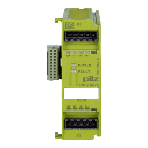
Pilz PNOZ m EF 8DI4DO User manual

Pilz

Pilz PNOZ m EF 8DI4DO User manual

Pilz PNOZ mc6.1p User manual

Pilz

Pilz PNOZ mc6.1p User manual

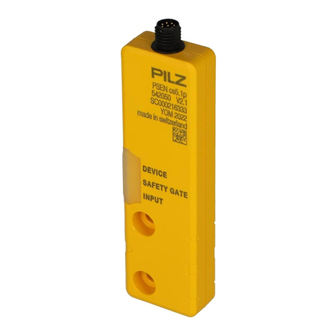
Pilz PSEN cs5.1p User manual

Pilz

Pilz PSEN cs5.1p User manual

Pilz PSEN ma1.4n-51 User manual

Pilz

Pilz PSEN ma1.4n-51 User manual

Pilz PNOZ ms3p User manual

Pilz

Pilz PNOZ ms3p User manual

Pilz PSSu E F 4DO 0.5 User manual

Pilz

Pilz PSSu E F 4DO 0.5 User manual

Pilz PNOZ m ES CANopen User manual

Pilz

Pilz PNOZ m ES CANopen User manual

Pilz PNOZmulti 2 User manual

Pilz

Pilz PNOZmulti 2 User manual

Pilz PITmode flex visu User manual

Pilz

Pilz PITmode flex visu User manual

Pilz PSS u2 ES 8DI User manual

Pilz

Pilz PSS u2 ES 8DI User manual

Pilz PSSu K S RS232 Modbus ASCII User manual

Pilz

Pilz PSSu K S RS232 Modbus ASCII User manual

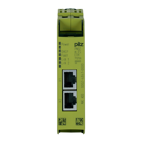
Pilz PNOZ m ES ETH User manual

Pilz

Pilz PNOZ m ES ETH User manual

Pilz PNOZ m ES Profibus User manual

Pilz

Pilz PNOZ m ES Profibus User manual

Pilz PNOZ m EF 2MM User manual

Pilz

Pilz PNOZ m EF 2MM User manual

Pilz PSS CPU Series User manual

Pilz

Pilz PSS CPU Series User manual

Pilz PSSu E F 2DO 2 User manual

Pilz

Pilz PSSu E F 2DO 2 User manual

Pilz PNOZ s11 User manual

Pilz

Pilz PNOZ s11 User manual

Pilz PIT m3.3p User manual

Pilz

Pilz PIT m3.3p User manual

Pilz PSEN ma1.3a/b-22 User manual

Pilz

Pilz PSEN ma1.3a/b-22 User manual

Pilz PSSu E F 4DI User manual

Pilz

Pilz PSSu E F 4DI User manual

Pilz PNOZ mc1p User manual

Pilz

Pilz PNOZ mc1p User manual

Pilz PDP67 F 8DI ION User manual

Pilz

Pilz PDP67 F 8DI ION User manual

Pilz PNOZ m0p User manual

Pilz

Pilz PNOZ m0p User manual

Pilz PSS u2 ES 4DOD 0.5A User manual

Pilz

Pilz PSS u2 ES 4DOD 0.5A User manual

Popular Control Unit manuals by other brands

Comtech EF Data Vipersat CDM-570L Installation and operation manual

Comtech EF Data

Comtech EF Data Vipersat CDM-570L Installation and operation manual

Trenz Electronic TE0720-1QFGO Schematics

Trenz Electronic

Trenz Electronic TE0720-1QFGO Schematics

Elsist SlimLine PCB124B010 Hardware manual

Elsist

Elsist SlimLine PCB124B010 Hardware manual

resideo Braukmann L5 Series quick start guide

resideo

resideo Braukmann L5 Series quick start guide

INIM Flex5/R Installation and programming manual

INIM

INIM Flex5/R Installation and programming manual

SMC Networks ASP Series Operation manual

SMC Networks

SMC Networks ASP Series Operation manual

Spectracom SecureSync 1200 User reference guide

Spectracom

Spectracom SecureSync 1200 User reference guide

SSS Siedle BSG 650-02 manual

SSS Siedle

SSS Siedle BSG 650-02 manual

Metaltecnica 0080 Installation, operation & maintenance manual

Metaltecnica

Metaltecnica 0080 Installation, operation & maintenance manual

Texas Instruments TPS6381xEVM user guide

Texas Instruments

Texas Instruments TPS6381xEVM user guide

Honeywell V48F Product data

Honeywell

Honeywell V48F Product data

BENDIX LQ-2 QUICK RELEASE VALVES manual

BENDIX

BENDIX LQ-2 QUICK RELEASE VALVES manual

Digiplex DGP2-ZX1 Reference manual

Digiplex

Digiplex DGP2-ZX1 Reference manual

Siemens SIPROTEC4 7SJ61 manual

Siemens

Siemens SIPROTEC4 7SJ61 manual

Supermicro MicroBlade MBI-6118D-T2 user manual

Supermicro

Supermicro MicroBlade MBI-6118D-T2 user manual

Vag Figures 250-D Installation, operation and maintenance manual

Vag

Vag Figures 250-D Installation, operation and maintenance manual

Flight Systems 56-0679-00 Product information

Flight Systems

Flight Systems 56-0679-00 Product information

Comeup 882756 manual

Comeup

Comeup 882756 manual

manuals.online logo
manuals.online logoBrands
  • About & Mission
  • Contact us
  • Privacy Policy
  • Terms and Conditions

Copyright 2025 Manuals.Online. All Rights Reserved.