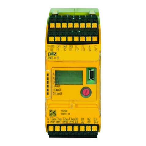
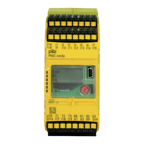
Pilz PNOZ m C0 User manual

PNOZ m C0
Operating Manual-1006013-EN-02
}Configurable, safe small controllers PNOZmulti 2

Preface
This document is the original document.
Where unavoidable, for reasons of readability, the masculine form has been selected when
formulating this document. We do assure you that all persons are regarded without discrim-
ination and on an equal basis.
All rights to this documentation are reserved by Pilz GmbH & Co. KG. Copies may be made
for the user's internal purposes. Suggestions and comments for improving this documenta-
tion will be gratefully received.
Pilz®, PIT®, PMI®, PNOZ®, Primo®, PSEN®, PSS®, PVIS®, SafetyBUS p®,
SafetyEYE®, SafetyNET p®, the spirit of safety® are registered and protected trademarks
of Pilz GmbH & Co. KG in some countries.
SD means Secure Digital

Contents
Operating Manual PNOZ m C0
1006013-EN-02 | 3
1 Introduction ............................................................................................................................5
1.1 Validity of documentation ..........................................................................................................5
1.2 Using the documentation ..........................................................................................................5
1.3 Definition of symbols .................................................................................................................5
1.4 Third-party manufacturer licence information............................................................................6
2 Overview .................................................................................................................................7
2.1 Range........................................................................................................................................7
2.2 Unit features..............................................................................................................................7
2.3 Chip card...................................................................................................................................8
2.4 Front view..................................................................................................................................8
3 Safety ......................................................................................................................................10
3.1 Intended use .............................................................................................................................10
3.2 Applicable documentation .........................................................................................................11
3.3 System requirements ................................................................................................................11
3.4 Safety regulations .....................................................................................................................11
3.4.1 Safety assessment....................................................................................................................11
3.4.2 Use of qualified personnel.........................................................................................................11
3.4.3 Warranty and liability.................................................................................................................11
3.4.4 Disposal ....................................................................................................................................12
3.4.5 For your safety ..........................................................................................................................12
4 Security ...................................................................................................................................13
4.1 Implemented security measures ...............................................................................................13
4.2 Required security measures .....................................................................................................13
5 Function description ..............................................................................................................15
5.1 Integrated protection mechanisms............................................................................................15
5.2 Functions...................................................................................................................................15
5.3 Reaction times ..........................................................................................................................15
5.4 Block diagram ...........................................................................................................................16
5.5 Diagnostics................................................................................................................................16
5.6 Device security..........................................................................................................................16
5.6.1 User management.....................................................................................................................16
5.6.2 Security device key ...................................................................................................................17
6 Installation ..............................................................................................................................19
6.1 Control cabinet installation ........................................................................................................19
6.1.1 Mounting distances ...................................................................................................................20
6.2 Dimensions in mm.....................................................................................................................21
7 Commissioning ......................................................................................................................22
7.1 General wiring guidelines..........................................................................................................22
7.2 Connection ................................................................................................................................22
7.3 Load project from chip card.......................................................................................................24
7.4 Load project via USB port ........................................................................................................24
7.5 Function test during commissioning..........................................................................................24
Contents
Operating Manual PNOZ m C0
1006013-EN-02 | 4
7.6 Using the chip card ..................................................................................................................25
7.7 Connection example .................................................................................................................26
8 Operation ................................................................................................................................27
9 Factory reset ...........................................................................................................................28
10 Maintenance and testing .......................................................................................................29
11 Technical details ....................................................................................................................30
11.1 Safety characteristic data..........................................................................................................33
11.2 Classification according to ZVEI, CB24I ...................................................................................34
12 Supplementary data ...............................................................................................................35
12.1 Maximum capacitive load C (μF) with load current I (A) at the semiconductor outputs ............35
12.2 Permitted ambient temperature Tamb dependent on the total current Isum ............................35
13 Order reference ......................................................................................................................36
13.1 Product......................................................................................................................................36
13.2 Accessories...............................................................................................................................36
13.2.1 Replacement terminals .............................................................................................................36
13.2.2 Cable.........................................................................................................................................36
14 EC declaration of conformity ................................................................................................37
15 UKCA-Declaration of Conformity .........................................................................................38

Introduction
Operating Manual PNOZ m C0
1006013-EN-02 | 5
1 Introduction
1.1 Validity of documentation
This documentation is valid for the product PNOZ m C0 from Version HW:01, FW:01.01.
This operating manual explains the function and operation, describes the installation and
provides guidelines on how to connect the product.
1.2 Using the documentation
This document is intended for instruction. Only install and commission the product if you
have read and understood this document. The document should be retained for future ref-
erence.
1.3 Definition of symbols
Information that is particularly important is identified as follows:
DANGER!
This warning must be heeded! It warns of a hazardous situation that poses
an immediate threat of serious injury and death and indicates preventive
measures that can be taken.
WARNING!
This warning must be heeded! It warns of a hazardous situation that could
lead to serious injury and death and indicates preventive measures that can
be taken.
CAUTION!
This refers to a hazard that can lead to a less serious or minor injury plus
material damage, and also provides information on preventive measures
that can be taken.
NOTICE
This describes a situation in which the product or devices could be dam-
aged and also provides information on preventive measures that can be
taken. It also highlights areas within the text that are of particular import-
ance.

Introduction
Operating Manual PNOZ m C0
1006013-EN-02 | 6
INFORMATION
This gives advice on applications and provides information on special fea-
tures.
1.4 Third-party manufacturer licence information
This product includes Open Source software with various licenses.
Further information is available in the document "Third-party manufacturer licence informa-
tion PNOZ m C0" (document number 1006087) at www.pilz.com.

Overview
Operating Manual PNOZ m C0
1006013-EN-02 | 7
2 Overview
2.1 Range
}Base unit PNOZ m C0
2.2 Unit features
Application of the product PNOZ m C0:
Standalone base unit of the configurable control system PNOZmulti 2
The product has the following features:
}Can be configured in the PNOZmulti Configurator
}Semiconductor outputs:
4 safety outputs
depending on the application, up to PL e of EN ISO 13849-1 and up to SIL 3 of EN IEC
62061
}8 safe inputs for connecting, for example:
– Emergency stop pushbuttons
– Two-hand pushbuttons
– Safety gate limit switches
– Start buttons
– Light barriers
– Scanner
– Enabling switches
– PSEN
– Operating mode selector switches
Alternatively, inputs IM0 and IM1 can be configured as signal outputs.
The pulse suppression time for the inputs can be changed in the PNOZmulti Configurator.
A change of the preset pulse suppression time (see Technical details [ 30]) can be
used to suppress the self-monitored outputs and for interference suppression.
}2 configurable outputs
Can be configured as:
– Test pulse outputs
or
– Signal outputs
}LED display for:
– Supply voltage
– Run operating state
– Diagnostics
– Internal and external fault
– Fault at the outputs

Overview
Operating Manual PNOZ m C0
1006013-EN-02 | 8
– Fault at the inputs
}Test pulse outputs used to monitor shorts across the inputs
}Monitoring of shorts between the safety outputs
}Plug-in connection terminals:
Either spring-loaded terminal or screw terminal available as accessories (see Order refer-
ences)
2.3 Chip card
As an option, a chip card can be used to transfer project data.
Chip cards with 8 kByte and 32 kByte memories are available. For large-scale projects we
recommend the 32 kByte chip card (see Technical Catalogue: Accessories).
2.4 Front view
Hardware version (HW)
Firmware version (FW)
Order number
Serial number
Legend
X1: Inputs I4 ... I7
X2: Semiconductor outputs O0 ... O3
X3: Configurable inputs/outputs IM0 and IM1
Inputs I2 ... I3
X4: Configurable test pulse/auxiliary outputs T0M20 and T1M21
Supply connections 24 V and 0 V

Overview
Operating Manual PNOZ m C0
1006013-EN-02 | 9
LEDs: Power
Run
Diag
Fault
I Fault
O Fault

Safety
Operating Manual PNOZ m C0
1006013-EN-02 | 10
3 Safety
3.1 Intended use
The standalone base unit PNOZ m C0 is used for the safety-related interruption of safety
circuits and is designed for use in:
}Emergency stop equipment
}Safety circuits in accordance with VDE0113 Part 1 and EN60204-1
CAUTION!
Inputs and outputs for standard functions must not be used for safety-re-
lated applications.
Lifts Directive
The product PNOZ m C0 can be used as a PESSRAL (programmable electronic system in
safety-related applications for lifts) in accordance with the Lifts Directive 2014/33/EU. It
meets the requirements for passenger and goods lifts in accordance with EN 81-1/2, EN
81-20, EN 81-22 and EN 81-50, as well as the requirements for escalators and moving
walks in accordance with EN 115-1.
The safety controller should be installed in a protected environment that meets at least the
requirements of pollution degree 2.
Example: Protected inside space or control cabinet with protection type IP54 and appropri-
ate air conditioning.
Year of manufacture
The year of manufacture is specified on the product after the reference YOM (Year of Man-
ufacturing).
Improper use
The following is deemed improper use in particular
}Any component, technical or electrical modification to the product,
}Use of the product outside the areas described in this operating manual,
}Use of the product outside the technical details (see Technical details [ 30]).
NOTICE
EMC-compliant electrical installation
The product is designed for use in an industrial environment. The product
may cause interference if installed in other environments. If installed in other
environments, measures should be taken to comply with the applicable
standards and directives for the respective installation site with regard to in-
terference.

Safety
Operating Manual PNOZ m C0
1006013-EN-02 | 11
3.2 Applicable documentation
This document includes only part of the information required for the use of the device. To
understand and correctly use the product you must read further documents.
Please read the following documents:
}"PNOZmulti Safety Manual"
}"PNOZmulti Installation Manual"
}The advanced functions of the device are described in the online help for the PNOZmulti
Configurator and in the document "PNOZmulti Special Applications". Only use these func-
tions once you have read and understood the documentation.
3.3 System requirements
Please refer to the "Product Modifications" document in the "Version overview" section for
details of which versions of the PNOZmulti Configurator can be used for this product.
3.4 Safety regulations
3.4.1 Safety assessment
Before using a device, a safety assessment in accordance with the Machinery Directive is
required.
The product as an individual component fulfils the functional safety requirements in accord-
ance with EN ISO 13849 and EN 62061. However, this does not guarantee the functional
safety of the overall plant/machine. To achieve the relevant safety level of the overall plant/
machine’s required safety functions, each safety function needs to be considered separ-
ately.
3.4.2 Use of qualified personnel
The products may only be assembled, installed, programmed, commissioned, operated,
maintained and decommissioned by persons who are competent to do so.
A competent person is a qualified and knowledgeable person who, because of their train-
ing, experience and current professional activity, has the specialist knowledge required. To
be able to inspect, assess and operate devices, systems and machines, the person has to
be informed of the state of the art and the applicable national, European and international
laws, directives and standards.
It is the company’s responsibility only to employ personnel who
}Are familiar with the basic regulations concerning health and safety / accident prevention,
}Have read and understood the information provided in the section entitled Safety
}Have a good knowledge of the generic and specialist standards applicable to the specific
application.
3.4.3 Warranty and liability
All claims to warranty and liability will be rendered invalid if
}The product was used contrary to the purpose for which it is intended,

Safety
Operating Manual PNOZ m C0
1006013-EN-02 | 12
}Damage can be attributed to not having followed the guidelines in the manual,
}Operating personnel are not suitably qualified,
}Any type of modification has been made (e.g. exchanging components on the PCB
boards, soldering work etc.).
3.4.4 Disposal
}In safety-related applications, please comply with the mission time TM in the safety-related
characteristic data.
}When decommissioning, please comply with local regulations regarding the disposal of
electronic devices (e.g. Electrical and Electronic Equipment Act).
3.4.5 For your safety
The unit meets all the necessary conditions for safe operation. However, you should always
ensure that the following safety requirements are met:
}This operating manual only describes the device's basic functions. The advanced func-
tions are described in the online help for the PNOZmulti Configurator and in the docu-
ment "PNOZmulti Special Applications". Only use these functions once you have read
and understood the documentation.
}Please note the "PNOZmulti Installation Manual".
}You must note the information stated in the "PNOZmulti Safety Manual".
}Adequate protection must be provided for all inductive consumers.
}Do not open the housing or make any unauthorised modifications.
}Please make sure you shut down the supply voltage when performing maintenance work
(e.g. exchanging contactors).

Security
Operating Manual PNOZ m C0
1006013-EN-02 | 13
4 Security
To secure plants, systems, machines and networks against cyberthreats it is necessary to
implement (and continuously maintain) an overall industrial security concept that is state of
the art.
Perform a risk assessment in accordance with VDI/VDE 2182 or IEC 62443-3-2 and plan
the security measures with care. If necessary, seek advice from Pilz Customer Support.
4.1 Implemented security measures
}To carry out relevant operations in the PNOZmulti Configurator, a user must authenticate
himself on the device with user name and password.
}Multiple users with different permissions can be created and configured in the PNOZmulti
Configurator.
The user data is transmitted to the device and stored there.
}In the base unit PNOZ m C0 a security device key can be stored.
The security device key includes the following functions:
– Verifiable trust anchor in the device for the plant manufacturer.
In the PNOZmulti Configurator you can verify whether a device key from device key
management matches the device key on the connected device.
– Ensure the authenticity of project data on the chip card
The base unit PNOZ m C0 accepts project data on the chip card only if it has been
generated using the identical security device key.
4.2 Required security measures
}The product is not protected from physical manipulation or from reading of memory con-
tents during physical access. Use appropriate measures to ensure that there is no phys-
ical access by unauthorised persons. You should also use security seals so that you can
detect any manipulation of the product or interfaces. Installation inside a lockable control
cabinet is recommended as a minimum measure.
}Protect the configuration and log data from unauthorised changes.
}Check the product's log for unauthorised program changes on a regular basis.
}A factory-set default password is active on the base unit along with permissions for users
who are not logged in. Change the password immediately after logging in for the first
time.
}Assign different permissions for the various user groups (e.g. diagnostics - configuration).
}The project data on the chip card is not protected when the security device key is not
used, and it can be read by unauthorised persons.
– Use the security device key to protect the project data during transfer
or
– Remove the chip card.
}Assign only safe passwords. When assigning passwords, please note:
– The password should have at least 8 characters.
– The password should contain upper and lower case characters, as well as special
characters and numbers.

Security
Operating Manual PNOZ m C0
1006013-EN-02 | 14
– If possible, the password should not be available in dictionaries.
– The password should not be made up of standard variants and repetitions or key-
board patterns (so not: 1234abcd).
– Use a password manager for optimum management of complex passwords.
– Language-independent characters are not available in every keyboard language.
– Make sure you regularly change the passwords of the user accounts on the system
and/or ask the users to change their passwords themselves.
– Make the users aware of the responsible use of their access data.

Function description
Operating Manual PNOZ m C0
1006013-EN-02 | 15
5 Function description
5.1 Integrated protection mechanisms
The relay meets the following safety requirements:
}The circuit is redundant with built-in self-monitoring.
}The safety device remains effective in the case of a component failure.
}The safety outputs are tested periodically using a disconnection test.
5.2 Functions
The function of the inputs and outputs on the control system depends on the user program
created using the PNOZmulti Configurator. The user program is transferred to the base unit
via chip card or via the USB port. The base unit has 2 microcontrollers that monitor each
other. They evaluate the base unit's input circuits and switch the outputs accordingly.
The LEDs on the base unit indicate the status of the configurable control system
PNOZmulti.
The online help for the PNOZmulti Configurator contains descriptions of the operating
modes and all the functions of the control system, plus connection examples.
5.3 Reaction times
t ReactionMax = t Max input delay + t Max processing time. + t Max switch-off delay at
the output
Please note that the reaction time is also increased by
}Delay times configured in the user program
}Delay on the sensor that is used
}Delay on the actuator that is used
Example configuration: PNOZ m C0
Input
PNOZ m C0
Max. input delay
Processing in the user
program
Processing time
Output
PNOZ m C0
Switch-off delay
14ms 5 ms 1 ms
tReactionMax = 14 ms + 5 ms + 1 ms
tReactionMax = 20 ms

Function description
Operating Manual PNOZ m C0
1006013-EN-02 | 16
5.4 Block diagram
5.5 Diagnostics
The status and error messages displayed by the LEDs are saved in an error stack. This er-
ror stack can be read out from PNOZmulti Configurator via the USB interface.
5.6 Device security
5.6.1 User management
The base unit PNOZ m C0 can be protected from unauthorised access via user manage-
ment.
In order to access the device or perform specific actions via the PNOZmulti Configurator, a
user must use his credentials to authenticate himself.
A user account can be created for each user in the PNOZmulti Configurator's user manage-
ment.
There are user groups that have access permissions with pre-defined permissions.
A user group is assigned to each user account.
Each user account obtains a unique user name and a password.
When you log into a new device for the first time or after a factory reset has been per-
formed, use the factory-set default credentials to log in as administrator:
Login name admin
Password pilz
As administrator you have all the available permissions. Change the default password im-
mediately after logging in for the first time.
User management is configured in the PNOZmulti Configurator and transferred to the
device.
Detailed information on user management and how it is configured can be found in the on-
line help for the PNOZmulti Configurator.

Function description
Operating Manual PNOZ m C0
1006013-EN-02 | 17
5.6.2 Security device key
In the base unit PNOZ m C0 a security device key can be stored.
NOTICE
Please note:
When replacing this device in future, a new matching security device key
must be present on the new device
The security device key includes the following functions:
}Verifiable trust anchor in the device for the plant manufacturer. In the PNOZmulti Config-
urator you can verify whether a device key from device key management matches the
device key on the connected device.
}Ensure authenticity of project data on the chip card
The PNOZ m C0 accepts project data on the chip card only if it has been generated using
the identical security device key. This happens automatically when project data is trans-
ferred via the PNOZmulti Configurator or by selecting the correct security device key
when the project data is saved directly to the chip card using the PNOZmulti Configurator.
The project data is saved on the chip card in encrypted form.
The security device key is generated, edited, written and verified in the PNOZmulti Con-
figurator in security device key management.
CAUTION!
Please note:
An encrypted project can only be decoded using the matching security
device key. When the security device key is lost, the device can no longer
be decoded.
CAUTION!
When using a chip card, please note:
After the security device key has been changed, the project data on the chip
card is no longer trustworthy.
– Load the project data on to the device again via the PNOZmulti Con-
figurator
or
– Remove the chip card
A factory reset resets the security device key.
Users who are signed in as administrators can overwrite the security device key. In this
case, a prior factory reset is not required.

Function description
Operating Manual PNOZ m C0
1006013-EN-02 | 18
NOTICE
Please note
To write a device key to a device, the device must be in stop state.

Installation
Operating Manual PNOZ m C0
1006013-EN-02 | 19
6 Installation
6.1 Control cabinet installation
}The unit should be installed in a control cabinet with a protection type of at least IP54.
}Install the system vertically on to a horizontal mounting rail. The venting slots must face
upward and downward. Other mounting positions could damage the safety system.
}Use the locking elements on the rear of the unit to attach it to a mounting rail.
}In environments exposed to heavy vibration, the unit should be secured using a fixing ele-
ment (e.g. retaining bracket or end angle).
}Open the locking slide before lifting the unit from the mounting rail.
}To comply with EMC requirements, the mounting rail must have a low impedance con-
nection to the control cabinet housing.
NOTICE
Damage due to electrostatic discharge!
Electrostatic discharge can damage components. Ensure against discharge
before touching the product, e.g. by touching an earthed, conductive sur-
face or by wearing an earthed armband.

Installation
Operating Manual PNOZ m C0
1006013-EN-02 | 20
6.1.1 Mounting distances
With control cabinet installation it is essential to maintain a certain distance from the top
and bottom, as well as to other heat-producing devices (see diagram). The values stated
for the mounting distances are minimum specifications.
The ambient temperature of the product in the control cabinet must not exceed the figure
stated in the technical details, otherwise air conditioning may be required.
Mounting distances:
Heat-generating device
INFORMATION
Please note that at the stated minimum distance, it will be difficult to swap
the chip card from above. If you cannot leave a greater distance, remove
the unit from the mounting rail to swap the chip card.
Table of contents
Other Pilz Controllers manuals

Pilz
Pilz PSEN sl-1.0p 4.2 User manual

Pilz
Pilz PSEN 2.1b-26 User manual

Pilz
Pilz PNOZ m EF Multi Link User manual

Pilz
Pilz PNOZ mo3p User manual

Pilz
Pilz PSEN op67-69K Series User manual

Pilz
Pilz PNOZmulti PNOZ mmc3p User manual

Pilz
Pilz PSEN ma1.4a-57 User manual

Pilz
Pilz PSEN sl-0.5n 1.1 User manual

Pilz
Pilz PSEN sl-1.0p 3.1 User manual

Pilz
Pilz PSS Series User manual

Pilz
Pilz PNOZ m EF 1MM User manual

Pilz
Pilz PITmode flex User manual

Pilz
Pilz PSS Series User manual

Pilz
Pilz PNOZ mc1p User manual

Pilz
Pilz PNOZ mm0.2p User manual

Pilz
Pilz PNOZ mml1p User manual

Pilz
Pilz PNOZ m EF SafetyNET User manual

Pilz
Pilz PIT js2 User manual

Pilz
Pilz PNOZ m B0 User manual

Pilz
Pilz PNOZ m3p (ETH) User manual