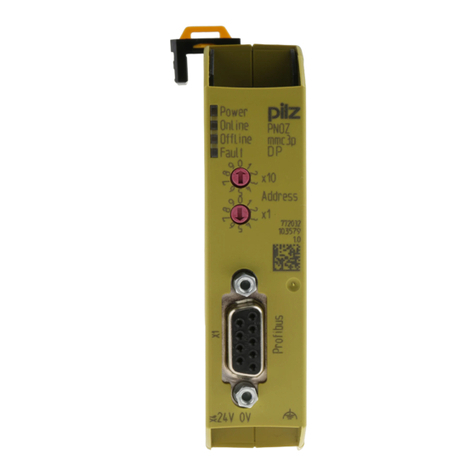
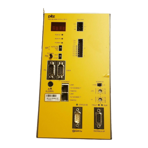
Pilz PSSuniversal multi PSSu H m F DP ETH SD User manual

PSSuHmFDPETHSD
OperatingManual1002323EN04
ControlsystemPSSuniversalmulti

Preface
Thisdocumentistheoriginaldocument.
AllrightstothisdocumentationarereservedbyPilzGmbH&Co.KG.Copiesmaybemade
forinternalpurposes.Suggestionsandcommentsforimprovingthisdocumentationwillbe
gratefullyreceived.
Pilz®,PIT®,PMI®,PNOZ®,Primo®,PSEN®,PSS®,PVIS®,SafetyBUSp®,
SafetyEYE®,SafetyNETp®,thespiritofsafety®areregisteredandprotectedtrademarks
ofPilzGmbH&Co.KGinsomecountries.
SDmeansSecureDigital

Content
OperatingManualPSSuHmFDPETHSD
1002323EN04 3
Section1 Introduction 5
1.1 Validityofthedocumentation 5
1.1.1 Retainingthedocumentation 5
1.2 Definitionofsymbols 5
Section2 Overview 7
2.1 Modulefeatures 7
2.2 Frontview 7
Section3 Safety 9
3.1 Intendeduse 9
3.2 Safetyregulations 9
3.2.1 Useofqualifiedpersonnel 9
3.2.2 Warrantyandliability 9
3.2.3 Disposal 10
Section4 Functiondescription 11
4.1 Blockdiagram 11
4.2 Controlsystem 11
4.3 Supplyvoltage 11
4.3.1 Functiondescription 11
4.3.2 Currentloadcapacity 12
4.4 Integratedprotectionmechanisms 12
4.5 SDcard 13
4.6 Resetbutton 13
4.7 PROFIBUSDP 14
4.7.1 ConnectiontoPROFIBUSDP 14
4.7.2 Selectorswitchforsettingthestationaddress 14
4.8 EthernetInterface 14
4.8.1 RJ45interfaces("Ethernet") 14
4.8.2 RJ45connectioncable 15
Section5 Installation 16
5.1 Generalinstallationguidelines 16
5.2 Dimensions 16
5.3 Installingtheheadmodule 16
Section6 Interfaces 18
6.1 Interfaceconfiguration 18
6.1.1 PROFIBUSDP 18
6.1.2 Ethernet 18
Section7 Wiring 20
7.1 Generalwiringguidelines 20
7.2 Terminalconfiguration 20
7.3 Connectingthemodule 21

Content
OperatingManualPSSuHmFDPETHSD
1002323EN04 4
Section8 Operation 22
8.1 Messages 22
8.2 Displayelements 22
8.2.1 MBUS 23
8.2.2 SDCARD 24
8.2.3 FSRUN 25
8.2.4 DIAG 26
8.2.5 FSFORCE 27
8.2.6 SF,BF 28
8.2.7 5V,24V 28
8.2.8 X3:LNK,X3:TRF 29
Section9 Technicaldetails 30
9.1 Safetycharacteristicdata 33
Section10 Orderreference 34
10.1 Product 34
10.2 Accessories 34

Introduction
OperatingManualPSSuHmFDPETHSD
1002323EN04 5
1 Introduction
1.1 Validityofthedocumentation
ThisdocumentationisvalidfortheproducttypePSSuHmFDPETHSD.Itisvaliduntil
newdocumentationispublished.
Pleasealsorefertothefollowingdocuments:
}PSS4000SystemDescription
}PSSuniversalInstallationManual
Thisoperatingmanualexplainsthefunctionandoperation,describestheinstallationand
providesguidelinesonhowtoconnecttheproduct.
1.1.1 Retainingthedocumentation
Thisdocumentationisintendedforinstructionandshouldberetainedforfuturereference.
1.2 Definitionofsymbols
Informationthatisparticularlyimportantisidentifiedasfollows:
DANGER!
Thiswarningmustbeheeded!Itwarnsofahazardoussituationthatposes
animmediatethreatofseriousinjuryanddeathandindicatespreventive
measuresthatcanbetaken.
WARNING!
Thiswarningmustbeheeded!Itwarnsofahazardoussituationthatcould
leadtoseriousinjuryanddeathandindicatespreventivemeasuresthatcan
betaken.
CAUTION!
Thisreferstoahazardthatcanleadtoalessseriousorminorinjuryplus
materialdamage,andalsoprovidesinformationonpreventivemeasures
thatcanbetaken.

Introduction
OperatingManualPSSuHmFDPETHSD
1002323EN04 6
NOTICE
Thisdescribesasituationinwhichtheproductordevicescouldbedam
agedandalsoprovidesinformationonpreventivemeasuresthatcanbe
taken.Italsohighlightsareaswithinthetextthatareofparticularimport
ance.
INFORMATION
Thisgivesadviceonapplicationsandprovidesinformationonspecialfea
tures.

Overview
OperatingManualPSSuHmFDPETHSD
1002323EN04 7
2 Overview
2.1 Modulefeatures
Theheadmodulebelongstotheperformanceclass"ControlsystemPSSumulti".Thehead
modulehasthefollowingfeatures:
}Ethernetinterfacefor
– Projectdownload
– Readthediagnosticdata
}PROFIBUSDPinterface
}anFSresource
}SDcardusedtostorethedeviceprojectandthenamingdata
}Resetbutton
– Forwarmreset
– Totransferthenamingdataand/ordeviceprojectfromtheSDcardtothedevice
memory
}Supplyvoltage
– Integratedsupplyvoltageforperipherysupplyandmodulesupply
– Modulesupplyisbufferedfor20msifthesupplyvoltageisinterrupted
– Pluginconnectionterminals(eitherspringloadedterminalorscrewterminal)
}StatusLEDs
}SupportsFSandSTmodules
2.2 Frontview
MBUS
SD CARD
FS RUN
DIAG
FS FORCE
X3: LNK
X3: TRF
5V
24V
PSSu H
mF DP ETH SD
Reset
24V 24V 0V 0V
X2
24V C 0V
X1
X3
MAC
ADD
0000
0000
0000
312060
000000
HW 000
PSSu multi
SD
PSS 4000
SF
BF
ADDRESS
OFF ON
- -
64
32
16
8
4
2
1
- -
PROFIBUS DP
X4
ETHERNET
2
3
4
5
6
7
1
4

Overview
OperatingManualPSSuHmFDPETHSD
1002323EN04 8
Key:
}1:ETHERNETinterface
}2:PROFIBUSDPinterface
}3:Labellingstrip(seebelowfordetails)
}4:StatusLEDs
}5:SDcard
}6:Resetbutton
}7:Supplyvoltageconnection(moduleandperipherysupply)
Thelabellingstripcontainsthefollowinginformation:
Order number
Serial number
Hardware version
2D code:
Product
information
MAC address
2D code:
MAC address
MAC
ADD
0002
4840
3152
312060
100017
HW 001

Safety
OperatingManualPSSuHmFDPETHSD
1002323EN04 9
3 Safety
3.1 Intendeduse
Themoduleisdesignedforusein:
}Safetyrelatedapplicationswith
– PROFIBUSDPwithlocalenableprinciple
}Nonsafetyrelatedapplicationswith
– PROFIBUSDP
IntendeduseincludesmakingtheelectricalinstallationEMCcompliant.Pleaserefertothe
guidelinesstatedinthe"PSSuniversalInstallationManual".Themoduleisdesignedforuse
inanindustrialenvironment.Itisnotsuitableforuseinadomesticenvironment,asthiscan
leadtointerference.
Thefollowingisdeemedimproperuseinparticular:
}Anycomponent,technicalorelectricalmodificationtothemodule
}Useofthemoduleoutsidetheareasdescribedinthismanual
}Anyuseofthemodulethatisnotinaccordancewiththetechnicaldetails.
INFORMATION
ThemoduleissupportedbyPAS4000fromVersion1.5.0.Werecommend
thatyoualwaysusethelatestversion(downloadfromwww.pilz.de).
3.2 Safetyregulations
3.2.1 Useofqualifiedpersonnel
Theproductsmayonlybeassembled,installed,programmed,commissioned,operated,
maintainedanddecommissionedbycompetentpersons.
Acompetentpersonissomeonewho,becauseoftheirtraining,experienceandcurrentpro
fessionalactivity,hasthespecialistknowledgerequiredtotest,assessandoperatethe
workequipment,devices,systems,plantandmachineryinaccordancewiththegeneral
standardsandguidelinesforsafetytechnology.
Itisthecompany’sresponsibilityonlytoemploypersonnelwho:
}Arefamiliarwiththebasicregulationsconcerninghealthandsafety/accidentpreven
tion
}Havereadandunderstoodtheinformationprovidedinthisdescriptionunder"Safety"
}Andhaveagoodknowledgeofthegenericandspecialiststandardsapplicabletothe
specificapplication.
3.2.2 Warrantyandliability
Allclaimstowarrantyandliabilitywillberenderedinvalidif
}Theproductwasusedcontrarytothepurposeforwhichitisintended
}Damagecanbeattributedtonothavingfollowedtheguidelinesinthemanual

Safety
OperatingManualPSSuHmFDPETHSD
1002323EN04 10
}Operatingpersonnelarenotsuitablyqualified
}Anytypeofmodificationhasbeenmade(e.g.exchangingcomponentsonthePCB
boards,solderingworketc.).
3.2.3 Disposal
}Insafetyrelatedapplications,pleasecomplywiththemissiontimeTMinthesafetyre
latedcharacteristicdata.
}Whendecommissioning,pleasecomplywithlocalregulationsregardingthedisposalof
electronicdevices(e.g.ElectricalandElectronicEquipmentAct).

Functiondescription
OperatingManualPSSuHmFDPETHSD
1002323EN04 11
4 Functiondescription
4.1 Blockdiagram
Module Bus
Module
Supply
+ 5 V DC
Data
(FS/ST)
Configu-
ration
Configu-
ration
Periphery
Supply
+ 24 V DC
=
=
Power
Periphery
Supply
Power
Module
Supply
24V 0V C24V 0V
SD Card
PROFIBUS DP
5
9
1
6
Data
(ST)
Ethernet
4.2 Controlsystem
Theheadmoduleisaprogrammablelogiccontroller(PLC),whichcanbeusedinsafetyre
latedandnonsafetyrelatedapplications.Thecontrolsystemhasmemoryareasfortheop
eratingsystem,thedataandthedeviceprojectwiththeuserprogram.
UserprogramscanbecreatedinMultiprogramming.
Forsafetyrelatedapplications,theprocessorsectionisdesignedwithmultichanneldi
versity.
Thecontrolsystemcommunicateswiththeinputandoutputmodulesviathelocalmodule
bus.
LEDsprovideinformationonthestatusofthecontrolsystemandindicateanyerrors.
4.3 Supplyvoltage
4.3.1 Functiondescription
Theproductprovidesthemodulesupplyandperipherysupplyforthemodulesonthemod
ulebus:
}Modulesupply
Supplyvoltageforsubsequentmodule(righthandside)
}Peripherysupply
Supplyvoltageforsensors,actuatorsandtestpulses
Whenthesupplyvoltageisfedinseparately,themodulesupplyandperipherysupplyare
galvanicallyisolated.Ifgalvanicisolationisnotrequired,acommonpowersupplymaybe
usedfortheperipherysupplyandmodulesupply.

Functiondescription
OperatingManualPSSuHmFDPETHSD
1002323EN04 12
4.3.2 Currentloadcapacity
Ensureyoucomplywiththecurrentloadcapacityofthemoduleandperipherysupply(see
"TechnicalDetails").Ifthecurrentloadishigher,anadditionalsupplyvoltagemoduleisre
quiredtorefreshthemodulesupplyandperipherysupply.
}Modulesupply
Thecurrentloadisthetotalcurrentconsumptionofalltheelectronicandcompactmod
ules.
Themodulesupplydoesnotautomaticallyswitchoffifvaluesexceedordropbelow
theirlimits.However,the"5V"LEDwilllightandamessagewillbeenteredinthedia
gnosticlist.
}Peripherysupply
Thecurrentloadisthetotalcurrentconsumptionofthesensors,actuatorsandtest
pulsessuppliedviatheinput/outputmodules.
Theperipherysupplydoesnotautomaticallyswitchoffifvaluesexceedordropbelow
theirlimits.However,the"24V"LEDwilllightandamessagewillbeenteredinthedia
gnosticlist.
Pleaserefertothederatingdiagram.
Deratingdiagramforperipherysupply:TemperatureTdependentonloadcurrentI
T (°C)
20
40
60
80
100
0
1 2 3 4 5 6 7 8 9 10 I (A)
4.4 Integratedprotectionmechanisms
Themodulehasthefollowingprotectionmechanisms:
}Multichanneldiverseprocessorsection
}Cyclicalselftests
}PotentiallyisolatedPROFIBUSDPinterface
}Infeedformodulesupply
– Polarityprotection
– Voltagemonitoring

Functiondescription
OperatingManualPSSuHmFDPETHSD
1002323EN04 13
– Transientvoltagelimitation
– 20msvoltagebufferifthesupplyvoltageisinterrupted
}Modulesupply
– Shortcircuitproof
}Peripherysupply
– Voltagemonitoring(exceedingupper/lowerlimit)
4.5 SDcard
TheSDcardhasthefollowingfunctions:
}TheSDcardisusedtostorethenamingdataandthedeviceproject;seePSS4000
SystemDescription.
}TheSDcardispartofthesafetyconceptonPSS4000.IftheSDcardismissingorhas
beenswapped,thenexttimethePSSusystemisbooteditwillbeunabletoachievethe
operatingstatus"PSSuSysteminRUNconditionwithouterror".TheSDcardhasa
lockingmechanism,whichprotectsitfrombeingremovedfromthecardholderuninten
tionally.TheSDcardcanalsobesealedtoprotectitfrommanipulation,whetheracci
dentalorintentional.
SealingtheSDcardforadditionalprotection:
4.6 Resetbutton
The"Reset"buttonontheheadmodulehasvariousfunctions:
}PerformawarmresetforthePSSusystem
TheresetbuttoncanbeusedtoperformawarmresetforthePSSusystem.
}Transferthenamingdataand/ordeviceprojectfromtheSDcard(deliberateoperator
actiontotransferthenamingdataand/ordeviceprojectfromtheSDcardtothedevice
memory).
INFORMATION
Thewarmresetandthetransferofthenamingdataand/ordeviceproject
aredescribedinthe"PSS4000SystemDescription".Thisisalsowherethe
generaleffectsonthePSSusystemaredescribedindetail.

Functiondescription
OperatingManualPSSuHmFDPETHSD
1002323EN04 14
4.7 PROFIBUSDP
4.7.1 ConnectiontoPROFIBUSDP
PROFIBUSisanopenfieldbusstandardwhosecommunicationisdefinedintheinterna
tionalstandardsIEC61158andIEC61784.Furtherprovisionshavebeendefinedinspe
cificationspublishedbythePROFIBUSUserGroup.Thesespecificationsareavailable
fromPROFIBUSInternational(seewww.profibus.com).
4.7.2 Selectorswitchforsettingthestationaddress
Thestationaddressissetviathe"ADDRESS"DIPswitch.TheDIPswitchisbinarycoded.
Permittedstationaddressesareintherange0D...125D.Ifstationaddress126Dissetvia
theDIPswitch,theaddresscanbeassignedviatheMaster.TheSetSlaveAddresscom
mand(SSA)mustberunforthispurpose.
Thestationaddressissetasfollows:
"ADDRESS"DIPswitch Meaning Example:
Switchdesignation OFF ON Stationaddress
PSSu:26D
Fdevice:52D
Notconnected
ADDRESS
OFF ON
- -
64
32
16
8
4
2
1
- -
64 0 64D
32 0 32D
16 0 16D
8 0 8D
4 0 4D
2 0 2D
1 0 1D
INFORMATION
Thestationaddressshouldonlybesetwhenthemoduleisswitchedoff(no
voltageapplied).
Thesettingsareonlytransferredwhenbooting.Anychangesmadetothe
settingsduringoperationwillnotbetransferred.
4.8 EthernetInterface
4.8.1 RJ45interfaces("Ethernet")
TheEthernetinterfacecanbeusedforthefollowingonlineactions:
}Downloadtheproject
}Readthediagnosticdata

Functiondescription
OperatingManualPSSuHmFDPETHSD
1002323EN04 15
}Firmwareupdate
TheconnectionisestablishedviaaRJ45socket.
TheEthernetinterfaceisconfiguredinPAS4000(seedescriptioninchapter"Network"in
PAS4000'sonlinehelp).
4.8.2 RJ45connectioncable
RJ45connector
8pin
8
1
10BaseT cable or 100BaseTX cable
max. 100 m

Installation
OperatingManualPSSuHmFDPETHSD
1002323EN04 16
5 Installation
5.1 Generalinstallationguidelines
PleasealsorefertothePSSuniversalInstallationManual.
Thedescriptionbelowassumesthatthemountingrailisalreadyinstalled.
NOTICE
Damageduetoelectrostaticdischarge!
Electrostaticdischargecandamagecomponents.Ensureagainstdischarge
beforetouchingtheproduct,e.g.bytouchinganearthed,conductivesur
faceorbywearinganearthedarmband.
5.2 Dimensions
130 mm
(5.19'')
50 mm
(1.97'')
3,1 mm
(0.12'')
56,2 mm
(2.21'') 125,6 mm
(4.94'')
83,3 mm (3.28'')
79,1 mm
(3.11'')
32,1 mm
(1.26'')
5.3 Installingtheheadmodule
Prerequisite:
}Themountingrailmustbeinstalled.
Pleasenote:
}Allcontactsshouldbeprotectedfromcontamination.
Procedure:
}Installanendbrackettotheleftoftheheadmoduleorleaveenoughspaceforone.
}Slotthegrooveontheheadmoduleontothemountingrailfrombelow[1].
}Pushtheheadmodulebackasfarasitwillgo[2].

Installation
OperatingManualPSSuHmFDPETHSD
1002323EN04 17
}Makesurethatthelockingmechanisms[3]arepusheddownwards,connectingthe
modulefirmlytothemountingrail.
Schematicrepresentation:
[1]
[2]
[3]
[3]

Interfaces
OperatingManualPSSuHmFDPETHSD
1002323EN04 18
6 Interfaces
6.1 Interfaceconfiguration
6.1.1 PROFIBUSDP
TheheadmodulecanbeincorporatedintothePROFIBUSasslave.
PROFIBUSDP Layout
Female9pinDSUBcon
nectorconformstothe
guidelinesofthePROFIBUS
UserGroup(PNO)
1:n.c.
2:n.c.
3:RxD/TxDP(Bline)
4:CNTRP(RTS)
5:DGND(GNDext.)
6:VP(+5Vext.)
7:n.c.
8:RxD/TxDN(Aline)
9:n.c.
1
5
9
6
}n.c.=notconnected
ThePSSuisconnectedtoPROFIBUSDPviaRS485communication.ThePSSusupplies
thePROFIBUSDPbusterminatingresistorswithvoltage(+5VDC).
INFORMATION
ThetwodatalinesarealsocalledAandBonPROFIBUS.
AlwaysconnecttheAline("RxD/TxDN")totheAlinesofalltheother
PROFIBUSsubscribers.
TheBline("RxD/TxDP")shouldonlybeconnectedtotheBlinesofthe
otherPROFIBUSsubscribers.
Ifcommunicationisnotestablished,checktheconnectionsusingacontinu
itytester.
}ConnecttheconnectorhousingtotheshieldingonthePROFIBUScable.Thecon
nectorhousingshouldbeconnectedwithlowimpedancetothemountingrail.
CAUTION!
DonotusethesignalsVP(+5Vext.)andDGND(GNDext.)tosupply
voltagetoexternaldevices!Theyareexclusivelyusedtosupplythe
PROFIBUSDPbusterminatingresistors.
6.1.2 Ethernet
EthernetInterface

Interfaces
OperatingManualPSSuHmFDPETHSD
1002323EN04 19
RJ45socket
8pin PIN Standard Crossover
8 1
1 TD+(Transmit+) RD+(Receive+)
2 TD(Transmit) RD(Receive)
3 RD+(Receive+) TD+(Transmit+)
4 n.c. n.c.
5 n.c. n.c.
6 RD(Receive) TD(Transmit)
7 n.c. n.c.
8 n.c. n.c.

Wiring
OperatingManualPSSuHmFDPETHSD
1002323EN04 20
7 Wiring
7.1 Generalwiringguidelines
Pleasenote:
}Therequirementsofthesupplyvoltagescanbefoundinthechapterentitled"Technical
Details".
}Protectiveseparationmustbeensuredfortheexternalpowersuppliesthatgenerate
thesupplyvoltages.Failuretodosocouldresultinelectricshock.
}TheexternalpowersuppliesmustcomplywiththecurrentapplicablestandardEN
609501,EN61140,EN50178orEN615581.
}Themaximumcurrentloadfortheperipherysupplyonthemodulebusis10A.Please
refertothederatingdiagraminthechapterentitled"FunctionDescription".
}Earththe0Vsupplyontheperipherysupplyormonitoreachsupplygroupforearth
faults.
}Theconnectionofthe0Vsupplytothecentralearthbarorearthfaultmonitormustbe
inaccordancewithrelevantnationalregulations(e.g.EN602041,NFPA79:177,
NEC:Article250).
}Detailsoftheminimumrangeforconductorcrosssectionsonconnectionterminalscan
befoundinthesectionentitled"TechnicalDetails".
}Usecopperwiring.
7.2 Terminalconfiguration
Modulesupply Terminalconfiguration X1
4pinfemalecon
nector
24V +24Vinfeedformodule
supply
24V 24V 0V 0V
X2
24V 0V
X1
0V 0Vinfeedformodule
supply
Peripherysupply Terminalconfiguration X2
4pinfemalecon
nector
24V: +24Vinfeedforperi
pherysupply
24V 24V 0V 0V
X2
24V 0V
X1
0V 0Vinfeedforperiphery
supply
Functionalearth
Table of contents
Other Pilz Controllers manuals

Pilz
Pilz PSEN sl-1.0p 3.1 User manual

Pilz
Pilz PSEN sl-0.5p 1.1 User manual

Pilz
Pilz PNOZmulti Classic PNOZ ms3p TTL User manual

Pilz
Pilz PNOZ mmc4p User manual

Pilz
Pilz PSS 3075-3 Series User manual

Pilz
Pilz PMUT X1P User manual

Pilz
Pilz PSS Series User manual

Pilz
Pilz PSS DIO Z User manual

Pilz
Pilz PNOZ m B0 User manual

Pilz
Pilz PNOZ m EF Multi Link User manual

Pilz
Pilz PSEN sl-1.0p 4.2 User manual
Pilz
Pilz PNOZ mm0.2p User manual

Pilz
Pilz PNOZ m EF 8DI2DOT User manual

Pilz
Pilz PNOZ m B1 User manual
Pilz
Pilz PITmode flex User manual

Pilz
Pilz 20 748-03 User manual

Pilz
Pilz PKB-M User manual

Pilz
Pilz PNOZ mmc7p CC User manual

Pilz
Pilz PNOZ mc5p User manual

Pilz
Pilz PNOZ m EF SafetyNET User manual