Pilz PNOZ 2VJ User manual

- 1 -
Sicherheitsbestimmungen
• Das Gerät darf nur von Personen installiert
und in Betrieb genommen werden, die mit
dieser Bedienungsanleitung und den
geltenden Vorschriften über Arbeitssicher-
heit und Unfallverhütung vertraut sind.
Beachten Sie die VDE- sowie die örtlichen
Vorschriften, insbesondere hinsichtlich
Schutzmaßnahmen.
• Beim Transport, der Lagerung und im
Betrieb die Bedingungen nach EN 60068-
2-6 einhalten (s. technische Daten).
• Durch Öffnen des Gehäuses oder
eigenmächtige Umbauten erlischt jegliche
Gewährleistung.
• Montieren Sie das Gerät in einen Schalt-
schrank; Staub und Feuchtigkeit können
sonst zu Beeinträchtigungen der Funktio-
nen führen.
• Sorgen Sie an allen Ausgangskontakten
bei kapazitiven und induktiven Lasten für
eine ausreichende Schutzbeschaltung.
Bestimmungsgemäße Verwendung
Das Sicherheitsschaltgerät erfüllt Forderun-
gen der EN 60947-5-1, EN 60204-1 und
VDE 0113-1 und darf eingesetzt werden in
Anwendungen mit
• NOT-AUS-Tastern
• Schutztüren
Das Gerät ist nicht für die Absicherung von
berührungslosen Verdeckungen geeignet, da
kein dynamischer Start möglich ist.
Gerätebeschreibung
Das Sicherheitsschaltgerät PNOZ 2VJ ist in
einem P-93-Gehäuse untergebracht. Es wird
mit -24 V Gleichspannung versorgt.
Merkmale:
• Relaisausgänge: fünf Sicherheitskontakte
(Schließer), davon zwei Schließer
rückfallverzögert und ein Hilfskontakt
(Öffner), zwangsgeführt
• Verzögerungszeit für die beiden rückfall-
verzögerten Schließer getrennt einstellbar
• Vorzeitiges Rücksetzen der Verzögerungs-
zeit durch Öffnerkontakt möglich
• Anschlussmöglichkeit für NOT-AUS-
Taster, Schutztürgrenztaster und Start-
taster
• Statusanzeige
• Rückführkreis zur Überwachung externer
Schütze
• Pluspol liegt auf GND
Das Schaltgerät erfüllt folgende Sicherheits-
anforderungen:
• Schaltung ist redundant mit Selbstüber-
wachung aufgebaut.
• Sicherheitseinrichtung bleibt auch bei
Ausfall eines Bauteils wirksam.
• Bei jedem Ein-Aus-Zyklus der Maschine
wird automatisch überprüft, ob die Relais
der Sicherheitseinrichtung richtig öffnen
und schließen.
• Schaltgeräte besitzen eine elektronische
Sicherung.
Conseils préliminaires
• La mise en oeuvre de l'appareil doit être
effectuée par une personne spécialisée en
installations électriques, en tenant compte
des prescriptions des différentes normes
applicables (NF, EN, VDE..), notamment
au niveau des risques encourus en cas de
défaillance de l'équipement électrique.
• Respecter les exigences de la norme
EN 60068-2-6 lors du transport, du
stockage et de l'utilisation de l'appareil.
• L'ouverture du boîtier annule automati-
quement la clause de garantie.
• Installez le relais dans une armoire
électrique à l'abri de la poussière et de
l'humidité.
• Assurez-vous du pouvoir de coupure des
contacts de sortie en cas de charges
inductives ou capacitives
Domaine d'utilisation
Le bloc logique de sécurité satisfait aux
exigences des normes EN 60947-5-1,
EN 60204-1 et VDE 0113-1 et peut être
utilisé dans des applications avec des
• poussoirs d'arrêt d'urgence
• protecteurs mobiles
L'appareil n'est pas adapté à la surveillance
de barrières immatérielles car une validation
dynamique n'est pas possible.
Description de l'appareil
Inséré dans un boîtier P-93, le bloc logique
de sécurité PNOZ 2VJ est alimenté avec
une tension -24 VCC.
Autres caractéristiques:
• Contacts de sortie:
- 3 contacts instantanés à fermeture de
sécurité
- 2 contacts temporisés à la retombée de
sécurité
- 1 contact à ouverture pour information
• Chaque contact temporisé est réglable
indivuduellement.
• Reset prématuré de la temporisation
possible par un contact à ouverture
• Bornes de raccordement pour poussoirs
AU, détecteurs de position et poussoir de
validation
• LEDs de visualisation
• Boucle de retour pour l'auto-contrôle des
contacteurs externes
• Polarité positive sur GND
Le bloc logique PNOZ 2VJ répond aux
exigences suivantes:
• conception redondante avec auto-
surveillance
• fonction de sécurité garantie même en cas
de défaillance d'un composant
électronique.
• test cyclique du relais à chaque mise sous
tension de la machine.
• fusible électronique pour la protection
contre les c.c.
Safety Regulations
• This unit may only be installed and
operated by personnel who are familiar
with both these instructions and the current
regulations for safety at work and accident
prevention. Follow CEN and local
regulations, especially concerning
preventive measures.
• Transport, storage and operating conditions
should all conform to EN 60068-2-6.
• Any guarantee is void following opening of
the housing or unauthorized modification.
• The unit should be panel-mounted,
otherwise dampness or dust could lead to
function impairment.
• Provide for adequate protection of the
output contacts with capacitive and
inductive loads.
Authorized Application
The safety relay meets the requirements of
EN 60947-5-1, EN 60204-1 and VDE 0113-1
and may be used in applications with
• E-STOP pushbuttons
• Safety gates
The device is unsuitable for non-contact
barriers (e.g. light curtains) because a
dynamic start is not possible
Description
The Safety Relay PNOZ 2VJ is enclosed in a
P-93 housing. It is designed for -24 V DC
supply voltage.
Features
• Relay outputs:
- 3 safety contacts (n/o), positive guided
- 2 safety contacts (n/o) with delay on de-
energization, positive guided
- 1 auxiliary contact (n/o), positive guided
• The two contact delay periods are
individually adjustable
• Premature delay period reset via a n/c
contact
• Connections for Emergency Stop Button,
Safety Gate Limit Switches and Reset
Button
•
Power indicator LED, Status indicator LED´s
• Feedback control loop for monitoring of
external contactors/relays
• GND with positive polarity
The switching device complies with the
following safety requirements:
•
Redundant circuit with built-in self-monitoring
• The safety function remains effective in the
event of a component failure
• Automatic function test of the safety relays
for correct opening and closing during
each on/off cycle
• Electronic fuse protection
18 604-02
PNOZ
2VJ
4D Betriebsanleitung
4GB Operating instructions
4F Manuel d'utilisation

- 2 -
Funktionsbeschreibung
Das Schaltgerät PNOZ 2VJ dient dem
sicherheitsgerichteten Unterbrechen eines
Sicherheitsstromkreises.
Voraussetzungen:
DieBetriebsspannungist angeschlossen (LED
"Power" leuchtet und die Anschlüsse Y1-Y2,
Y39-Y40 und S33-S34 sind jeweils durch eine
Brücke verbunden.
• Eingangskreis geschlossen (z. B. NOT-
AUS-Taster nicht betätigt)
Alle Relais gehen in Wirkstellung und
halten sich selbst. Alle Statusanzeigen
leuchten. Nach Ablauf der Einschalt-
verzögerung schließen die Sicherheits-
kontakte (13-14/23-24/33-34/57-58/67-68)
und der Hilfskontakt (41-42) öffnet. Die
Statusanzeigen leuchten.
• Eingangskreis wird geöffnet (z. B. NOT-
AUS-Taster betätigt)
K1 und K2 fallen in die Ruhestellung
zurück. Die Sicherheitskontakte (13-14/
23-24/33-34) werden redundant geöffnet
und der Hilfskontakt (41-42) geschlossen.
Die Leuchtdioden "ch.1" und "ch.2" erlö-
schen. Gleichzeitig werden die Verzöge-
rungszeiten t1 und t2 gestartet. Nach
Ablauf der Verzögerungszeit t1 öffnet der
Sicherheitskontakt 57-58 und die beiden
Leuchtdioden t1 erlöschen. Nach Ablauf
der Verzögerungszeit t2 öffnet der
Sicherheitskontakt 67-68 und die beiden
Leuchtdioden t2 erlöschen.
Max. Rückfallverzögerung:
Die verzögerten Sicherheitskontakte öffnen
auch bei Ausfall eines Bauteils spätestens
nach der eingestellten Zeit + 50 ms + 15%
des eingestellten Wertes.
Reset-Funktion:
Der Ablauf der Verzögerungszeiten t1 und t2
kann durch Öffnen der Verbindung zwischen
Y39-Y40 (Öffnerkontakt statt Brücke) vorzei-
tig beendet werden.
Statusanzeige:
• LED "ch.1" leuchtet, wenn Relais K1
angezogen hat.
• LED "ch.2" leuchtet, wenn Relais K2
angezogen hat.
• LED "ch.1 - t1" leuchtet, wenn Relais K4
angezogen hat.
• LED "ch.1 - t2" leuchtet, wenn Relais K5
angezogen hat.
• LED "ch.2 - t1" leuchtet, wenn Relais K6
angezogen hat.
• LED "ch.2 - t2" leuchtet, wenn Relais K7
angezogen hat.
Function Description
The PNOZ 2VJ provides a safety-oriented
interruption of a safety circuit.
Pre-requirements:
The supply voltage is applied (LED „POWER“
is on), the feedback control loop (terminals
Y1-Y2) is closed, terminals Y39-Y40 and
S33-S34 must each form a closed circuit
• Input Circuit closed (e.g. Emergency Stop
Button is not pushed):
- all relays are energized and latched by a
hold contact
- all status indicator LED´s illuminate
- after a short energisation delay safety
contacts 13-14, 23-24, 33-34, 57-58 and
67-68 are closed
- aux. contact 41-42 is opened
- the status indicator LED´s remain
illuminated
• Input Circuit opened (e.g. Emergency Stop
Button is pushed):
- relays K1 and K2 de-energise
- contacts 13-14, 23-24 and 33-34 are
opened redundantly
- aux. contact 41-42 is closed
- status indicator LED´s ch.1 and ch.2 are
no longer illuminated
- simultaneously, delay periods t1 and t2
are started
- after the delay period of t1, safety
contact 57-58 is opened and LED´s t1
are no longer illuminated
- after the delay period of t2, safety
contact 67-68 is opened and LEDs t2 are
no longer illuminated
Max. delay on de-energisation:
Even after a component failure, the delayed
safety contacts open after the set time +
50 ms + 15% of the set value at the latest.
Reset Function:
Delay times t1 and t2 can be terminated
prematurely, by opening the connection
between Y39-Y40.
Status Display
• LED „ch.1“ illuminates, when relay K1 is
energized.
• LED „ch.2“ illuminates, when relay K2 is
energized.
• LED „ch.1“ and „t1“ illuminate, when relay
K4 is energized.
• LED „ch.1“ and „t2“ illuminate, when relay
K5 is energized.
• LED „ch.2“ and „t1“ illuminate, when relay
K6 is energized.
• LED „ch.2“ and „t2“ illuminate, when relay
K7 is energized.
Fig. 1: Schematisches Schaltbild/Principle Wiring Diagram/Schéma de principe
Description du fonctionnement
Le bloc logique PNOZ 2VJ assure de façon
sûre l'ouverture d'un circuit de sécurité.
Préalables:
la tension d'alimentation est présente (LED
"Power" allumée) et ponts entre Y1-Y2,
Y39-Y40 et S33-S34.
• circuit d'entrée fermé (par ex. poussoir AU
non actionné):
Tous les relais internes collent et s'auto-
maintiennent. Toutes les LEDs de
visualisation sont allumées. Après le
temps de réarmement, les contacts de
sécurité (13-14/23-24/33-34/57-58/67-68)
se ferment, le contact d'info. (41-42)
s'ouvre.
• circuit d'entrée s'ouvre (par ex. poussoir
AU actionné):
K1 et K2 retombent. Les contacts de
sécurité (13-14/23-24/33-34) s'ouvrent de
façon redondante et le contact d'info. (41-
42) se ferme. Les LEDs "ch.1" et "ch.2"
sont éteintes. Simultanément les
temporisations t1 et t2 débutent. Au bout
du temps t1, le contact de sécurité 57-58
s'ouvre et les 2 LEDs t1 s'éteingnent. Au
bout du temps t2, le contact de sécurité
67-68 s'ouvre et les 2 LEDs t2
s'éteingnent.
Temps de retombée max:
En cas de défaillance d’un composant
interne, les contacts temporisés s’ouvrent au
bout du temps max. de 50 ms après le
temps défini + 15 % de la valeur réglée.
Fonction Reset:
L'écoulement des temporisations t1 et t2
peut être interrompu prématurément en
ouvrant le circuit Y39-Y40 (câblage d'un
contact à ouverture à la place du pont).
Leds de visualisation
• LED „ch.1“ s'allume, quand le relais K1
est monté.
• LED „ch.2“ s'allume, quand le relais K2
est monté.
• LED „ch.1“ et „t1“ s'allument, quand le
relais K4 est monté.
• LED „ch.1“ et „t2“ s'allument, quand le
relais K5 est monté.
• LED „ch.2“ et „t1“ s'allument, quand le
relais K6 est monté.
• LED „ch.2“ et „t2“ s'allument, quand le
relais K7 est monté.
Y1
K1
K5
K4
13 23 33 41
14 24 42
K2
K1
Y2
K1
K2
57
58
K5
K4
67
68
K7
K6
S11 S33
S12S12A2 (0V)A1
Y40
K2
K2
K6 K7
t2
t1
S34
34Y39
S22(-24V)
K4
K6
K5
K7
K1
Start
Fail Safe

- 3 -
Betriebsarten:
• Einkanaliger Betrieb:
Eingangsbeschaltung nach VDE 0113 und
EN 60204, keine Redundanz im Eingangs-
kreis. Erdschlüsse im Tasterkreis werden
erkannt.
• Zweikanaliger Betrieb: Redundanter Ein-
gangskreis, Erdschlüsse im Tasterkreis
werden erkannt.
• Automatischer Start: Gerät ist aktiv, sobald
der Eingangskreis geschlossen ist.
• Manueller Start: Gerät ist erst dann aktiv,
wenn ein Starttaster betätigt wird. Dadurch
ist ein automatischer Start des Schalt-
geräts nach Spannungsausfall und -
wiederkehr ausgeschlossen.
• Kontaktvervielfachung und -verstärkung
durch Anschluss von externen Schützen.
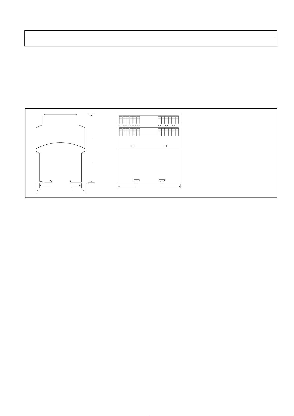
Montage
Das Sicherheitsschaltgerät muss in einen
Schaltschrank mit einer Schutzart von mind.
IP54 eingebaut werden. Zur Befestigung auf
einer Normschiene hat das Gerät ein
Rastelement auf der Rückseite.
Inbetriebnahme
Beachten Sie bei der Inbetriebnahme:
• Nur die Ausgangskontakte 13-14/23-24/
33-34/57-58/67-68) sind Sicherheits-
kontakte. Ausgangskontakt 41-42 ist ein
Hilfskontakt (z. B. für Anzeige).
•Vor die Ausgangskontakte eine
Sicherung (10 A flink oder 6,3 A träge)
schalten, um das Verschweißen der
Kontakte zu verhindern.
• Eingangskreis
Temperatur: +25 °C
Max. Leitungslängen:
- Leiterquerschnitt: 1,5 mm2
DC: 3500 m
• Das Anzugsdrehmoment der Schrauben
auf den Anschlussklemmen darf max.
0,8 Nm betragen.
• Leitungsmaterial aus Kupferdraht mit
einer Temperaturbeständigkeit von
60/75 °C verwenden.
• Angaben im Kapitel "Technische Daten"
unbedingt einhalten.
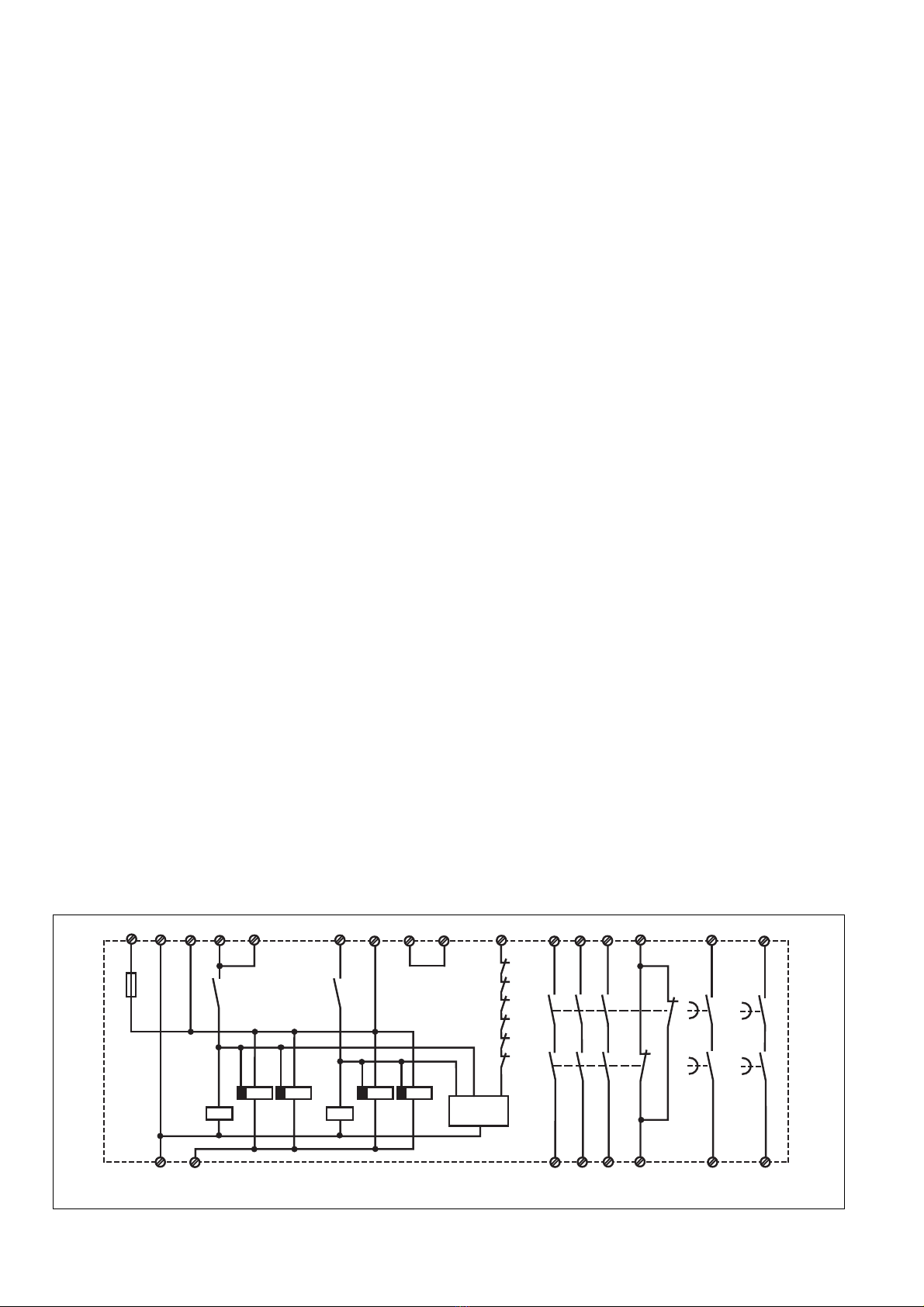
Ablauf:
• Verzögerungszeit t1 für Sicherheitskontakt
57-58 und t2 für Sicherheitskontakt 67-68
mit Hilfe eines Schraubendrehers festle-
gen.
• Betriebsspannung an Klemmen A1 (-) und
A2 (+) anlegen.
• Rückführkreis schließen
Brücke an Y1-Y2 oder externe Schütze
anschließen.
• Aktivierungskreis schließen
- Automatischer Start: S33-S34 brücken.
-
Manueller Start: Taster an S33-S34
anschließen (keine Brücke an S33-S34).
• Eingangskreis schließen
- Einkanalig: S12-S22 brücken. Öffner-
kontakt von Auslöseelement an S11 und
S12 anschließen.
- Zweikanalig: Öffnerkontakt von Auslöse-
element an S11-S12/S11-S22 anschlie-
ßen.
• Reset-Eingang schließen
- ohne Reset-Funktion: Y39-Y40 brücken.
- mit Reset-Funktion: Öffnerkontakt an
Y39-Y40 anschließen.
Operating Modes:
• Single-Channel Operation: Input wiring
according to VDE 0113 and EN 60204, no
redundancy in the input circuit, earth fault
detection in the Emergency-Stop Button
Circuit
• Two-Channel Operation: redundancy in
the input circuit, earth fault detection in the
Emergency-Stop Button Circuit
• Automatic reset: the device is activated as
soon as the input circuit is closed
• Manual reset: the device is only activated
after a reset button is pressed. This
prevents automatic start-up following a
loss/return of supply voltage
• Increase in the number of available
contacts by connection of external
contactors/relays
Installation
The safety relay must be panel (min. IP54)
mounted. There is a notch on the rear of the
unit for DIN rail attachment.
Operation
Please note for operation:
• Only the output contacts 13-14, 23-24, 33-
34, 57-58 and 67-68 are safety contacts.
• Output contact 41-42 is an auxiliary signal
contact (e.g. for a signal lamp).
•A 10 A fast or 6.3 A slow acting fuse
must be connected before the output
contacts, to prevent welding of the
contacts.
• Input Circuit
Temperature: +25 °C
Max. cable lengths:
- Cable: 1.5 mm2
DC: 3500 m
• Tighten terminals to 0,8 Nm.
• Use copper wire that can withstand
60/75 °C.
• Important details in the section „Technical
Data“ should be noted and adhered to.
To operate:
• Adjust the desired delay time t1 of contact
57-58 and t2 of contact 67-68, using a
screwdriver
• Connect the supply voltage leads to
terminals A1 (-) and A2 (+)
• Close the Feedback Control Loop
Y1 - Y2 bridged, or connect the contacts
of external contactors/relays
• Close the Activation Circuit
- Automatic reset: Terminals S33-S34
bridged
- Manual reset: Replace the bridge S33-
S34 with a n/o contact of a pushbutton
• Close the Input Circuit
- Single Channel: Terminals S12-S22
bridged. Connect a n/c contact of the
activating switch to S11-S12
- Two-Channel: Connect n/c contacts of
the activating switch to terminals S11-
S12 and S11-S22
• Close the Reset Circuit
- without reset function: Bridge terminals
Y39-Y40
- with reset function: Replace the bridge
Y39-Y40 with a n/c contact
Montage
Le relais doit être monté dans l'armoire
électrique ayant au min. un indice de
protection IP54. Sa face arrière permet un
montage rapide sur rail DIN.
Mise en oeuvre
Remarques préliminaires:
• Seuls les contacts 13-14/23-24/33-34/57-
58/67-68 sont des contacts de sécurité.
Le contact 41-42 est un contact
d'information.
• Protection des contacts de sortie par
des fusibles (10 A rapides ou 6,3 A
normaux) pour éviter leur soudage.
• Circuit d’entrée
température: +25 °C
longueur maxi. câblage:
- câble: 1,5 mm2
DC: 3500 m
• Le couple de serrage sur les bornes de
racordement ne doit pas dépasser
0,8 Nm.
• Utiliser uniquement des fils de câblage en
cuivre 60/75 °C.
• Respectez les données indiquées dans les
caractéristiques techniques.
Mise en oeuvre:
• Régler la temporisation t1 du contact
57-58 et la temporisation t2 du contact
67-68 à l'aide d'un tournevis.
• Amener la tension d'alimentation aux
bornes A1 (+) et A2 (-)
• Fermer la boucle de retour:
pont entre Y1-Y2 ou câblage des
contacts externes.
• Fermer le circuit de réarmement:
- réarmement automatique: pontage des
bornes S33-S34.
- réarmement manuel: câblage d'un
poussoir sur S33-S34 (pas de
pontage).
• Fermer le circuit d'entrée:
- commande par 1 canal: câblage du
contact à ouverture entre S11 et S12,
pontage de S12-S22
- commande par 2 canaux: câblage des
contacts à ouverture entre S11-S12/
S21-S22.
• Fermer la boucle de Reset:
- sans fonction Reset: pont sur Y39-Y40
- avec fonction Reset: câblage d'un
contact à ouverture sur Y39-Y40.
Mode de fonctionnements:
• commande par 1 canal: conforme aux
prescriptions de la norme EN 60204, pas
de redondance dans le circuit d'entrée.La
mise à la terre du circuit d'entrée est
détectée.
• commande par 2 canaux : circuit d'entrée
redondant, la mise à la terre du circuit
d'entrée est détectée.
• Réarmement automatique: le relais est
activé dès la fermeture du circuit d'entrée.
• Réarmement manuel: le relais n'est activé
qu'après une impulsion sur le poussoir de
réarmement. Un réarmement automatique
du relais après une coupure d'alimentation
est ainsi impossible
• Augmentation du nombre de contacts ou
du pouvoir de coupure par l'utilisation de
contacteurs externes

- 4 -
Die Sicherheitskontakte sind aktiviert und der
Hilfskontakt (41-42) ist geöffnet. Die
Statusanzeigen leuchten. Das Gerät ist
betriebsbereit.
Wird der Eingangskreis geöffnet, öffnen die
Sicherheitskontakte 13-14/23-24/33-34/ und
der Hilfskontakt 41-42 schließt. Die Leucht-
dioden "ch.1" und "ch.2" erlöschen. Der Si-
cherheitskontakt 57-58 öffnet sich nach
Ablauf von t1 und Sicherheitskontakt 67-68
nach Ablauf von t2. Die Leuchtdioden t1 und
t2 erlöschen.
Wieder aktivieren
• Eingangskreis schließen
• Bei manuellem Start zusätzlich Taster
zwischen S33 und S34 betätigen.
Die Statusanzeigen leuchten wieder, die
Sicherheitskontakte sind geschlossen.
Reset-Funktion
Die Reset-Funktion stellt die Verzögerungs-
zeiten t1 und t2 auf 0s. Dazu wird statt einer
Brücke ein Öffnerkontakt zwischen Y39-Y40
geschaltet. Öffnet der Kontakt während
Ablauf der Verzögerungszeit, öffnen die
zeitverzögerten Sicherheitskontakte sofort.
Gerät nur wie in den Abbildungen (Fig.
2-7) beschrieben anschließen!
The safety contacts are activated and the
aux. contact 41-42 is open. The status
indicator LED´s illuminate. The unit is ready
for operation. If the input circuit is opened (E-
Stop Button is pressed or Safety Guard is
opened), safety contacts 13-14, 23-24 and
33-34 are opened immediately and the aux.
contact 41-42 is closed immediately. LED´s
„ch.1“ and „ch.2“ are off. The delay period t1
and t2 is started. The safety contact 57-58 is
opened and LED t1 is no longer illuminated
after delay period t1 has elapsed. The safety
contact 67-68 is opened and LED t2 is no
longer illuminated after delay period t2 has
elapsed.
Reactivation
• Close input circuit
• with manual reset, the button between S33
and S34 must also be pressed.
The status indicators light up again, the
safety contacts are closed.
Reset
This function sets the delay period t1 and t2
to zero. Instead of a bridge, connect a button
with n/c contact to Y39-Y40. If the contact is
opened during the delay period, contacts
57-58 and 67-68 are opened immediately.
The unit must only be connected as
shown in the illustrations (Fig. 2-7)!
S11 S12 S33
S12
Y1
Y2
S34
S22
Y39
Y40
S11 S33
S12
Y1
Y2
S34S22
Y39
Y40
S11
S12 S33
S34S22
S1
S2
Y1
Y2
Y39
Y40
Fig. 2: Eingangskreis einkanalig:
NOT-AUS-Beschaltung; manueller Start/
Single channel input circuit: emergency
stop, manual reset/commande par 1 canal:
poussoir AU, réarmement manuel
Fig. 3: Eingangskreis zweikanalig;
NOT-AUS-Beschaltung; manueller Start/
Two-channel input circuit: emergency stop,
manual reset/commande par 2 canaux:
poussoir AU, réarmement manuel
Fig. 4: Zweikanalige Schutztürsteuerung mit
Funktions- und Anlaufüberprüfung/
Two-channel input circuit: Safety Gate
control with function and start-up test/
commande par 2 canaux: surveillance d'un
protecteur avec test des conditons initiales
S11
S12
S22
Y1
Y2
S33
Start
S34
Y39
Y40
Y39
Y40
K7
Y1
Y2
K6
K9
K6
K7
N
57
23
58
24
K11
67
68
K7
K8 K9
L1
K6 K8 K10
K8
K9
K10
K11
K10
K11
Fig. 5: Zweikanalige Schutztürsteuerung
mit Stellungsüberwachung/Two-channel
input circuit: Safety Guard control with
position monitoring/commande par 2
canaux: surveillance de protecteur avec
contrôle de position
Fig. 6: Öffnerkontakt ermöglicht
Reset-Funktion der Verzöge-
rungszeit/Reset circuit: delay
time reset function/circuit
Reset: permet la mise à 0 des
temporisations
Fig. 7: Verstärkung (Vervielfältigung) der Kontakte
durch externe Schütze/Connection for external
contacts/relays, single-channel/Multiplication des
contacts à l'aide de contacteurs externes
Tür nicht geschlossen/
gate open/
porte ouverte
Tür geschlossen/
gate closed/
porte fermée
betätigtes Element/
switch activated/
élément actionné
Les contacts de sécurité sont fermés et le
contact d'information est ouvert. Les LEDs de
visualisation sont allumées. Le relais est
activé. Si le circuit d'entrée est ouvert, les
contacts de sécurité 13-14/23-24/33-34
s'ouvrent instantanément et le contact d'info
41-42 se ferme. Les LEDs "ch.1" et "ch.2"
s'éteingnent. Le contact de sécurité 57-58
s'ouvre au bout du temps t1. La LED
"t1"s'éteint. Le contact de sécurité 67-68
s'ouvre au bout du temps t2. La LED "t2"
s'éteint.
Remise en route:
• fermer le circuit d'entrée
• en cas de réarmement manuel, appuyer
sur le poussoir S33-S34.
Les affichages d'état s'allument à nouveau.
Les contacts de sécurité sont fermées.
Reset
Cette fonction permet de mettre à 0 les
temporisations t1 et t2. Pour cela un contact
à ouverture est câblé entre les bornes
Y39-Y40 à la place du pont. Si ce contact est
ouvert pendant l'écoulement des
temporisations, les contacts temporisés de
sécurité 57-58 et 67-68 s'ouvrent
instantanément.
Les exemples de branchement (Fig. 2-7)
doivent être respectés!

- 5 -
Fehler - Störungen
• Eine elektronische Sicherung bewirkt das
Öffnen der Ausgangskontakte. Nach
Wegfall der Störungsursache und bei
Einhalten der Betriebsspannung ist das
Gerät nach ca. 1 s wieder betriebsbereit.
• Fehlfunktionen der Kontakte: Bei ver-
schweißten Kontakten ist nach Öffnen des
Eingangskreises keine neue Aktivierung
möglich.
• Nur eine oder keine der Leuchtdioden
leuchtet: Externer Beschaltungsfehler
oder interner Fehler liegt vor.
Faults
• An electronic fuse causes the output
contacts to open. If the fault is removed
and the rated supply voltage is upheld, the
unit is ready for operation after appx. 1
sec.
• Contact failure: If contacts weld, no further
activation will be possible following an
opening of the input circuit.
• Only one or no LED illuminates: an
external wiring fault or an internal fault is
present.
Erreurs- Défaillances
• Un fusible électronique entraîne l'ouverture
des contacts de sorties en cas de court-
circuit. L'appareil est à nouveau prêt à
fonctionner env. 1 sec. après la disparition
du défaut.
• Défaut d'un contact: en cas de collage d'un
contact après ouverture du circuit
d'entrée, un nouvel réarmement est
impossible.
• Seule une ou pas de LED est allumée:
erreur de câblage externe ou défaut
interne du relais.
Technische Daten/Technical Data/Caractéristiques techniques
Betriebsspannung UB/Operating Voltage UB /Tension d'alimentation UB-24 V DC
Spannungstoleranz/Voltage Tolerance/Plage de la tension d’alimentation -15 ... +10 %
Leistungsaufnahme bei UB/Power Consumption/Consommation UBDC: 6,5 W
Restwelligkeit/Residual Ripple/Ondulation résiduelle DC: 160 %
Spannung und Strom an/Voltage, Current at/Tension et courant du
Eingangskreis/Input circuit/circuit d’entrée 24 V DC, 35,0 mA
Startkreis/reset circuit/circuit de réarmement 24 V DC, 100,0 mA
Rückführkreis/feedback loop/boucle de retour 24 V DC, 100,0 mA
Ausgangskontakte/Output Contacts/Contacts de sortie
Unverzögert/Instantaneous/Instantés 3 Sicherheitskontakte/Safety contacts/
Contacts de securitè
1 Hilfskontakt (Ö), auxilliary contact N/C,
contact auxilliaire
Verzögert/Delayed/Temporisés à retombée 2 Sicherheitskontakte/Safety contacts/
Contacts de securitè
Kategorie nach/Category to/Catégorie d'après EN 954-1, EN ISO 13849-1
Unverzögert/Instantaneous/Instantés 4
Verzögert/Delayed /Temporisés à retombée 3
Gebrauchskategorie nach/Utilization category to/Catégorie d’utilisation d'après
Ausgangskontakte unverzögert/Output Contacts instantaneous/Contacts de sortie instantés
EN 60947-4-1
AC1: 240 V Imin: 0,01 A, Imax: 8,0 A, Pmax: 2000 VA
AC1:400 V Imin: 0,01 A, Imax: 5,0 A, Pmax: 2000 VA
DC 1: 24 V Imin: 0,01 A, Imax: 8,0 A, Pmax: 200 W
EN 60947-5-1
AC 15: 230 V Imax: 5,0 A
DC13 (6 Schaltspiele/Min, 6 cycles/min, 6 manoeuvres/min): 24 V Imax: 7,0 A
Ausgangskontakte verzögert/Output Contacts delayed/
Contacts de sortie temporisés à retombée
EN 60947-4-1
AC1: 240 V Imin: 0,01 A, Imax: 4,0 A, Pmax: 1000 VA
DC 1: 24 V Imin: 0,01 A, Imax: 4,0 A, Pmax: 100 W
EN 60947-5-1
AC 15: 230 V Imax: 4,0 A
DC13 (6 Schaltspiele/Min, 6 cycles/min, 6 manoeuvres/min): 24 V Imax: 4,0 A
Kontaktmaterial/Contact material/Matériau contact AgSnO2+ 0,2 µm Au
Kontaktabsicherung extern nach/External Contact Fuse Protection/Protection des contacts
EN 60947-5-1 (IK= 1 kA)
Ausgangskontakte unverzögert/Output Contacts instantaneous/Contacts de sortie instantés
Schmelzsicherung/Blow-out fuse/Fusibles 10 A flink/quick acting/rapide oder /or/ou
6 A träge/slow acting/normeaux
Sicherungsautomat/Safety cut-out/Dijoncteur 24 V AC/DC: 6 A Charakteristik /
Characteristic/Caractéristiques B/C
Ausgangskontakte verzögert/Output Contacts delayed/
Contacts de sortie temporisés à retombée
Schmelzsicherung/Blow-out fuse/Fusibles 6 A flink/quick acting/rapide oder /or/ou
4 A träge/slow acting/normeaux
Sicherungsautomat/Safety cut-out/Dijoncteur 24 V AC/DC: 4 A Charakteristik /
Characteristic/Caractéristiques B/C
Max. Gesamleitungswiderstand Rlmax (Eingangskreis)/Max. total cable resistance Rlmax
(input circuit)/Résistivité de câblage totale max. Rlmax (Circuits d’entrée)
einkanalig/Single-channel/Commande par 1 canal 60 Ohm
zweikanalig ohne Querschlusserkennung/Dual-channel without detection of shorts across
contacts/Commande par 2 canaux sans détection des court-circuits 120 Ohm
zweikanalig mit Querschlusserkennung/Dual-channel with detection of shorts across
contacts/Commande par 2 canaux avec détection des court-circuits 5 Ohm

- 6 -
Es gelten die 2008-07 aktuellen Ausgaben
der Normen
The version of the standards current at
2008-07 shall apply
Se référer à la version des normes en vigeur
au 2008-07.
Einschaltverzögerung/Switch-on delay/Temps d’enclenchement
Automatischer Start/Automatic reset/Réarmement automatique typ. 200 ms, max. 300 ms
Automatischer Start nach Netz-Ein/Automatic reset after Power-ON/ Réarmement
automatique après mise sous tension typ. 200 ms, max. 300 ms
Manueller Start/Manual reset/Réarmement manuel typ. 200 ms, max. 300 ms
Rückfallverzögerung /Delay-on De-Energisation /Temps de retombée
bei NOT-AUS/at E-STOP/en cas d'arrêt d'urgence typ.: 15 ms, max.: 30 ms
bei Netzausfall/with power failure/en cas de coupure d'alimentation typ.: 30 ms, max.: 40 ms
Verzögerungszeit/Delay-on De-Energisation/Temps de retombée tv1
einstellbar/adjustable/réglable 0,1 /0,2/0,3/0,4/0,5/0,6/0,7/0,8/1/1,5/2/3 s
Verzögerungszeit/Delay-on De-Energisation/Temps de retombée tv2
einstellbar/adjustable/réglable 1/2/3/4/5/6/7/8/10/12/15/20 s
Wiederholgenauigkeit/Repetition accuracy/Précision de reproductibilité 2 %
Zeitgenauigkeit/Time accuracy/Précision du temps -15% / +15% +50 ms
Wiederbereitschaftszeit bei max. Schaltfrequenz 1/s/recovery time at max. switching
frequency 1/s/temps de remise en service en cas de fréquence de commutation max. 1/s
nach NOT-AUS/after E-STOP/après l'arrêt d'urgence 50 ms + tv
nach Netzausfall/after power failure/après une coupure d'alimentation 100 ms
Gleichzeitigkeit Kanal 1 und 2/Simultaneity channel 1 and 2/Désynchronisme canal 1 et 2 150 ms
Überbrückung bei Spannungseinbrüchen/Max. supply interruption before
de-energisation/Tenue aux micro-coupures 20 ms
EMV/EMC/CEM
EN 60947-5-1, EN 61000-6-2
Schwingungen nach/Vibration to/Vibrations d'après EN 60068-2-6
Frequenz/Frequency/Fréquences:10-55 Hz
Amplitude/Amplitude/Amplitude: 0,35 mm
Klimabeanspruchung/Climate Suitability/Conditions climatiques EN 60068-2-78
Luft- und Kriechstrecken nach/Airgap Creepage to/Cheminement et claquage
d'après EN 60947-1
Verschmutzungsgrad/Pollution degree/Niveau d'encrassement 2
Bemessungsisolationsspannung/Rated insulation voltage/Tension assignée d'isolement 400 V
Bemessungsstoßspannungsfestigkeit/Rated impulse withstand voltage/Tension assignée de
tenue aux chocs 4 kV
Betriebstemperatur/Operating Temperature/Température d’utilisation -10 - 55 °C
Lagertemperatur/Storage Temperature/Température de stockage -40 - 85 °C
Schutzart/Protection/Indice de protection
Einbauraum (z. B. Schaltschrank)/Mounting (eg. panel)/Lieu d'implantation (ex. armoire) IP54
Gehäuse/Housing/Boîtier IP40
Klemmenbereich/Terminals/Bornes IP20
Gehäusematerial/Housing material/Matériau du boîtier
Gehäuse/Housing/Boîtier PPO UL 94 V0
Front/Front panel/Face avant ABS UL 94 V0
Querschnitt des Außenleiters/Cable cross section/ Capacité de raccordement
1 Leiter, flexibel/1 core, flexible/1 conducteur souple 0,20 - 4,00 mm2/24-10 AWG
2 Leiter gleichen Querschnitts, flexibel mit Aderendhülse, ohne Kunststoffhülse/
2 core, same cross section flexible with crimp connectors, without insulating sleeve/
2 conducteurs de même diamètre souple avec embout, sans chapeau plastique 0,20 - 2,50 mm2/24-14 AWG
ohne Aderendhülse oder mit TWIN-Aderendhülse/without crimp connectors or with TWIN
crimp connectors/souple sans embout ou avec embout TWIN 0,20 - 2,50 mm2/24-14 AWG
Anzugsdrehmoment Schrauben (auf Anschlussklemmen)/Torque setting for connection terminal
screws/Couple de serrage (bornier) 0,60 Nm
Abmessungen H x B x T/Dimensions H x W x D /Dimensions H x P x L 87 mm x 112,5 mm x 121 mm
Einbaulage/Fitting Position/Position de travail beliebig; any; indifférente
Gewicht/Weight/Poids 600 g

- 7 -
Konventioneller thermischer Strom bei gleichzeitiger Belastung mehrerer Kontakte/Conventional thermal current while
loading several contacts/Courant thermique conventionnel en cas de charge sur plusieurs contacts (AC1, DC1)
Anzahl der Kontakte/number of contacts/nombre des contacts 54321
Ith (A) pro Kontakt bei Versorgungsspannung DC/per contact
with operating voltage DC/par contact pour tension d’alimentation DC 4,5 5,0 5,5 6,8 8,0
To prevent failure of the unit, all output
contacts should be fused adequately. With
capacative loads, possible current peaks are
to be avoided. With DC contactors/relays
use suitable spark suppression to ensure
extended life of the contactors/relays.
Um ein Versagen der Geräte zu verhindern,
an allen Ausgangskontakten für eine aus-
reichende Funkenlöschung sorgen. Bei
kapazitiven Lasten sind eventuell auftretende
Stromspitzen zu beachten. Bei DC-Schützen
Freilaufdioden zur Funkenlöschung einset-
zen, um die Lebendauer der Schütze zu
erhöhen.
Prévoir un dispositif d’extinction d’arc sur les
contacts de sortie pour éviter un éventuel
disfonctionnement du relais.
Tenir compte des pointes d’intensité en cas
de charge capacitive. Equiper les
contacteurs DC de diodes de roue libre .
Abmessungen in mm (")/Dimensions in mm (")/Dimensions en mm (")
112,5 (4.41")
121 (4.76")
75 (2.95")
87 (3.42")

- 8 -
A
Pilz Ges.m.b.H., ✆01 7986263-0, Fax: 01 7986264
AUS
Pilz Australia, ✆03 95446300, Fax: 03 95446311
B L
Pilz Belgium, ✆09 3217570,
Fax: 09 3217571
BR
Pilz do Brasil, ✆11 4337-1241, Fax: 11 4337-1242
CH
Pilz lndustrieelektronik GmbH, ✆062 88979-30, Fax: 062 88979-40
DK
Pilz Skandinavien K/S, ✆74436332, Fax: 74436342
E
Pilz lndustrieelektronik S.L., ✆938497433, Fax: 938497544
F
Pilz France Electronic,
✆03 88104000, Fax: 03 88108000
FIN
Pilz Skandinavien K/S, ✆09 27093700, Fax: 09 27093709
GB
Pilz Automation Technology, ✆01536 460766,
Fax: 01536 460866
I
Pilz ltalia Srl, ✆031 789511, Fax: 031 789555
IRL
Pilz Ireland Industrial Automation, ✆021 4346535, Fax: 021 4804994
J
Pilz Japan Co., Ltd., ✆045 471-2281, Fax: 045 471-2283
MEX
Pilz de Mexico, S. de R.L. de C.V., ✆55 5572 1300, Fax: 55 5572 4194
NL
Pilz Nederland, ✆0347 320477, Fax: 0347 320485
NZ
Pilz New Zealand, ✆09- 6345-350, Fax: 09-6345-352
P
Pilz Industrieelektronik S.L.,
✆229407594, Fax: 229407595
PRC
Pilz China Representative Office, ✆021 62494658, Fax: 021 62491300
ROK
Pilz Korea, ✆031 8159541,
Fax: 031 8159542
SE
Pilz Skandinavien K/S, ✆0300 13990, Fax: 0300 30740
TR
Pilz Elektronik Güvenlik Ürünleri ve Hizmetleri Tic. Ltd. ¸Sti.,
✆0224 2360180, Fax: 0224 2360184
USA
Pilz Automation Safety L.P., ✆734 354-0272, Fax: 734 354-3355
www
www.pilz.com
D
Pilz GmbH & Co. KG, Sichere Automation, Felix-Wankel-Straße 2, 73760 Ostfildern, Deutschland, ✆+49 711 3409-0, Fax: +49 711 3409-133,
E-Mail: [email protected]
18 604-02-2008-08 Printed in Germany
Other manuals for PNOZ 2VJ
1
Table of contents
Other Pilz Relay manuals

Pilz
Pilz PNOZ Ex User manual

Pilz
Pilz PNOZ X Series User manual

Pilz
Pilz PNOZ X9P AC/DC User manual

Pilz
Pilz PU3Z User manual

Pilz
Pilz PNOZ s7 Series User manual

Pilz
Pilz P2HZ X1 User manual

Pilz
Pilz PNOZ X3P User manual

Pilz
Pilz PZW Series User manual

Pilz
Pilz PNOZ X2.7P User manual

Pilz
Pilz PNOZ XV3.1 User manual

Pilz
Pilz PNOZ XV3 User manual

Pilz
Pilz PNOZ X3 User manual

Pilz
Pilz PNOZ X2.4V User manual

Pilz
Pilz PNOZ pps1p User manual

Pilz
Pilz PNOZ e1vp 10 User manual

Pilz
Pilz PZE X4VP8 User manual

Pilz
Pilz PNOZ ms2p HTL User manual

Pilz
Pilz PZE X4V8 User manual

Pilz
Pilz PNOZ mc0p User manual

Pilz
Pilz PZE X5 User manual