- 1 -
Sicherheitsbestimmungen
•
Das Gerät darf nur von Personen
installiert und in Betrieb genommen
werden, die mit dieser Betriebsanleitung
und den geltenden Vorschriften über
Arbeitssicherheit und Unfallverhütung
vertraut sind. Beachten Sie die VDE-
sowie die örtlichen Vorschriften, insbeson-
dere hinsichtlich der Schutzmaßnahmen.
• Beim Transport, bei der Lagerung und im
Betrieb die Bedingungen nach EN 60068-
2-6 einhalten (s. techn. Daten).
• Durch Öffnen des Gehäuses oder
eigenmächtige Umbauten erlischt die
Gewährleistung.
• Montieren Sie das Gerät in einen
Schaltschrank; Staub und Feuchtigkeit
können sonst zu Beeinträchtigungen der
Funktionen führen.
• Sorgen Sie an allen Ausgangskontakten
bei kapazitiven und induktiven Lasten für
eine ausreichende Schutzbeschaltung.
Bestimmungsgemäße Verwendung
Der Kontaktblock PZE 9 dient als Erweite-
rungsgerät zur Kontaktverstärkung und
Kontaktvervielfältigung.
Das Gerät ist bestimmt für den Einsatz in
• Anwendungsschaltungen mit NOT-AUS-
Schaltgeräten, Schutztürwächtern und
Zweihandbedienungsrelais
• Sicherheitsstromkreisen nach
VDE 0113-1 und EN 60204-1
Das Gerät darf nur mit Grundgeräten ver-
wendet werden, die einen Rückführkreis
besitzen.
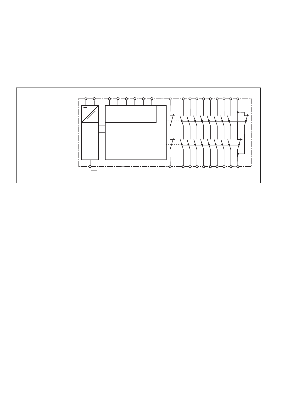
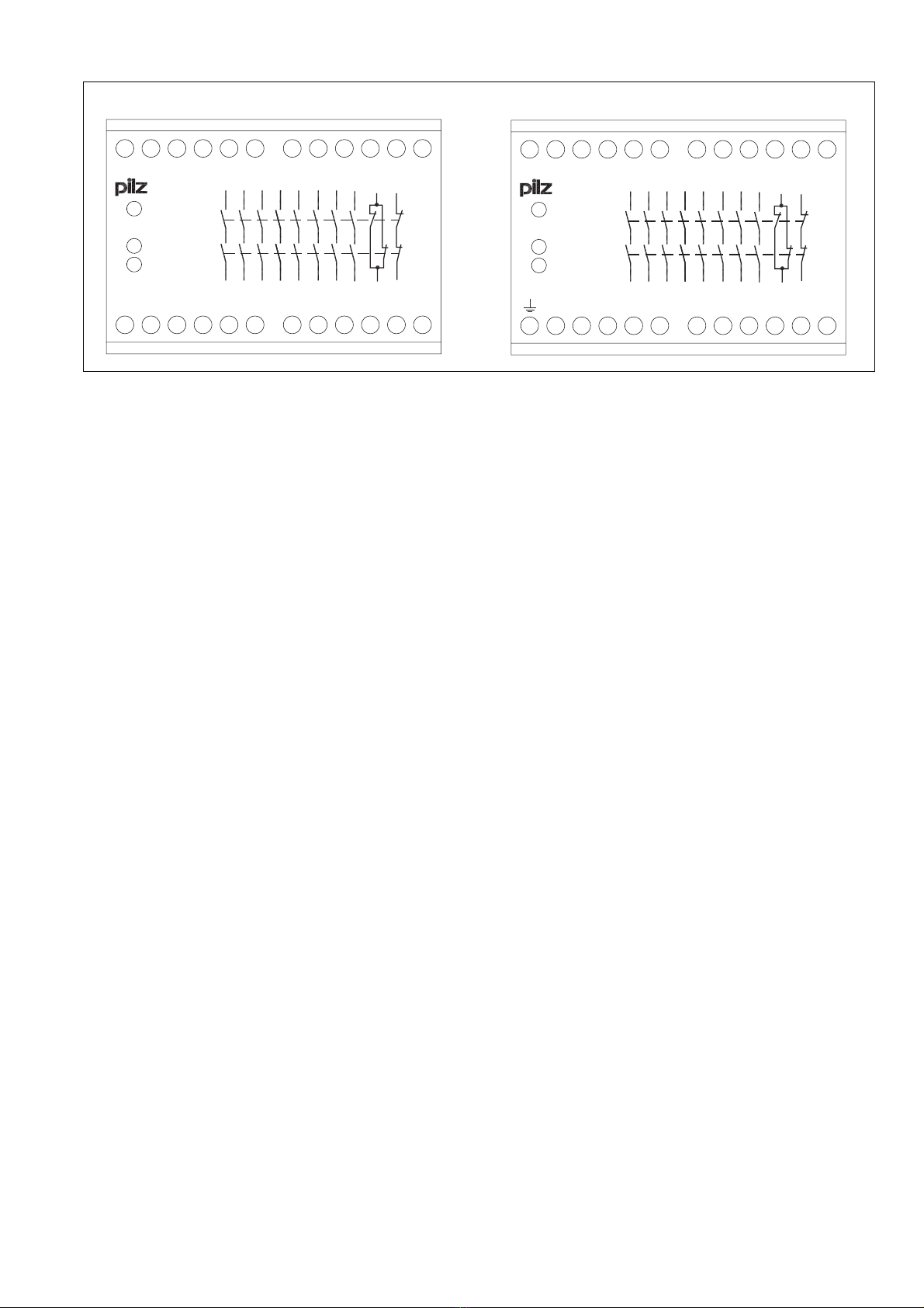
Gerätebeschreibung
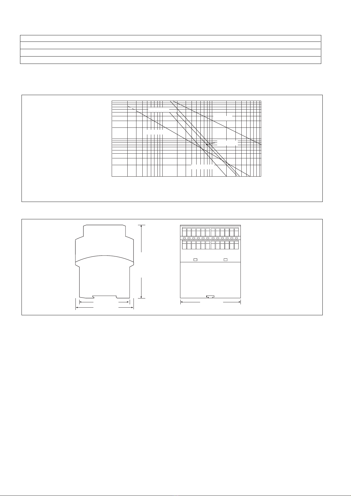
Der Kontaktblock ist in einem P-93-
Gehäuse untergebracht. Es stehen ver-
schiedene Varianten für den Betrieb mit
Wechselspannung und eine Variante für
den Betrieb mit Gleichspannung zur
Verfügung.
Merkmale:
• Relaisausgänge:
8 Sicherheitskontakte (S), zwangsgeführt
1 Hilfskontakt (Ö), zwangsgeführt
• LED als Versorgungsspannungsanzeige
• LEDs als Schaltzustandsanzeige
• Anschluß für Rückführkreis
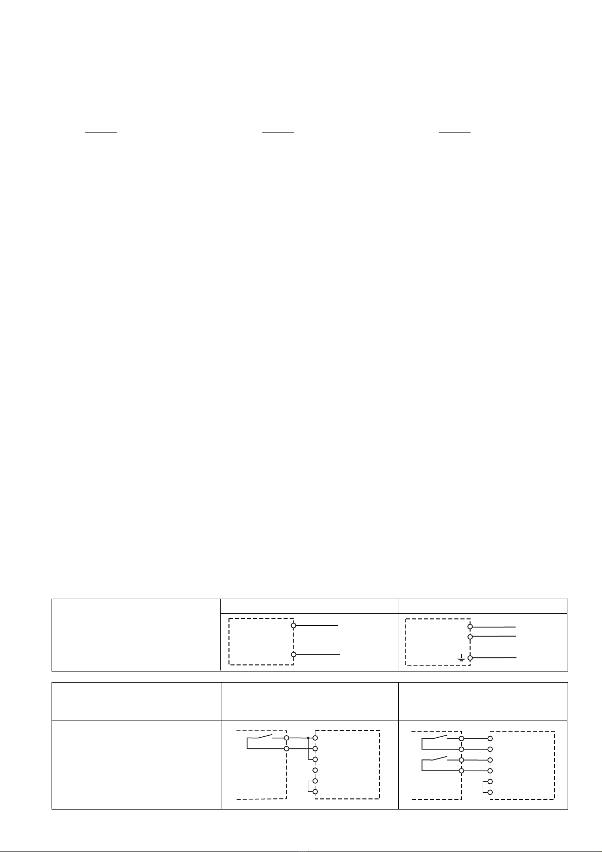
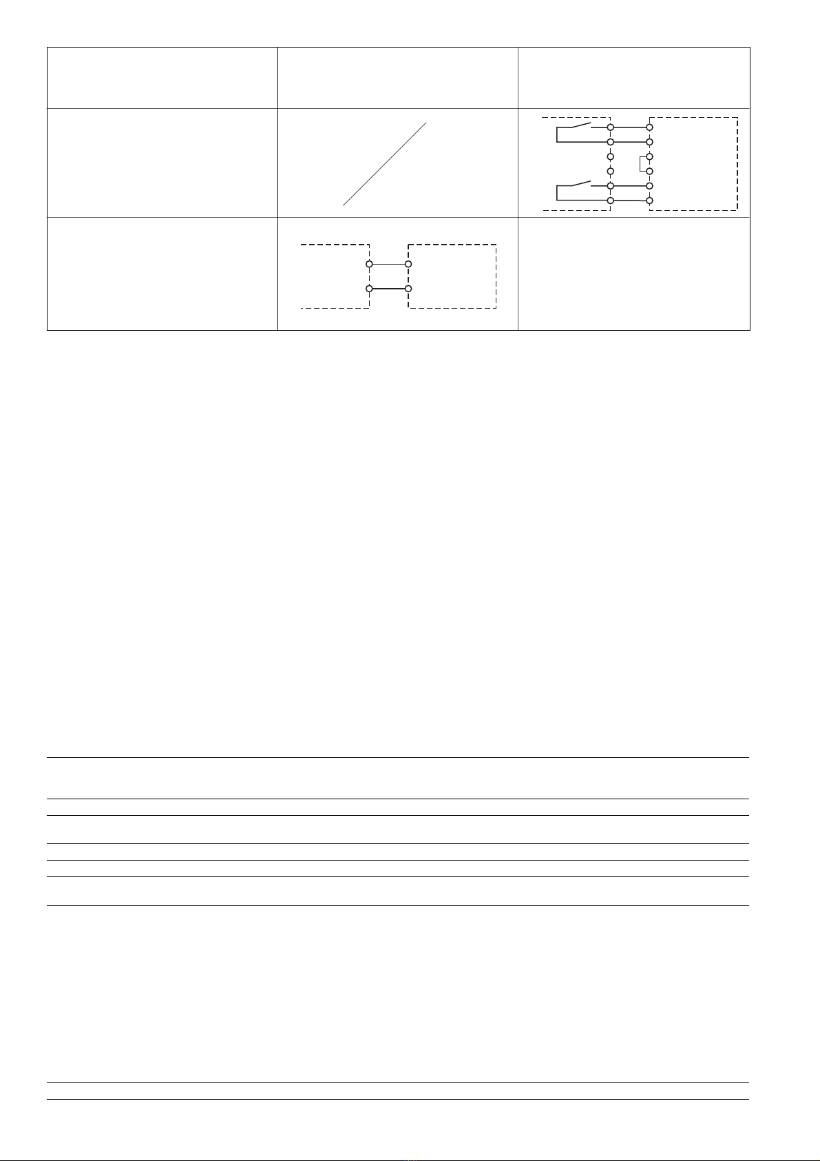
• einkanalige Ansteuerung ohne Quer-
schlußerkennung
• zweikanalige Ansteuerung mit oder ohne
Querschlußerkennung
Die Sicherheitseinrichtung bleibt auch
wirksam bei:
• Spannungsausfall
• Ausfall eines Bauteils
• Spulendefekt
• Leiterbruch
• Erdschluß
Funktionsbeschreibung
Der Kontaktblock PZE 9 ist ein Zusatzgerät
und dient der Erweiterung eines Sicherheits-
stromkreises. Der Kontaktblock wird von
Safety Regulations
• The unit may only be installed and
operated by personnel who are familiar
with both these instructions and the
current regulations for safety at work and
accident prevention. Follow local
regulations especially as regards
preventative measures.
• Transport, storage and operating
conditions should all conform to EN
60068-2-6.
• Any guarantee is void following opening of
the housing or unauthorised modifications.
• The unit should be panel mounted,
otherwise dampness or dust could lead to
functional impairment.
• Adequate fuse protection must be
provided on all output contacts with
capacitive and inductive loads.
Typical Applications
The contact block PZE 9 is an expander
module used to provide additional contacts.
The unit is for use in
• Applications together with Emergency
Stop Relays, Safety Gate Monitors and
Two-Hand Controls
• Safety circuits according to VDE 0113-1
and EN 60204-1
The unit may only be used together with a
base unit which has a feedback control loop.
Description
The Contact Block is enclosed in a P-93
housing. There are different versions
available for AC operation and one for DC
operation.
Features:
• Relay outputs:
8 safety contacts (n/o), positive-guided
1 auxilliary contact (n/c), positive-guided.
• LED Display for Operating Voltage
• LED's for switching positions of all output
relays
• Connections for a feedback control loop
• Single channel operation without short-
circuit recognition
• Two channel operation with or without
short-circuit recognition
The safety function remains effective in the
following cases:
• Power supply failure
• Component failure
• Coil defect in a relay
• Cable break
• Earth fault
Function Description
The Contact block PZE 9 is an add-on unit
for expansion of a safety circuit. The
Contact block is controlled by a base unit
(e.g. E-Stop Relay).
Conseils préliminaires
• La mise en oeuvre de l'appareil doit être
effectuée par une personne spécialisée
en installations électriques, en tenant
compte des prescriptions des différentes
normes applicables (NF, EN, VDE..),
notamment au niveau des risques
encourus en cas de défaillance de
l'équipement électrique.
• Respecter les exigences de la norme
EN 60068-2-6 lors du transport, du
stockage et de l'utilisation de l'appareil.
•
Toutes interventions sur le boîtier
(ouverture du relais, échange ou
modification de composants, soudure etc..)
faites par l'utilisateur annulent la garantie.
• Montez l'appareil dans une armoire
électrique à l'abri de l'humidité et de la
poussière.
• Assurez-vous du pouvoir de coupure des
contacts de sortie en cas de charges
inductives ou capacitives.
Domaines d'utilisation
Le relais PZE 9 est un bloc d'extension qui
permet d'augmenter le nombre et le pouvoir
de coupure des contacts de sécurité.
Le PZE 9 peut être utilisé avec :
• les relais d'arrêt d'urgence, les relais de
surveillance protecteurs et les
commandes bimanuelles.
• dans les circuits de sécurité d'après les
normes VDE 0113-1 et EN 60204-1
Le PZE 9 ne peut être piloté que par des
relais de sécurité ayant une boucle de
retour.
Description de l'appareil
Inséré dans un boîtier P-93, le relais PZE 9
est disponible en différentes versions pour
les tensions d’alimentation alternatives et
une version en alimentation continue (24
VDC).
Particularités :
• Contacts de sortie :
8 contacts à fermeture de sécurité et 1
contact à ouverture, par contacts liés
• LED d'indication présence tension.
• LEDs de visualisation des relais internes
• Bornes pour boucle de retour
• Commande par 1 canaux sans détection
des courts-circuits
• Commande par 2 canaux avec ou sans
détection des courts-circuits
La sécurité est garantie, même dans les cas
suivants :
• Défaillance tension
• Défaillance d'un composant
• Défaillance bobine
• Défaut soudure
• Défaut de masse
Description du fonctionnement
Le relais PZE 9 est un bloc d'extension qui
permet d'augmenter le nombre des
contacts de sécurité. Le PZE 9 est piloté par
un bloc logique de base (par ex. relais
18683-03
PZE 9
4D Betriebsanleitung
4GB Operating instructions
4F Manuel d'utilisation