Sicherheitsbestimmungen
• Das Gerät darf nur von Personen
installiert und in Betrieb genommen
werden, die mit dieser Betriebsanleitung
und den geltenden Vorschriften über
Arbeitssicherheit und Unfallverhütung
vertraut sind. Beachten Sie die VDE-
sowie die örtlichen Vorschriften, insbeson-
dere hinsichtlich der Schutzmaßnahmen.
• Beim Transport, bei der Lagerung und im
Betrieb die Bedingungen nach IEC 68-2-6
einhalten (s. techn. Daten).
• Durch Öffnen des Gehäuses oder eigen-
mächtige Umbauten erlischt die Gewähr-
leistung.
• Montieren Sie das Gerät in einen Schalt-
schrank; Staub und Feuchtigkeit können
sonst zu Beeinträchtigungen der Funktio-
nen führen.
• Sorgen Sie an allen Ausgangskontakten
bei kapazitiven und induktiven Lasten für
eine ausreichende Schutzbeschaltung.
Be
stimmungsgemäße Verwendung
Die Spannungüberwachungsrelais ZUZ und
ZUZ S dienen als Einrichtung zur Überwa-
chung von einphasigen Netzen.
Sie sind bestimmt für den Einsatz als
• Schwellwertglied für Steuerungen
• Überwachungseinrichtung für Betriebs-
spannungen
• Steuerglied für spannungsabhängige
Steuerungen
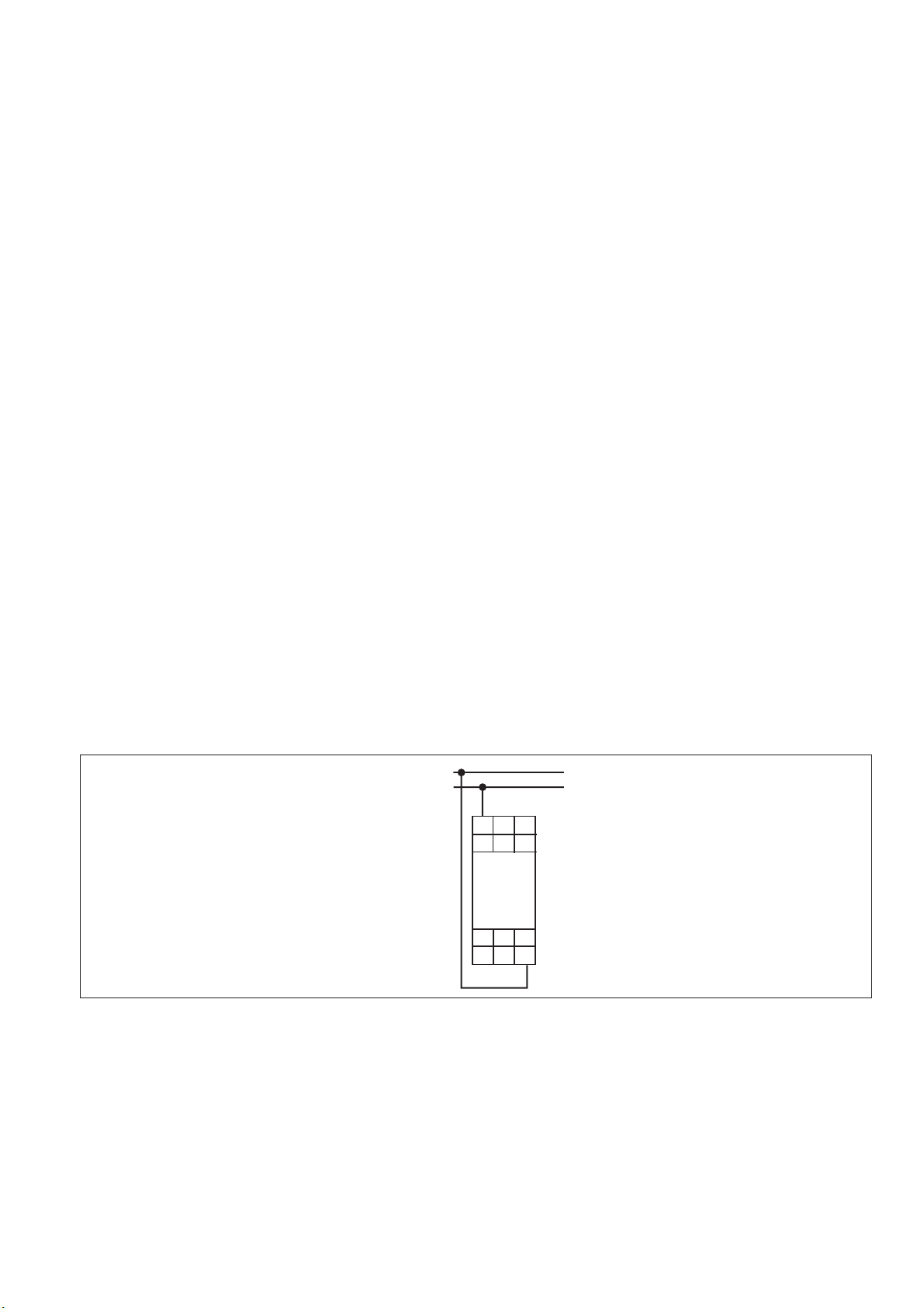
Gerätebeschreibung
Die Spannungsüberwachungsrelais sind in
einem S-95-Gehäuse untergebracht. Als
Betriebsspannung sind beim ZUZ drei Wech-
selspannungen und eine Gleichspannung
einstellbar, beim ZUZ S können 4 Sonder-
spannungen (AC) gewählt werden.
Merkmale:
• Relaisausgänge:
2 Hilfskontakte (U)
• 4 Betriebsspannungen mit Drehschalter ein-
stellbar
• Meßspannung dient als Betriebsspannung
• Einstellmöglichkeiten
- Ansprechwert Unterspannung
Umin: 75 - 100 % UB
- Ansprechwert Überspannung
Umax: 100 - 120 % UB
• LED-Anzeige für Betriebsspannung
• LED-Anzeige für Schaltzustand des Relais
Das ZUZ und ZUZ S arbeiten nach dem
Ruhestromprinzip, d. h. die Geräte sind für
Sicherheitsanwendungen nur mit Einschrän-
kung geeignet.
Conseils préliminaires
• La mise en oeuvre de l’appareil doit être
effectuée par une personne spécialisée en
installations électriques, en tenant compte
des prescriptions des différentes normes
applicables (NF, EN, VDE..), notamment
au niveau des risques encourus en cas de
défaillance de l’équipement électrique.
• Respecter les exigences de la norme
IEC 68-2-6 lors du transport, du stockage
et de l’utilisation de l’appareil.
• Toutes interventions sur le boîtier
(ouverture du relais, échange ou
modification de composants, soudure
etc..) faites par l’utilisateur annulent la
garantie.
• Montez l’appareil dans une armoire
électrique à l’abri de l’humidité et de la
poussière.
• Assurez-vous du pouvoir de coupure des
contacts de sortie en cas de charges
inductives ou capacitives.
Domaines d’utilisation
Les relais de tension ZUZ et ZUZ S
permettent de surveiller des tensions
monophasées.
Le ZUZ/ZUZ S peut être utilisé comme :
• relais de tension pour les système de
commande
• relais de contrôle pour les tensions
d'alimentation
• relais de commande pour les systèmes
de régulation
Description de l’appareil
Les relais de tensions sont insérés dans un
boîtier étroit S-95. Le ZUZ dispose de 3
tensions d'alimentations alternatives et d'une
tension continue sélectionnables par
commutateur. Le ZUZ S dispose de 4
tensions d'alimentation spéciales en AC.
Particularités :
• Contacts de sortie :
2 inverseurs (OF)
• 4 tensions d'alimentation sélectionnables
par commutateur
• La tension mesurée sert également de
tension d'alimentation
• Réglages possibles :
- seuil mini (sous-tension)
Umin: 75-100 % UB
- seuil maxi (sur-tension)
Umax: 100-120 % UB
• LED de visualisation présence tension
• LED de visualisation état du relais
Le ZUZ et ZUZ S indique un défaut par
retombée du relais de sortie. Son utilisation
dans des circuits de sécurité n'est possible
que dans certaines limites.
Safety Regulations
• The unit may only be installed and
operated by personnel who are familiar
with both these instructions and the
current regulations for safety at work and
accident prevention. Follow CEN and
local regulations especially as regards
preventive measures
• Transport, storage and operating
conditions should all conform to IEC 68-2-
6 (see Technical Data)
• Any guarantee is void following opening
the housing or unauthorised modifications
• The unit should be panel mounted,
otherwise dampness or dust could lead to
a malfunction of the unit
• Adequate protection must be provided on
all output contacts with capacitive and
inductive loads.
Authorised Applications
The relays ZUZ and ZUZ S are for
monitoring AC and DC voltage levels in
single phase networks. They are for use as
• In-line connected voltage threshold relays
• Monitoring devices for operating voltages
• Control elements for voltage dependent
control systems.
Description
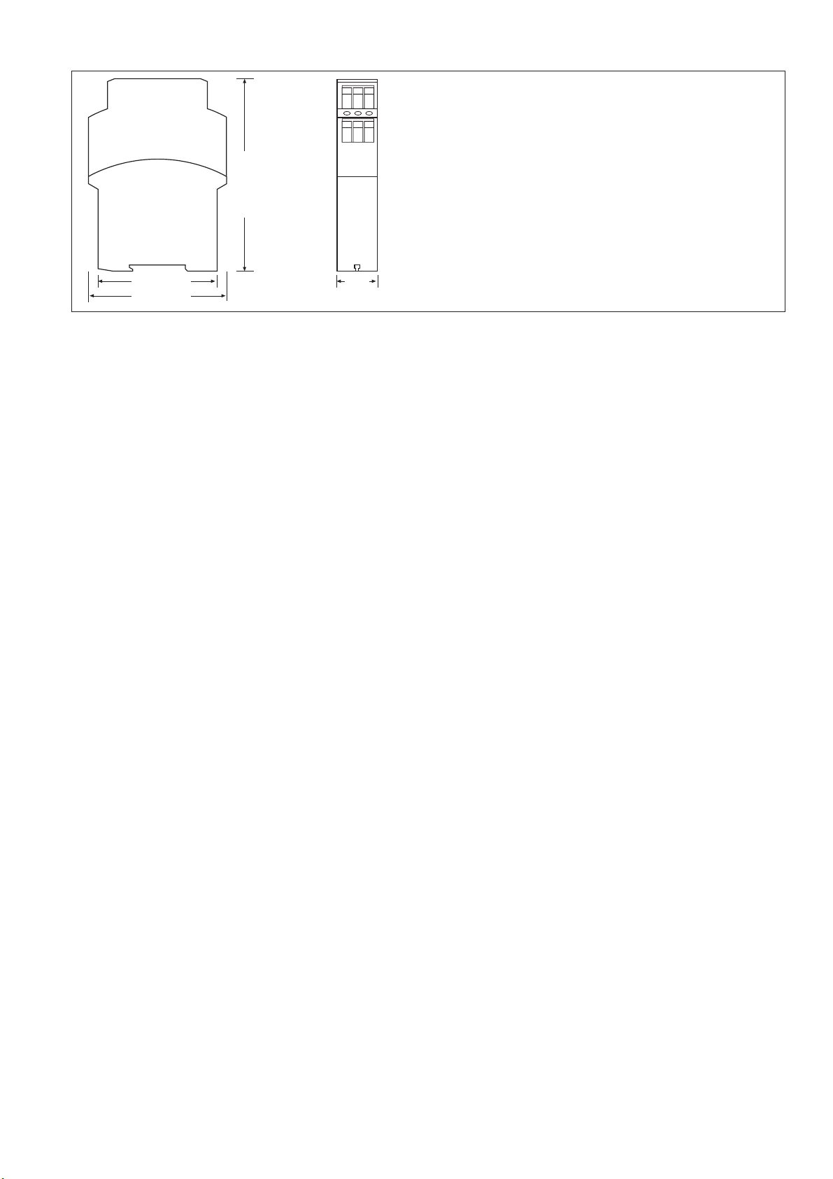
The relays are enclosed in a S-95, 22.5 mm
housing. The ZUZ has 3 selectable AC
voltages and 1 DC voltage available, and on
the ZUZ S, 4 selectable AC operating
voltages are available
Features:
• Relay outputs:
2 auxiliary C/O contacts
• 4 operating voltages, selectable by a
rotary switch
• Measuring voltage also serves as
operating voltage UB= UM
• Adjustable setting range
- Response value under voltage
Umin: 75-100%
- Response value over voltage
Umax: 100-120%
• LED “POWER” status indication for
operating voltage
• LED “FAULT” status indication for output
relay.
The ZUZ and ZUZ S operate in normally de-
energised mode: therefore the unit has
limited use for safety applications.
19391-3FR-03
ZUZ/ZUZ S
Betriebsanleitung
Operating Instructions
Notice d'utilisation