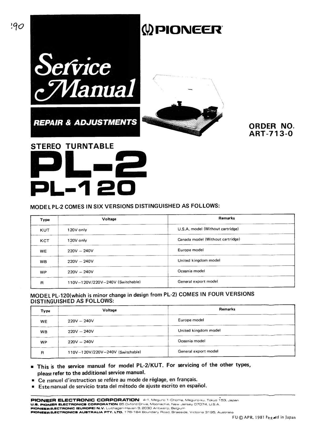
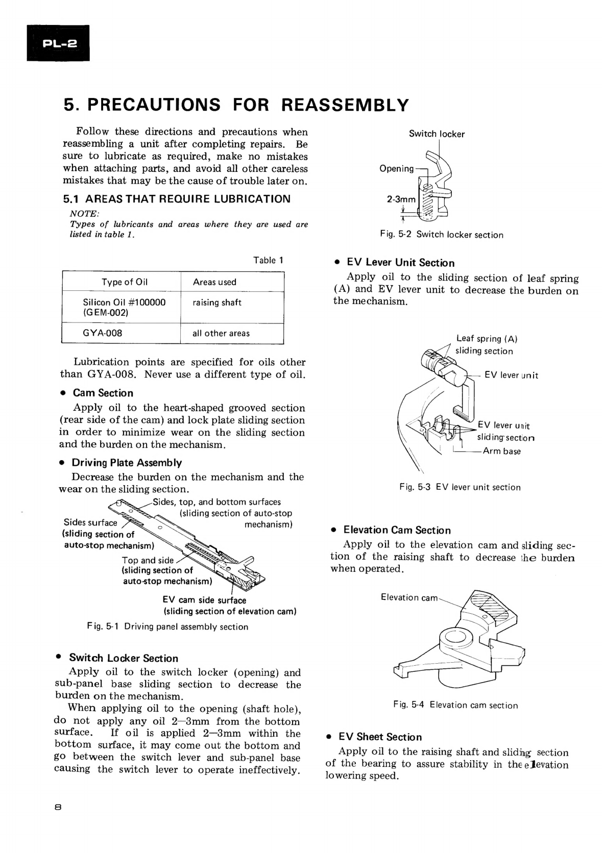
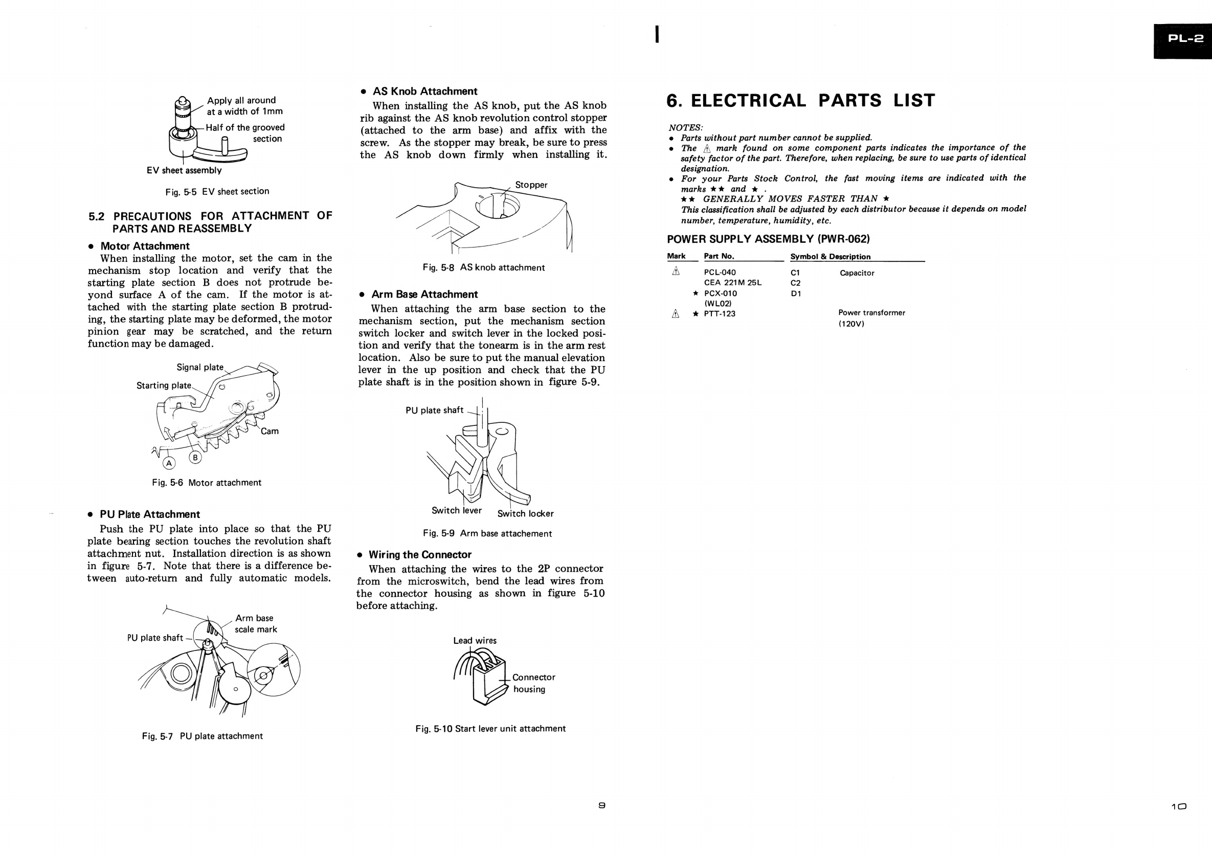
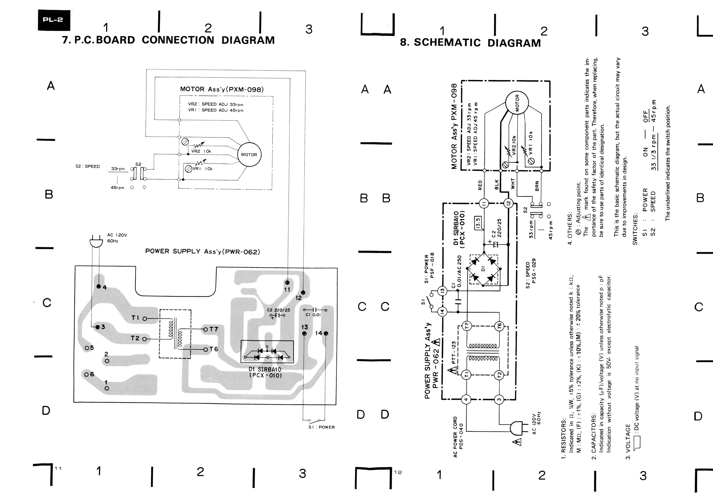
Pioneer PL-2 User manual
Other Pioneer Turntable manuals

Pioneer
Pioneer PL-990 User manual

Pioneer
Pioneer PL-4 User manual

Pioneer
Pioneer DEH-P960MP/XN/UC User manual

Pioneer
Pioneer PL-L1000 User manual

Pioneer
Pioneer PL-55X User manual

Pioneer
Pioneer PL-470 User manual

Pioneer
Pioneer PL-115D User manual

Pioneer
Pioneer PL-50 User manual

Pioneer
Pioneer PL-X420 User manual

Pioneer
Pioneer PL-A45 User manual

Pioneer
Pioneer PL-J2500 User manual

Pioneer
Pioneer PL-44F User manual

Pioneer
Pioneer PL-L70 User manual

Pioneer
Pioneer LC-V4300C User manual

Pioneer
Pioneer pl-x50 User manual

Pioneer
Pioneer PL-570 User manual

Pioneer
Pioneer PL-12D User manual

Pioneer
Pioneer PL-51 User manual

Pioneer
Pioneer PL-112D User manual

Pioneer
Pioneer PL-520 User manual