manuals.online logo
Brands
  1. Home
  2. •
  3. Brands
  4. •
  5. Pioneer
  6. •
  7. Turntable
  8. •
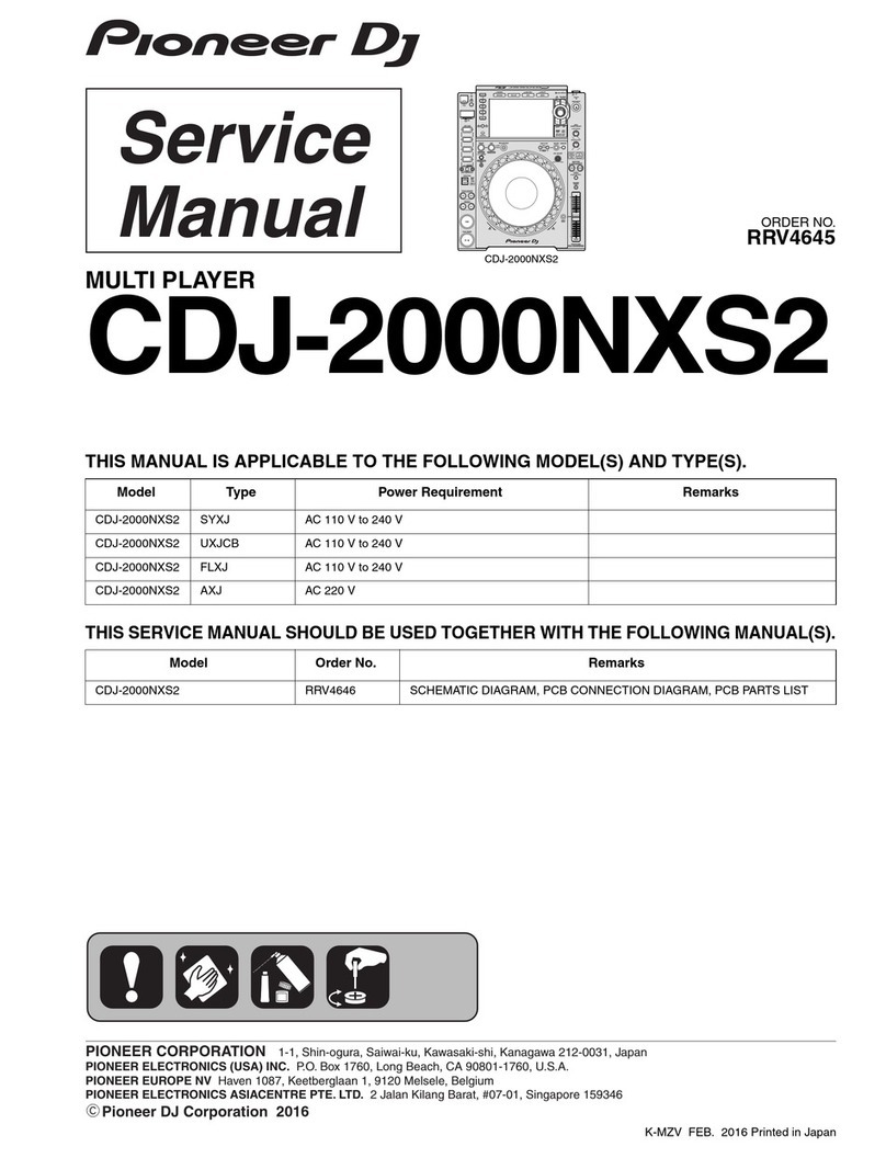
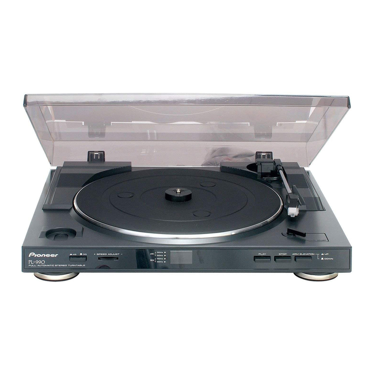
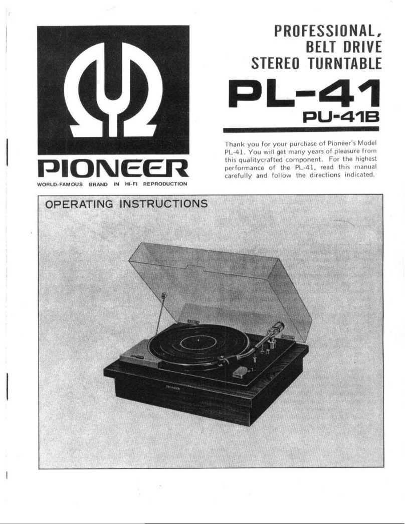
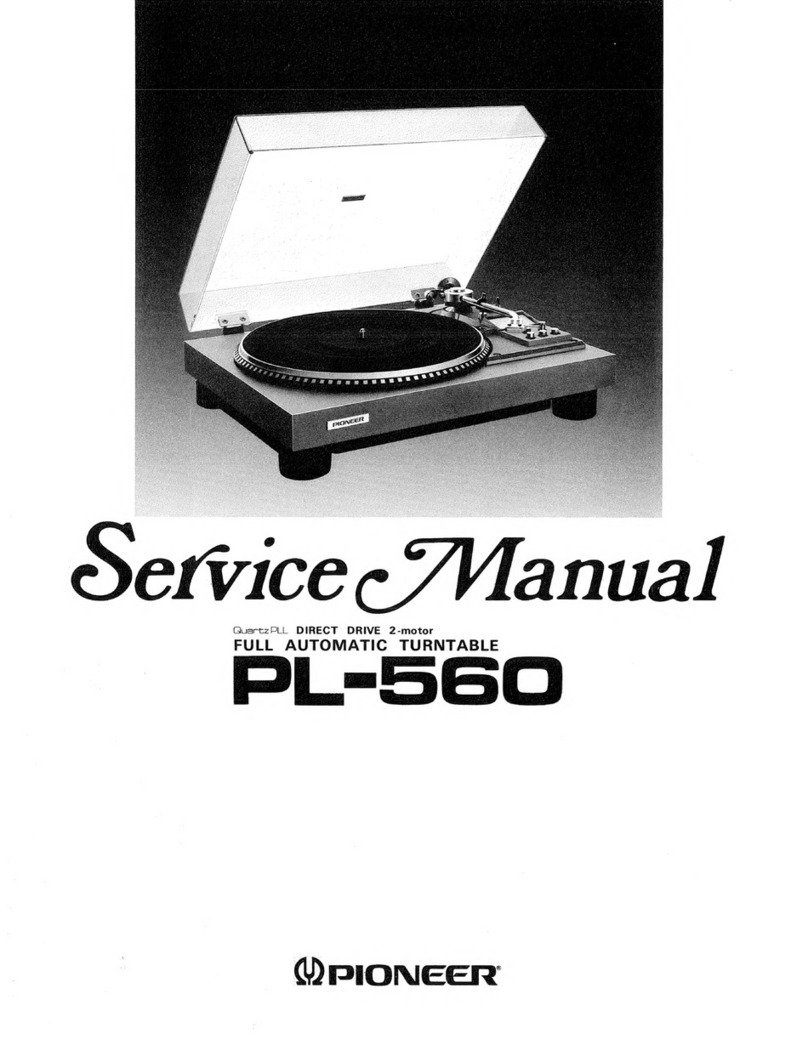
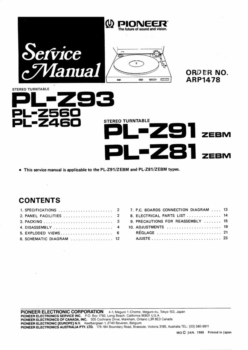
  9. Pioneer PL-Z93 User manual

Pioneer PL-Z93 User manual

YY)
PIONEER’
The
future
of
sound
and
vision.
Service
c/Vanual
iors
STEREO
TURNTABLE
L=-293
PL=Z560
PL-Z2Z460
PL-Z93,
PL-Z560
AND
PL-Z460
HAVE
FOLLOWING
VERSIONS:
Applicable
model
Type
Power
requirement
Destination
PL-Z93
PL-2560
PL-Z460
Australia
European
continent
DC
power
supp!
fzm
|
o
[|
o
|
o
|
:
re
ppv!
and
United
Kingdom
@Refer
to
the
service
manual
ARP1478,
PL-Z91/ZEBM
type.
e
This
manual
is
applicable
to
the
PL-Z93/ZEBM,
ZUC,
PL-Z560/ZEBM
and
PL-Z460/ZEBM
types.
e
As
to
the
system
composition
and
operating
instructions
refer
to
following
service
manual.
PL-Z560,
PL-Z2460
S-777D/S-555D
ARP1930
|
PL-293
po
osa
|
ARP1937
PL-Z2560,
PL-Z460
$-999D
APR1929
|
PL-Z93
$-115CDT
ARP1938
|
PL-293
|
sss
ARP1935
PL-z93
$-115CDM
ARP1939
©
PIONEER
ELECTRONIC
CORPORATION
1989
MA
DEC.
1989
Printed
in
Japan
PL-Z93,
PL-Z560,
PL-Z460
NOTES:
e
Parts
without
part
number
cannot
be
supplied.
©
The
&\
mark
found
on
some
component
parts
indicates
the
importance
of
the
safety
factor
of
the
part.
Therefore,
when
replacing,
be
sure
to
use
parts
of
identical
designa-
tion.
©
Parts
marked
by
“®”
are
not
always
kept
in
stock.
Their
delivery
time
may
be
longer
than
usual
or
they
may
be
unavailable.
The
PL-Z93/ZEBM,
ZUC,
PL-Z560/ZEBM
and
PL-Z460/ZEBM
types
are
the
same
as
the
PL-Z91/ZEBM
type
with
the
exception
of
the
following
sections.
Part
No.
Symbol
&
Description
Sub-panel
assembly
Non
supply
Non
supply
Non
supply
Non
supply
Non
supply
Nameplate
]
we
ee
ee
AAM1002
AAM1002
Speed
button
PAC1226
“PAC1226
PAC1436
PAC1226
PAC1226
EV
button
PAC1227
PAC1227
PAC1437
PAC1227,
#£|
.....
S/S
button
PAC1228)
|
.....
|
ues
PAC1468
|
.....
Cutbutton
~=
|
....,
PAC1467
PAC1469—ss|_—(a....
PAC1467
Front
name
plate
PAM1392
PAM1395
PAM1394
PAM1393
Frontname
plate
assembly
|
.....
|
|
.....
|
weeee
:
PEA1033
PEA1032
Insulator
PEB1105
PEB1105
Insulator
assembly
|
wee
|
eee
ee
PXA1196
PLX1196
Cutrod
=
|
.....
|
Nonsupply
=|
Nonsupply
|
.....
Non
supply
Size
rod
Non
supply
|
.....
|
.....
Nonsupply
|
.....
S/S
rod
Nonsupply
|
.....
|
.....
Nonsupply
|.
.....
Protector
(R)
PHA1045
PHA1045
PHA1045
PHA1082
PHA1082
Protector
(L)
PHA1046
PHA1046 PHA1046
PHA1083
PHA1083
Button
stopper
F
PBK1038
$j
.....
|
...e.
PBK1038
|
.....
Button
stopperR
|
.....
PBK1037
PBK1037,
|
wwe,
Packing
case
PHG1163
PHG1450
PHG1474
PHG1452
PHG1451
Panel
PNW1294
PNW1292
PNW1734
PNW1294
PNW1292
Start
lever
Non
supply
|
.....
#8|
.....
Nonsupply
|
.....
PU
plate
assembly
PXA1109
|
.....
=©=©—6
]
aaa.
PXA1109
|
.....
PU
plate
(B)
assembly
=
|
.....
PXA1114
PXA1114
J]...
PXA1114
The
Sub-panel
assembly
(PL-Z293/ZEBM,
ZUC
types).
Sub-panel
assembly
(PL-Z560/ZEBM
type)
and
Sub-
panel
assembly
(PL-Z460/ZEBM
type)
are
the
same
as
the
Sub-panel
assembly
(PL-Z91/ZEBM
type)
with
the
exception
the
following
sections.
PL-Z91/Z2EBM
PL-293/ZEBM
PL-Z93/ZUC
PL-Z560/ZEBM
PL-2460/ZEBM
Symbol
&
Description
Select
lever
PBH1053,
|}
www,
PBH1053
=|_.....
Reset
plate
spring
PBH1054
|
www
PBH1054
|
.....
Select
lever
PNB1096
=|
liwww
ww
|
PNB1096
|
_.....
Index
cam
PNW1296
=|
ww...
Te
PNW1296
|
_......
Reset
plate
PNW13120
|
wwe,
Tee
PNW1312
|
.....
Selector
PNW1313,
0}
www
PNW1313
|
ww
ws
Drive
plate
assembly
PXA1110
PXA1112
PXA1112
PXA1110
PXA1112
dQ)
PIONGER
The
future
of
sound
and
vision.
e(vice
ORDER
NO.
ARP1478
2
STEREO
TURNTABLE
L=293
PL-Z560
PL=
Z2a60
STEREO
TURNTABLE
L=Z9
T
ZEBM
L=Z
=
T
ZEBM
@
This
service
manual
is
applicable
to
the
PL-Z91/ZEBM
and
PL-281/ZEBM
types.
CONTENTS
1.
SPECIFICATIONS
...........0.
0000000
ue
2
7.
P.C.
BOARDS
CONNECTION
DIAGRAM
....
13
2.
PANEL
FACILITIES
..............00005.
2
8.
ELECTRICAL
PARTS
LIST..............
14
Si
RIGS.
5
asic
asd
a
POG
wry
oe
eae?
3
9.
PRECAUTIONS
FOR
REASSEMBLY
.......
15
4.
DISASSEMBLY:
6.4
co.
245
vasa
osu
ws
pees
4
10.
ADJUSTMENTS
...............004--
op
5.
EXPLODED
VIEWS..............0-00065
6
REGLAGE
2.4056
cosdGawibins
weeeunys
21
6.
SCHEMATIC
DIAGRAM
...............-.
12
BUUSTE
2
asi
cua
scene
wiedewsouae
ines
23
PIONEER
ELECTRONIC
CORPORATION
=
4-1,
Meguro
1-Chome,
Meguro-ku,
Tokyo
153,
Japan
PIONEER
ELECTRONICS
SERVICE
INC.
P.O.
Box
1760,
Long
Beach,
California
90801
U.S.A.
PIONEER
ELECTRONICS
OF
CANADA,
INC.
505
Cochrane
Drive,
Markham,
Ontario
L3R
8E3
Canada
PIONEER
ELECTRONIC
[EUROPE]
N.V.
Keetberglaan
1,
2740
Beveren,
Belgium
PIONEER
ELECTRONICS
AUSTRALIA
PTY.
LTD.
178-184
Boundary
Road,
Braeside,
Victoria
3195,
Australia
TEL:
[03]
580-9911
MO©
JAN.
1988
Printed
in
Japan
od
eS
Md
ee
—
|
1.
SPECIFICATION
Turntable:
PL-Z91/PL-Z81
Other
Motor,
Platter
Dimensions
---1+----e
360W
x
90H
x
350.5Dimm)
Motor
Typer
screener
cence
trees
DC
servo
motor
Weight
Drive
Method
---:--:--::c
tees
trt
etter
eteteeteey
belt
drive
PL-Z91
Ete)
>1
>):
ee
33-1/3,
45
RPM
PL-Z81
Speed
Variation
------------
0.07%
WRMS
(JIS
+0.10%
WTD)
Peak
(DIN)
Accessories
SIN
Ratio
s--1-:-ereerreet
erect
eee
tee
eee
tere
es
68
dB
(DIN-B)
EP
Adaptor
<-1-ceecceccesceceeeeeeneeeeecenneenee
serene
neneerneteneerenes
1
edt:
4
(-)
ee
295mm
dia.,
aluminum
die-cast
Specifications
and
design
subject
to
possible
modifications
Tonearm
without
notice
due
to
improvement.
A]:
:
Dynamic-balance
type,
straight
tonearm
Installed
Cartridge
Type
o's.
Chiara
gp
bin
i
wiblel
ciate
alee
22's
nine
ba-elele
See
Tin
OURS
SSIES
Sle'b
Bis'd
Sietto'd
be
So
OF
Sawa
CTS
MM
type
Replacement
Stylus
bbe
RN
AW
RDS
HSE
ae
hn
tee
aoe
ba
CUTE
Woe
SHEERS
©
PN—
210
Stylus
Pubid.onie,
$09
NONE.
vie
Siete
a
nieiete
bee
Se
STS
Sel
Bee
BUEG
Hassel
Pere
0.6
mil
diamond
Output
voltage
2.5mV
(1kHz,
3.54cm/s,
Lat.
peak)
Tracking
Force
---:--+-:--0::rerreeer
rere
eeeees
2-—3.0g
{optimum
2.5g)
Frequency
Response
-++:-0+----se-
ee
reeerr
terres
20Hz
to
20,000Hz
Load
Resistance
ee
ee
ECCT
TELE
Ce
PT
Te
EE
TOE
LE
TEE
ee
A7kQ
Cartridge
Weight
ECON
TT
TT
ETEN
SES
CCE
EET
EEC
TE
PUTT
TST
ETT
PTET
eee
4g
2.
PANEL
FACILITIES
(PL-Z81
is
not
equipped
|
|
with
this
switch.)
64)
6) 63
49)
PL-Z91,
PL-Z81
@2
EP
adaptor
62)
PLAY/STOP
switch
(only
PL-Z91)
Platter
shaft
Press
this
switch
when
starting
auto
play
or
when
stopping
play.
Platter
mat
mares
Platter
Be
sure
to
press
the
switch
firmly
when
starting
playback;
if
not
pressed
firmly,
the
platter
may
rotate
without
the
tonearm
mov-
Dust
cover
ing.
@
Arm
rest
63)
CUT
switch
(only
PL-Z81)
4)
Tonearm
Press
this
switch
when
stopping
play.
Cartridge
64
ARM
ELEVATION
switch
Use
the
switch
for
manual
play.
SPEED
switch
¢
Use
the
switch
to
suspend
record
play
temporarily.
¢
Use
the
switch
when
changing
the
tracks
during
actual
Set
this
switch
in
accordance
with
the
speed
of
the
record.
33:
For
33-1/3
45:
play.
(PROS
FSERI
ES
Soe
PRs
erty
Teeeress
{UP]:
The
tonearm
rises
(the
stylus
moves
away
from
the
i
=
record).
@
CISG
SIZE
switch
{only
PL-291)
[DOWN]:
The
tonearm
descends
(the
stylus
is
lowered
onto
Set
this
switch
in
accordance
with
the
size
of
the
record.
the
record).
30:
For
30
cm
LP
records.
17:
For
17
cm
EP
records.
3.
PACKING
Parts
List
of
Packing
(PL-Z91
and
PL-Z81)
Mark
No.
Part
No.
Description
1,
PEB1059
Turntable
sheet
2.
PRH1007
Operating
instructions
3.
PNV1008
Dust
cover
4.
PHA1045
Protector
(R)
5.
PHA1046
Protector
(L)
6.
PEC1002
45
adaptor
7.
PHG1163
Packing
case
(For
PL-Z91)
PHG1158
Packing
case
(For
PL-Z81)
8.
PNR1020
Turntable
51.
Mirror
mat
52,
Vinyl
bag
eo)
aS
be
Fe
rd
—
4.
DISASSEMBLY
PU
lead
wires
Solder
iron
Dust
cover
Tonearm
assembly
Turntable
sheet
assembly
Turntable
platter
@
SW
P.C.
board
assembly
Mechanism
assembly
(Sub-panel
assembly}
Under
base
Mechanism
Assembly
(Sub-panel
Assembly)
and
Motor
.
Rotate
the
turntable
platter
to
disengage
the
me-
chanism.
).
Fix
the
tonearm
to
the
arm
rest.
(Be
sure
to
cover
the
stylus
with
the
stylus
cover.)
.
Remove
the
turntable
sheet
assembly
and
then
the
turntable
platter.
.
Close
the
dust
cover,
turn
the
turntable
upside
down,
and
place
it
on
a
soft
surface,
e.g.,
a
work
bench
covered
with
soft
cloth
(for
product
protection).
.
Remove
the
five
screws
labeled
(D,
and
remove
the
under
base.
.
Remove
the
five
screws
labeled
@)
and
one
screw
labeled
(@),
and
remove
the
lead
con-
nected
to
the
microswitch.
This
operation
will
release
the
mechanism
assembly.
.
Remove
the
two
screws
labeled
@)
to
remove
the
motor
assembly.
PL-Z91,PL-Z81
.Remove
the
mechanism
assembly
from
the
Tonearm
assembly
panel.
.Unsolder
and
disconnect
the
PU
leads
(arm
leads)
from
the
PU
printed
circuit
board.
.
Remove
the
AS
spring
from
the
PU
plate
as-
sembly.
.
Remove
the
screw
labeled
(),
and
remove
the
PU
plate
assembly
from
the
tonearm
assembly.
.
Remove
the
R
clip.
.
Place
the
turntable
on
one
of
its
sides,
remove
the
arm
clamp,
and
gently
pull
out
the
tonearm
assembly
from
the
panel.
PL-Z91,
PL-Z81
5.
EXPLODED
VIEW
5.1
EXTERIOR
NOTES:
e
Parts
without
part
number
cannot
be
supplied.
e
The
A
placing,
be
sure
to
use
parts
of
identical
designation.
e
For
your
Parts
Stock
Control,
the
fast
moving
items
are
indicated
with
the
marks
®**®
and
*.
**
GENERALLY
MOVES
FASTER
THAN
*
This
classification
shall
be
adjusted
by
each
distributor
because
it
depends
on
model
number,
temperature,
humidity,
ete.
e
Parts
marked
by
““@”
are
not
always
kept
in
stock.
Their
delivery
time
may
be
longer
than
usual
or
they
may
be
un-
available.
Parts
List
of
Exterior
Mark
No.
Part
No.
Description
1.
PXA1106
PU
cord
assembly
2.
CKDYF103Z50
Ceramic
capasistor
*
3,
PPD1016
Arm
assembly
4.
PEB1059
Turntable
sheet
wk
5.
PEB1060
Belt
6.
PNR1020
Turntable
7.
PBA-112
Screw
8.
PEB1063
Rubber
9.
PBK1033
R
clip
*
10,
PNW1289
Arm
rest
11,
PBF-020
Washer
12,
PBH1044
AS
spring
13,
PBH1046
EV
spring
14,
PNW1290
EV
sheet
15.
IPC30P100FMC
Screw
16.
PBH1050
EV
lever
spring
17,
PBH1051
Elevation
cam
spring
18.
PED-051
Washer
19.
PNW1309
Elevation
cam
20.
PXT1017
EV
plate
spring
(D)
unit
21.
WT31D054D050
Washer
22.
PXA1109
PU
plate
assembly
(PL-Z91
only)
23,
PXA1114
PU
plate
(B)
assembly
(PL-Z81
only)
24.
PMD40PO080FMC
Screw
(PL-Z81
only)
25.
WC40FMC
Washer
26.
YS40FBT
Washer
27.
IPC30P100FMC
Screw
28.
IPC30P290FMC
Screw
29.
PBK1038
Button
stopper
F
(PL-Z91
only)
30.
PBK1037
Button
stopper
R
(PL-Z81
only)
31.
PSZ30PO60FMC
Screw
32.
PNV1008
Dust
cover
33.
PXA1108
Hinge
assembly
35.
PEB1061
Insulator
36.
YP40FBK
Nut
Mark
37.
38.
39.
40.
41.
42.
43.
44,
45.
46.
101.
102.
103.
104.
105.
106.
107,
108.
109.
110.
111,
112.
113.
114.
115.
No.
mark
found
on
some
component
parts
indicates
the
importance
of
the
safety
factor
of
the
part.
Therefore,
when
re-
Part
No.
Description
BPZ26P120FZK
Screw
PAM1156
Front
name
plate
(For
PL-Z91)
PAM1155
Front
name
plate
(For
PL-Z81)
PNW1294
Panel
(For
PL-Z91)
PNW1292
Panel
(For
PL-Z81)
PAC1226
Speed
button
PAC1227
EV
button
PAC1228
S/S
button
PEC1002
45
adaptor
PYY
1047
Motor
assembly
PNW1319
Stylus
cover
PXV1004
Cartridge
SW
P.C.
board
assembly
Sub-panel
assembly
PU
plate
spring
Screw
(PL-Z91
only)
PU
plate
(A)
PU
plate
(B)
PU
spring
washer
EV
rod
Size
rod
(PL-Z91
only)
S/S
rod
(PL-Z91
only)
Cut
rod
(PL-Z81
only)
S/S
spring
Rubber
Under
base
Start
lever
yo,
,
.
——
|
z
|
i
A
-
:
-
7
-
5.2
SUB-PANEL
ASSEMBLY
(PL-2Z91)
Parts
List
of
Sub-panel
(PL-Z91
and
PL-Z81)
A
ke
14.
15,
16.
17.
18.
PBH1040
PBH1053
PBH1054
PNB1096
PNB1098
PNW1296
PNW1301
PNW1312
PNW1313
PNW1314
PSF-023
PSZ30PO60FMC
PXA1110
PXA1112
PBH-224
PBK-038
PSZ30P100FMC
PXA1111
PYY1046
Description
Mark
No.
Part
No
Lock
spring
101.
Sélect
levér
spring
102,
(PL-Z91
only)
103.
Reset
plate
spring
104,
(PL-Z91
only)
105.
Select
lever
(PL-Z91
only)
106.
Detector
lever
107.
Index
cam
(PL-Z91
only)
108.
Switch
locker
109,
Reset
plate
(PL-Z91
only)
110.
Selector
(PL-Z91
only)
Switéh
lever
Microswitch
(POWER,
$1)
Screw
Drive
plate
assembly
(For
PL-Z91)
Drive
plate
assembly
(For
PL-Z81)
Start
plate
spring
Click
plate
spring
Serew
Shaft
assembly
Cam
assembly
Description
Starting
plate
Signal
plate
Sub-panel
Start
lever
(PL-Z91
only)
EV
cam
Lead-in
ratch
Drive
plate
unit
Start
plate
PL-Z81
5.3
SUB-PANEL
ASSEMBLY
(PL-Z81)
|
PL-Z91,PL-Z81
6.
SCHEMATIC
DIAGRAM
$1
A
S1:
POWER
PSF
-023
SW
P.C.
BOARD
ASSEMBLY
|
VR1:
SPEED
ADJ.
45rpm
|
VRTB6VS472
VR2:
SPEED
ADJ.
33-1/3rpm_
ss}
VRTB6VS472
VR1
VR2
4.7K
,
|
Ee
PU
CORD
ASSEMBLY
PXA1106
DC
11.3V
MOTOR
ASSEMBLY
PYY
1047
1.
RESISTORS:
Indicated
in
2,
1/8W
&
1/4W,
£5%
tolerance
unless
otherwise
SWITCHES:
noted
k;
kQ,
M;
MQ,
(F);
£1%,
(G);
+2%,
(K);
+10%,
(M);
S1:
POWER
ON-OFF
+20%
tolerance
$2:
SPEED
33-1/3
rpm
—
45
rpm
2.
CAPACITORS:
The
underlined
indicates
the
switch
position,
Indicated
in
capacity
(uF)/voltage
(V)
unless
otherwise
noted
p;
pF.
Indication
without
voltage
is
50V
except
electrolytic
capacitor.
3.
VOLTAGE,
CURRENT:
1];
DC
voltage
(V)
at
no
input
signal
Value
in
(
)
is
DC
voltage
at
rated
power.
mA;
DC
current
at
no
input
signal
4.
OTHERS:
m@®
;
Signal
route.
@
;
Adjusting
point.
The
A
mark
found
on-.some
component
parts
indicates
the
importance
of
the
safety
factor
of
the
part.
Therefore,
when
replacing,
be
sure
to
use
parts
of
identical
designation.
*
marked
capacitors
and
resistors
have
parts
numbers,
This
is
the
basic
schematic
diagram,
but
the
actual
circuit
may
vary
due
to
improvements
in
design.
“PL-Z91,
PL-Z81
7.
P.C.
BOARDS
CONNECTION
DIAGRAM
|
WHITE
BLUE
=
—===={_
>
ROUT
ue
=
{08>
f0uT,
PU
CORD
ASSEMBLY
PXA1106
SW
P.C.
BOARD
ASSEMBLY
Wade
S1:
POWER
SS
oo
ol
4
WHITE
BLACK
ie
ToS
2 2
3
3
(4
(ets
MOTOR
ASSEMBLY
PYY
1047
PL-Z91,
PL-Z81
8.
ELECTRICAL
PARTS
LIST
NOTES:
Parts
without
part
number
cannot
be
supplied.
Parts
marked
by
“®”
are
not
always
kept
in
stock.
Their
delivery
time
may
be
longer
than
usual
or
they
may
be
unavail-
able.
©
The
A\
mark
found
on
some
component
parts
indicates
the
importance
of
the
safety
factor
of
the
part.
Therefore,
when
replacing,
be
sure
to
use
parts
of
identical
designation.
¢
For
your
parts
Stock
Control,
the
fast
moving
items
are
indicated
with
the
marks
*
*
and
*.
* *
GENERALLY
MOVES
FASTER
THAN
*
This
classification
shall
be
adjusted
by
each
distributor
because
it
depends
on
model
number,
temperature,
humidity,
etc.
©
When
ordering
resistors,
first
convert
resistance
values
into
code
form
as
shown
in
the
following
examples.
Ex.
1
When
there
are
2
effective
digits
(any
digit
apart
from
0),
such
as
560
ohm
and
47k
ohm
(tolerance
is
shown
by
J
=
5%,
and
K
=
10%).
:
5602
56
X
10!
DOL
wetie
hina:
RDI4APSB
OOS
47kQ
47
X
107
BIB
oe
ccduasuer
teil
Sette
RDI4PS@OOS
0.52
ORD
ss
esesaast
beet
erence
RN2HO
BOK
12
OND
siren
eseses
ib
yeices
tegen
ath
ached
RSIPOUO
kK
Ex.
2
When
there
are
3
effective
digits
(such
as
in
high
precision
metal
film
resistors).
S.62KQ
S62
X10!
——
SO
DD
caeeecccscscscscsesesees
RNIASRO
BO
F
Miscellaneous
Parts
SW
P.C.
Board
Assembly
Mark
Symbol
&
Description
Part
No.
SWITCH
SW
P.C,
board
assembly
_
Mark
Symbol
&
Description
Part
No.
PU
cord
assembly
PXA1106
Se
a
ke
ed
kk
Motor
assembly
PYY1047
xk
$2
Slide
switch
(SPEED)
PSH1006
PU
Cord
Assembly
(PXA1106)
RESISTORS
CAPACITOR
Mark
Symbol
&
Description
Part
No.
Mark
Symbol
&
Description
Part
No.
*
VR1,VR2_
Semi-Fixed
resistor
VRTB6VS472
C1
Ceramic
capacitor
CKDYF103Z50
=)
k=
Ne
=)
ek
=
9.
PRECAUTIONS
FOR
REASSEMBLY
If
new
parts
have
been
used,
follow
these
direc-
tions
and
precautions
when
reassembling
a
unit
after
completing
repairs.
Also
lubricate
places
requiring
lubrication.
Incorrect
mounting
of
parts
or
neglecting
lubrication
may
cause
problems
with
the
mechanical
section.
Follow
the
procedures
properly.
9.1
PLACES
THAT
REQUIRE
LUBRICATION
NOTE:
Types
of
lubricants
and
places
where
they
are
used
are
listed
in
table
1.
Places
used
EV
cam
section
all
other
places
requiring
lubrication
Lubrication
points
are
specified
for
greases
other
than
GYA-008.
Never
use
a
different
type
of
greases.
e
EV
Cam
Section
Apply
grease
to
the
heart-shaped
grooved
section
(rear
side
of
the
cam)
and
lock
plate
sliding
section
in
order
to
minimize
wear
on
the
sliding
section
and
the
burden
on
the
mechanism.
e
Driving
Plate
Assembly
Decrease
the
burden
on
the
mechanism
and
the
wear
on
the
sliding
section.
Sides,
top,
and
bottom
surfaces
(Sliding
section
of
auto-stop
mechanism)
Sides
surface
(Sliding
section
of
auto-stop
mechanism)
Top
and
side
(Sliding
section
of
auto-stop
mechanism)
EV
cam
side
surface
{Sliding
section
of
elevation
cam)
Fig.
9-1
Driving
plate
assembly
section
@
Switch
Locker
Section
Apply
grease
to
the
switch
locker
(hole)
and
sub-panel
base
sliding
section
to
decrease
the
burden
on
the
mechanism.
When
applying
grease
to
the
hole
(shaft
hole),
do
not
apply
any
grease
2—3mm
from
the
button
surface.
If
grease
is
applied
2—3mm
within
the
bottom
surface,
it
may
come
out
the
bottom
and
go
between
the
switch
lever
and
sub-panel
base
causing
the
switch
lever
to
operate
ineffectively.
Switch
locker
wer
Fig.
9-2
Switch
locker
section
e
EV
Sheet
Section
Apply
grease
to
the
elevation
shaft
and
sliding
section
of
the
bearing.
This
is
to
assure
stability
in
the
elevation
lower-
ing
speed.
Raising
shaft
__V
EV
sheet
assembly
Fig.
9-3
EV
sheet
section
e
Elevation
Cam
Section
Apply
GYA-008
grease
to
the
elevation
cam
and
sliding
section
of
the
raising
shaft
to
decrease
the
burden
when
operated.
Also
apply
silicon
oil
#500000
to
the
hole.
This
is
to
stabilize
the
elevation
lowering
speed.
Elevation
cam
Fig.
9-4
Elevation
cam
section
©
Index
Cam
Section
(PL-Z91
only)
Apply
grease
to
the
index
cam
lower
surface
of
the
hooked
section
to
decrease
the
burden
on
the
mechanism.
N
\ZZ
SSS
oN
ASN
SNS
Fig.
9-5
Index
cam
section
e
Other
Places
to
be
Greased
(PL-Z91
only)
e
Reset
Plate
Section
(PL-Z91
only)
Apply
grease
to
the
sub-panel
base
(shaft)
and
sliding
section
of
the
reset
plate
to
decrease
the
burden
on
the
mechanism.
5
Reset
plate
Sub-panel
base
Apply
grease
(GYA-008)
to
shaft
section
Fig.
9-6
Reset
plate
section
Enlarged
view
of
parts
A
and
B
in
Fig.
9-7
Fig.
9-7
PL-Z91,
PL-Z81
Detail
of
A
and
B
in
Fig.
9-8
e
Other
Places
to
be
Greased
(PL-Z81
only)
Fig.
9-8
9.2
PRECAUTIONS
FOR
ATTACHMENT
e
PU
Plate
Assembly
Attachment
OF
PARTS
AND
REASSEMBLY
The
PU
plate
assembly
is
attached
with
screw
e
Cam
Assembly
Attachment
by
pushing
the
PU
plate
bearing
section
against
The
cam
assembly
is
attached
by
letting
the
lock
the
arm
rotating
shaft
fixing
nut.
spring
go
in
the
direction
@)
as
shown
in
Fig.
9-9.
The
attachment
direction
is
matched
to
the
center
of
the
support
line
as
shown
in
Fig.
9-10.
(position
the
tonearm
above
the
arm
rest).
Panel
mark
{aligned
center)
PU
plate
assembly
Fig.
9-9
Cam
assembly
attachment
Fig.
9-10
PU
plate
attachment
od
ee
a
|
®
Arm
Base
Attachment
When
mounting
the
subpanel
assembly
to
the
unit
(panel),
set
the
position
of
the
switch
locker
in
the
subpanel
assembly
and
the
switch
lever
so
that
the
microswitch
(S1:
for
power
on/off)
is
in
the
OFF
position.
Also
set
the
tonearm
above
the
arm
rest.
Set
the
arm
elevator
to
UP.
Then
when
the
subpanel
is
mounted,
mount
the
PU
plate
shaft
in
the
position
shown
in
Fig.
9-11.
‘
PU
lead
a
ie
ge
HT
wire
CEG
PU
p.c
board
|
=
|
Fig.
9-11
Arm
base
attachment
3.
MICROSWITCH
LEAD
WIRE
STYLING
CONFIRMATION
(PL-Z91
only)
When
attaching
the
mechanism
assembly
to
the
panel,
be
careful
that
the
lead
wires
do
not
contact
the
select
lever
as
shown
in
Fig.
9-12.
If
the
lead
wires
contact
the
select
lever,
record
size
detection
will
malfunction.
Mechanism
wl
Microswitch
lead
wire
Solace
lever-unit
Fig.
9-12
Microswitch
lead
wire
attachment
e
Start
Lever
Unit
Attachment
(PL-Z91
only)
Attach
the
shaft
section
of
the
start
lever
unit
as
shown
in
Fig.
9-13
so
that
it
comes
between
the
reset
plate
and
start
plate.
Driving
plate
assembly
Fig.
9-13
Start
lever
unit
attachment
e
Spindle
Assembly
Attachment
(PL-Z91
only)
When
installing
the
spindle
assembly,
set
the
cam
in
the
mechanism
stop
location
and
verify
that
the
starting
plate
section
(B)
does
not
protrude
be-
yond
surface
(A)
of
the
cam.
If
the
spindle
assem-
bly
is
attached
with
the
starting
plate
section
(B)
protruding,
the
starting
plate
may
be
deformed,
the
spindle
assembly
pinion
gear
may
be
scratched,
and
the
return
function
may
be
come
disabled.
Signal
plate
Fig.
9-14
Spindle
assembly
attachment
@
Installing
the
Cords
(PL-Z91
only)
For
the
styling
of
the
PU
cord
assembly
and
other
lead
wiring,
refer
to
Fig.
9-15.
‘—PU
cord
assembly
Fig.
9-15
Cords
stringing
10.
ADJUSTMENTS
10.1
MOTOR
ADJUSTMENTS
Place
the
record
player
on
blocks
as
shown
in
Fig.
10-1
and
adjust
the
motor
from
the
under
base.
1.
2.
Turn
the
arm
elevation
lever
up
to
raise
the
arm.
Place
a
strobo
sheet
on
the
turntable,
move
the
arm
to
the
turntable
side,
and
rotate
the
turn-
table.
.
Adjust
semifixed
resistors
VR1
and
VR2
of
the
motor
assembly
so
the
33-1/3
rpm
and
45
rpm
strobo
of
the
strobo
sheet
appears
to
the
static.
.
First
adjust
VR1
for
45
rpm
and
then
the
adjust
VR2
for
33-1/3
rpm.
10.2
STYLUS
LANDING
POSITION
ADJUSTMENT
(PL-Z91
only)
When
the
tonearm
doesn’t
land
in
the
correct
position
during
automatic
playback,
adjust
accord-
ing
to
the
following
procedure.
1.
2.
Place
a
30cm
record
on
the
platter.
Press
the
START/STOP
switch
and
start
auto-
matic
playback.
Note
the
landing
position
of
the
stylus.
(How
many
mm
to
the
inside
or
outside
compared
to
the
proper
landing
position
on
the
platter.)
.
Depress
the
START/STOP
switch
to
return
the
tonearm
to
the
tonearm
rest.
.
Press
the
arm
elevation
switch
to
raise
the
stylus.
.
With
the
adjustment
hole
visible,
move
the
tone-
arm
to
the
edge
of
the
record
by
hand.
.
Turn
the
adjustment
screw
with
a
small
screw-
driver
according
to
step
2
as
follows:
@
When
the
stylus
lands
at
the
outside
of
the
record,
turn
the
adjustment
screw
clockwise.
@
When
the
stylus
lands
on
the
proper
position
toward
the
record
center,
turn
the
adjustment
screw
counterclockwise.
One
half
turn
of
the
adjustment
screws
moves
the
tonearm
about
12mm.
.
After
adjustment,
press
the
START/STOP
switch
and
check
if
the
stylus
landing
point
was
correctly
adjusted.
If
adjustment
is
incorrect,
repeat
steps
3
to
6.
Be
careful
not
to
damage
the
record
and
stylus
when
making
this
adjustment.
=)
=)
=
ADJUSTMENT
USING
A
TEST
RECORD
(Landing
position
adjustment
cannot
be
done
when
the
tonearm
is
on
the
record.)
30cm
landing
point
.....
Lands
between
count
306
and
313.
17cm
landing
point
.....
Lands
between
count
175
and
183.
33-1/3
rpm
Fig.
10-1
Motor
adjustment
Small
Phillips
screwdriver
—_¢
Tonearm
lands
Tonearm
lands
toward
L
Howard
outside
of
inside
of
record
record
Crefr
cre
tr
Zee
©
|
—
.
Ss
Adjustment
hole
Fig.
10-2
Stylus
landing
point
adjustment
,
PL-Z91,PL-281
10.3
AUTO-RETURN
POSITION
ADJUSTMENT
When
the
auto-return
position
is
too
near
or
too
far,
make
the
following
adjustments.
1.
ae
Check
the
stylus
landing
position.
If
the
stylus
does
not
land
at
the
correct
position,
adjust
the
landing
position.
.
Set
the
arm
elevation
switch
to
UP
and
turn
the
auto-return
adjustment
screw
fully
counter-
clockwise.
.
Move
the
tonearm
as
far
as
it
will
go
toward
the
center.
.When
the
auto-return
adjustment
screws
is
turned
slowly
clockwise,
the
tonearm
will
begin
to
move
toward
the
center.
.
Stop
turning
the
adjustment
screw
at
the
point
at
which
there
is
a
space
of
32mm
between
the
stylus
of
the
cartridge
and
the
center
shaft.
(Fig.
10-3)
After
adjustment,
check
that
auto-return
is
per-
formed
correctly
and
that
the
stylus
landing
position
is
correct.
10.4
ARM
ELEVATION
HEIGHT
1.
2.
ADJUSTMENT
Press
the
arm
elevation
switch
to
move
the
arm
up.
Turn
the
height
adjustment
screw
on
the
side
of
the
arm
elevation
unit
with
a
Phillips
screwdriver
so
that
the
distance
between
the
record
and
the
stylus
is
742mm.
The
arm
moves
up
when
the
screw
is
turned
counterclockwise.
Phillips
screwdriver
—e
Gi?
Fig.
10-4
Arm
elevation
adjustment

Other manuals for PL-Z93

1

This manual suits for next models

4

Other Pioneer Turntable manuals

Pioneer PL-61 User manual

Pioneer

Pioneer PL-61 User manual

Pioneer LD-V4300D User manual

Pioneer

Pioneer LD-V4300D User manual

Pioneer PL-30-K User manual

Pioneer

Pioneer PL-30-K User manual

Pioneer PL-V70 User manual

Pioneer

Pioneer PL-V70 User manual

Pioneer pl-x50 User manual

Pioneer

Pioneer pl-x50 User manual

Pioneer PLX-1000 User manual

Pioneer

Pioneer PLX-1000 User manual

Pioneer PL-41 User manual

Pioneer

Pioneer PL-41 User manual
Pioneer pl-x50 User manual

Pioneer

Pioneer pl-x50 User manual

Pioneer PLX-1000 User manual

Pioneer

Pioneer PLX-1000 User manual

Pioneer CLD-1600 User manual

Pioneer

Pioneer CLD-1600 User manual

Pioneer PL-200 User manual

Pioneer

Pioneer PL-200 User manual

Pioneer PL-500X User manual

Pioneer

Pioneer PL-500X User manual

Pioneer PL-12E PV User manual

Pioneer

Pioneer PL-12E PV User manual

Pioneer PL-51 User manual

Pioneer

Pioneer PL-51 User manual

Pioneer P-15D User manual

Pioneer

Pioneer P-15D User manual

Pioneer PL-530 User manual

Pioneer

Pioneer PL-530 User manual

Pioneer PL-600 User manual

Pioneer

Pioneer PL-600 User manual

Pioneer PL-4000 User manual

Pioneer

Pioneer PL-4000 User manual

Pioneer XDJ-1000 User manual

Pioneer

Pioneer XDJ-1000 User manual
Pioneer CDJ-2000NXS User manual

Pioneer

Pioneer CDJ-2000NXS User manual

Pioneer PL-51 User manual

Pioneer

Pioneer PL-51 User manual

Pioneer PL-530 User manual

Pioneer

Pioneer PL-530 User manual

Pioneer PL-44F User manual

Pioneer

Pioneer PL-44F User manual

Pioneer PL-Z94 User manual

Pioneer

Pioneer PL-Z94 User manual

Popular Turntable manuals by other brands

SanDisk Sansa C100 user guide

SanDisk

SanDisk Sansa C100 user guide

DAPAudio DS-TT-750-USB manual

DAPAudio

DAPAudio DS-TT-750-USB manual

Pro-Ject Audio Systems ESSENTIAL III Setup guide

Pro-Ject Audio Systems

Pro-Ject Audio Systems ESSENTIAL III Setup guide

Harman Kardon T40 Technical manual

Harman Kardon

Harman Kardon T40 Technical manual

Audio-Techica AT-LPW50PB user manual

Audio-Techica

Audio-Techica AT-LPW50PB user manual

JB Systems q3 usb Operation manual

JB Systems

JB Systems q3 usb Operation manual

Victrola VTA-600B manual

Victrola

Victrola VTA-600B manual

Crosley CR8005F instruction manual

Crosley

Crosley CR8005F instruction manual

Pyle Vintage PTTCSM70BT user manual

Pyle

Pyle Vintage PTTCSM70BT user manual

Dual CS 616 Q Service manual

Dual

Dual CS 616 Q Service manual

Rotel RP-5300 owner's manual

Rotel

Rotel RP-5300 owner's manual

LinearX LT360 Programming manual

LinearX

LinearX LT360 Programming manual

VOSTERIO B-619 instruction manual

VOSTERIO

VOSTERIO B-619 instruction manual

Audio Technica AT-LP120XBT-USB quick start guide

Audio Technica

Audio Technica AT-LP120XBT-USB quick start guide

Sharp RP-20 Operation manual

Sharp

Sharp RP-20 Operation manual

Pro-Ject Audio Systems Essential II Demon user manual

Pro-Ject Audio Systems

Pro-Ject Audio Systems Essential II Demon user manual

Dual 1228 operating instructions

Dual

Dual 1228 operating instructions

Kenwood P-64 instruction manual

Kenwood

Kenwood P-64 instruction manual

manuals.online logo
manuals.online logoBrands
  • About & Mission
  • Contact us
  • Privacy Policy
  • Terms and Conditions

Copyright 2025 Manuals.Online. All Rights Reserved.