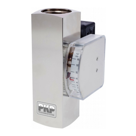
PKP DV08 User manual

Instruction Manual
DV08
Screw-spindle volumetric flow meter
for highly viscous liquids
PKP Prozessmesstechnik GmbH
Borsigstraße 24
D-65205 Wiesbaden- ordenstadt
Tel.: ++49-(0)6122-7055-0
Fax: ++49-(0)6122-7055-50
Email: info@pkp.de

Ta le of Contents
Safety Information..................................................................................................................2
Functional description............................................................................................................3
Installation and commissioning..............................................................................................3
Output signals........................................................................................................................4
Pressure loss.........................................................................................................................8
Accuracy...............................................................................................................................10
Safety Information
General Instructions
To ensure safe operation, the device should only be operated according to the specifica -
tions in the instruction manual. The requisite Health & Safety regulations for a given
application must also be observed. This statement also applies to the use of accessories.
Every person who is commissioned with the initiation or operation of this device must have
read and understood the operating instructions and in particular the safety instructions!
The liability of the manufacturer expires in the event of damage due to improper use, non-
observance of this operating manual, use of insufficiently qualified personnel and unau-
thorized modification of the device.
Proper Usage
The flow meters of the DV08 series are used to measure and display the flow rates of vis -
cous, self-lubricating liquids. Any other use is considered improper.
In particular, applications in which shock loads occur (for example, pulsed operation)
should be discussed and checked in advance with our technical staff.
The devices of the DV08 series must not be used as the sole agents to preventing dan-
gerous conditions on machines and systems. Machines and systems must be designed in
such a way that faulty conditions lead to a dangerous situation for the operating person -
nel.
Dangerous su stances
For dangerous media such as e.g. Oxygen, Acetylene, flammable or toxic substances as
well as refrigeration systems, compressors, etc. must comply with the relevant regulations
beyond the general rules.
Qualified Personnel
DV08 Instruction manual 04/2019 page 2

Devices of the DV08 series may only be installed by suitable trained specialist personnel
who are able to install the devices properly. Qualified personnel are those persons who
are familiar with the assembly, installation and commissioning of devices of this type and
who are approbriately qualified.
Inward Monitoring
Please check directly after delivery the device for any transport damages and deficiencies.
Additional with reference to the accompanying delivery note the number of parts must be
checked.
Claims for replacement or goods which relate to transport damage can only be considered
valid if the delivery company is notified without delay.
Functional description
The flow meter DV08 is used for quantitative flow measurement of viscous liquids. The
liquid flow causes two screw spindles to rotate in opposite directions. A magnetic pre-ten -
sioned hall sensor located outside the flow chamber detects the screw flanks and gener-
ates a flow-proportional frequency signal. Two pulses corresponds to one revolution of the
screws and thus to a certain measuring volume. There are no magnets in the flow cham-
ber.
Installation and commissioning
The Dv08 flow meters are in-line devices with either an aluminium adapter with female
thread or a SAE flange with female thread on the process side. o special inlet or outlet
sections are required.
•Check that the maximum pressures and temperatures specified for the devices are
not exceeded by the pressures and temperatures in the process and that the
materials used in the device for the parts in contact with the product are not
attacked by the medium.
•Make sure that the pipes have been cleaned and flushed prior to installation and
that there are no foreign objects in the pipe.
•Pressure surges caused by sudden changes in flow may damage the unit. Care
must therefore be taken to open valves slowly to avoid pressure surges.
DV08 Instruction manual 04/2019 page 3

Output signals
The Dv08 flow meters can be equipped with various electronics which provide different
output signals.
Pulse output
Depending on the size, the DV08 delivers a certain number of pulses per litre:
Connection size Meas. range l/min Volume/Pulse Pulses/Litre
G 1 1,4...140 13,1 76,3
G 1 ¼ 3,5...350 29,0 34,5
G 1 ½ 5,5...550 48,6 20,6
G 1 ½ 8,0...800 72,0 13,9
G 2 10,0...1000 103,6 9,7
G 2 15,0...1500 133,0 7,5
G 2 ½ 25,0...2500 238,8 4,2
The push/pull output … IW (with cube plug) or ...IR (with round plug) is compatible with all
standard P P or P inputs.
Electrical connection: push-pull output
with 4-pin round plug connector
with cube plug according to DI 43650-A / ISO 4400
DV08 Instruction manual 04/2019 page 4

Frequency converter
The frequency converter supplies an output frequency proportional to the flow rate. The
final value can be set at the factory according to customer requirements and can be up to
2 kHz.. If no end frequency is specified by the user, the standard frequency range is 0...2
kHz = 0...measuring range end.
However, the permanently programmed end value can be assigned to any flow value on
site.
Programming:
1. Set the maximum flow rate in the system
2. Apply a pulse of a least 0,5 s duration to pin 2 or white strand (with cable outlet)
e.g. by jumper to supply voltage or pulse from PLC). The Sensor is now adjusted to
0...max. Output frequency = 0...when programming the set flow rate.
3. After programming, pin 2 (or the white strand) must either remain unconnected or
be connected to 0 V.
Electrical connection:
DV08 Instruction manual 04/2019 page 5

Switching output
With the raid of the integrated sensor, the electronics receives a frequency signal propor -
tional to the flow rate and evaluates it. If the value falls below the set limit value, an alarm
signal is output and the yellow LED in the plug connection goes out.
Programming
1. Set the setpoint frequency (= setpoint flow rate) in the system.
2. Apply a pulse of a least 0,5 s duration to pin 2 or white strand (with cable outlet)
e.g. by jumper to supply voltage or pulse from PLC). Immediately after program-
ming, the sensor switches to alarm status. The alarm is cancelled as soon as the
flow rate has been increased to such an extent that the switching value plus 12 Hz
(=hysteresis) is reached.
3. After programming, pin 2 (or the white strand) must either remain unconnected or
be connected to 0 V.
Electrical connection:
DV08 Instruction manual 04/2019 page 6

Analogue output
With the aid of the integrated sensor, the electronics receives a flow-proportional fre -
quency signal and converts it into an analogue output signal. A current signal 4...20 mA is
generated in the M7I version and voltage signal 0...10 V in the M7U version.
By default, the analogue output is set to:
4...20 mA (or 0...10 V) = 0...upper range value set.
This setting can be changed on site as follows:
Programming:
1. Set the setpoint frequency (= setpoint flow rate) in the system.
2. Apply a pulse of a least 0,5 s duration to pin 2 or white strand (with cable outlet)
e.g. by jumper to supply voltage or pulse from PLC). The electronics is now pro-
grammed so that the set flow corresponds to the maximum value of the analogue
output (20 mA bzw. 10 V).
3. After programming, pin 2 (or the white strand) must either remain unconnected or
be connected to 0 V.
Electrical connection:
High temperature connection
The high temperature connection for the HT version has a 30 cm remote electronics, for
media temperatures up to 150 °C.
Electrical connection:
DV08 Instruction manual 04/2019 page 7

Pressure loss
The pressure loss results from the flow rate and the viscosity of the liquid to be measured.
Higher viscosities result in higher pressure loss. Higher viscosities than listed here are
easily possible, but require a higher pumping capacity.
DV08 Instruction manual 04/2019 page 8

DV08 Instruction manual 04/2019 page 9

Accuracy
The maximum measuring error is +/- 1 % of the measured value. If the flow ranges are
limited to 20 % - 80 % FS, the measurement erors are reduced. If the medium has a vis -
cosity > 170 m2/s, the accuracy is also improved.
Test viscosities were 2 / 22 / 170 mm²/s
DV08 Instruction manual 04/2019 page 10

Flow Measurement and Monitoring
DV08
Screw-Spindle Volumetric
Flow Meter for Highly
Viscous Liquids
•hea y duty design, aluminium housing,
max. 160 or 350 bar
•for 1“ to 2½“ pipe
•unaffected by the iscosity, density
or conducti ity of the medium
•output signals: pulse signal, programmable
frequency output, 4...20 mA,
0...10 V, limit switch
•max. medium temperature 80 °C,
optional up to 150 °C
Description:
The DV08 flow meter is fitted with twin helical screws, which
rotate in opposite directions due to the flow of product being
monitored. The rotational speed is proportional to the flow
rate. The rotary motion of the screws is detected by a sensor
which emits two pulses per revolution. Each pulse signal rep-
resents a pre-defined volume of product. The flowmeter
doesn t have to be taken out of the pipe system for changing
the pick-up system because the pick-up is hermetically
sealed from the medium. The viscosity of the product has vir-
tually no effect on the DV08 due to the volumetrical measure-
ment technique used.
Typical applications:
The DV08 can be used for flow measurement, monitoring and
totalizing of liquid, viscous and self-lubricating products up to
40,000 mPas. The device is suitable for use in hydraulic sys-
tems, and for lubricant monitoring, metering soaps, pastes
and emulsions – to name but a few of its application areas.
PKP Prozessmesstechnik GmbH
Borsigstr. 24 • D-65205 Wiesbaden
S +49 (0) 6122-7055-0 • +49 (0) 6122 7055-50
[email protected] • www.pkp.de
PKP Process Instruments Inc.
10 Brent Drive • Hudson, MA 01749
S +1-978-212-0006 • +1-978-568-0060
[email protected] • www.pkp-usa.com
181010

Models/Materials:
DV08. …: housing: aluminium 6082
screw-type spindles: steel 1.4460
bearing: steel 1.4460
gaskets: FKM
process connection: aluminium (160 bar)
or steel (350 bar)
Measuring ranges:
Connec-
tion size
Measuring
range*
[l/min]
Output
frequency
at Qmax
[Hz]
Process connection
Female thread
"G"
aluminium
Pmax. 160 bar
S E flange
with female
thread,
steel,
Pmax. 350
bar
G 1 1,4...140 254,5 GA25 SAE25
G 1 1/4 3,5...350 287,4 GA32 SAE32
G 1 1/2 5,5...550 274,5 GA40A SAE40A
G 1 1/2 8...800 277,8 GA40 SAE40
G 2 10...1000 257,3 GA50A SAE40A
G 2 15...1500 275,7 GA50 SAE50
G 2 1/2 25...2500 265,2 GA65 SAE65
* the maximum measuring ranges are indicated in each case. For higher
viscosities, the full scale value of the measuring range can be adjusted
due to the of a larger differential pressure will be lower.
Dimensions:
Female thread SAE flange with female thread
Order Code:
Order number: DV08.
Screw-spindle volumetric
flow meter for highly viscous liquids
. V. G 25. IW. 0
Material:
A = aluminium / steel
S = special order
Gasket:
V = FKM (standard)
S = special order
Measuring range / Process connection:
GA25 … SAE65 acc. to table „measuring ranges”
99 = special connection / special measuring range
Output signal (configurable on site):
IW = pulse output (Push/Pull), cube plug
IR = pulse output (Push/Pull), round plug M12x1
M5 = frequency converter (programmable, 0...2 kHz)
M6 = switch output (limit, programmable)
M7I = with F/I-converter (output 4…20 mA)
M7U = with F/ U-converter (output 0…10 V)
HT = high temperature version
round plug M12x1
Options:
0 = without
1 = high temperature version up to 150 °C, 30 cm
detached electronics (with output HT only)
2 = encapsulated ball bearings in case of pressure
fluctuations / -impacts
9 = please specify in plain text
Accessory:
M12 plug connector with PVC cable:
SM12.4, 4-pole
2, 5 or 10 m length,
straight or angled
Technical Data:
Max. pressure:
with thread-
connection (AL): 160 bar
with SAE flange: 350 bar
Medium-temperature: −25...+80 °C
(optional bis 150 °C)
ccuracy: ± 1% of measured value
Repeatability: ± 0,25%
Medium: oil or other, non aggressive,
self-lubricating products
Power supply: 10–30 VDC
Protection class: IP65
Size table [mm]:
G x1 x2 L1 L2 ØD B C M H E F
G 1 20 20 220 324 88 49 57,1 27,8 12 52 80 69
G 1 1/4 22 22 285 381 103 55 66,7 31,6 14 48 94 77
G 1 1/2 24 24 340 456 138 66,5 79,4 36,5 16 58 106 89
G 2 33 35 405 553 168 77,3 96,8 44,4 20 74 135 116
G 2 1/2 35 42 475 633 203 86 123,8 58,7 24 79 166 150
PKP Prozessmesstechnik GmbH
Borsigstr. 24 • D-65205 Wiesbaden
S +49 (0) 6122-7055-0 • +49 (0) 6122 7055-50
[email protected] • www.pkp.de
PKP Process Instruments Inc.
10 Brent Drive • Hudson, MA 01749
S +1-978-212-0006 • +1-978-568-0060
[email protected] • www.pkp-usa.com
Flow

PKP Prozessmesstechnik GmbH
Borsigstr. 24 • D-65205 Wiesbaden
S +49 (0) 6122-7055-0 • +49 (0) 6122 7055-50
[email protected] • www.pkp.de
PKP Process Instruments Inc.
10 Brent Drive • Hudson, MA 01749
S +1-978-212-0006 • +1-978-568-0060
[email protected] • www.pkp-usa.com
Table of contents
Other PKP Measuring Instrument manuals