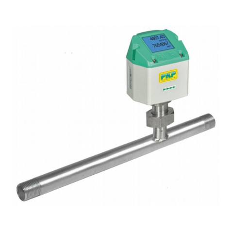
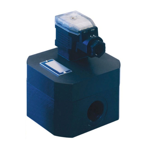
PKP DP07 User manual

Instruction Manual
DP07
Electronic paddle-bellows flowmeter, counter and switch
with analogue output
PKP Prozessmesstechnik GmbH
Borsigstraße 24
D-65205 Wiesbaden- ordenstadt
Tel.: ++49-(0)6122-7055-0
Fax: ++49-(0)6122-7055-50
Email: [email protected] www pkp.de

Table of Contents
Safety Information..................................................................................................................2
Position of Mounting...............................................................................................................4
Mounting at the Tube.............................................................................................................5
Electrical Connection.............................................................................................................6
Settings..................................................................................................................................7
Maintenance.........................................................................................................................11
Technical data......................................................................................................................11
afety Information
General Instructions
To ensure safe operation, the device should only be operated according to the specifica-
tions in the instruction manual. The requisite Health & Safety regulations for a given
application must also be observed. This statement also applies to the use of accessories.
Every person who is commissioned with the initiation or operation of this device must have
read and understood the operating instructions and in particular the safety instructions!
The work safety instructions in this manual as well as the safety, accident prevention and
environmental protection regulations generally valid for the work area must be observed.
The liability of the manufacturer expires in the event of damage due to improper use, non-
observance of this operating manual, use of insufficiently qualified personnel and unau-
thorized modification of the device.
Proper Usage
The flow meters DP07 are designed to monitor continuous flow rates of liquids which do
not attack the device materials. All other usage is regarded as being improper and outside
the scope of the device.
In particular, applications in which shock loads occur (for example, pulsed operation)
should be discussed and checked in advance with our technical staff.
The series DP07 flow meter devices should not be deployed as the sole agents to prevent
dangerous conditions occurring in plant or machinery. Machinery and plant need to be
designed in such a manner that faulty conditions and malfunctions do not arise that could
pose a safety risk for operators.
Dangerous substances
For dangerous media such as e.g. Oxygen, Acetylene, flammable or toxic substances as
well as refrigeration systems, compressors, etc. must comply with the relevant regulations
beyond the general rules.
DP07 Instruction manual 04/2023 page 2

Qualified Personnel
The DP07 devices may only be installed by trained, qualified personnel who are able to
mount the devices correctly. Qualified personnel are persons, who are familiar with assem-
bling, installation, placing in service and operating these devices and who are suitably
trained and qualified.
Inward Monitoring
Please check directly after delivery the device for any transport damages and deficiencies.
Additional with reference to the accompanying delivery note the number of parts must be
checked.
Claims for replacement or goods which relate to transport damage can only be considered
valid if the delivery company is notified without delay.
DP07 Instruction manual 04/2023 page 3

Position of Mounting
It is advantageous to install the unit in a straight piece of pipe and to choose a place of
mounting which has the biggest possible distance from elbows, valves etc.
It is especially important to have the biggest possible distance from magnet valves and ball
valves.
Please make sure that they are opened as slow as possible, and that the valve is mounted
after DP07 unit. These measures prevent the measuring system from flow shocks and tur-
bulences which can cause damages and inaccuracy.
We recommend a straight length of 10 x d at input side and 5 x d at the output side (d =
diameter of pipe).
The apparatus provides a stable signal when installed at closer distances, but depending
on flow conditions it may be less accurate.
Mounting position on electronic view:
Please take in consideration that the mounting has to be done EMI conform in order to
avoid interruptions of operations.
Especially the following points have to be attended:
•The provided ferrites have to be mounted as described.
•Signal and supply cable of the DP07 may not directly taken close to 230 V or 380 V
wirings.
•The device should not be installed close to inductance, switching loads, engines or
similar sources of inductive fields.
Direction of Flow:
It is essential that the unit is mounted so that flow is as indicated by the arrow on the body.
The unit will not operate unless installed correctly in this way and the possibility of damage
to the unit cannot be excluded.
Mounting Orientation:
If the display has to be changed to a new position, it is possible to turn it relative to the
housing. To do this, remove the front and back of the housing and remove the screw
retaining the electronic board to the housing.
Rotate the electronic board to the new desired position taking care not to damage the
cable link, refit and secure the retaining screws. In a similar way, the window on the front
of the access cover can also be turned.
DP07 Instruction manual 04/2023 page 4

Mounting at the Tube
Items with THREAD CONNECTION:
We recommend sealing all threads with PTFE sealing tape. Ensure no excess of tape is
left protruding into the pipe.
When screwing the unit into a pipe, take care to ensure that the housing is not damaged or
impacted during the process.
Items with FLANGE CONNECTION:
An approved flange seal or gasket must be used. either this nor the required fixing bolts
are included in the delivery. Ensure the transmitter is not damaged when tightening the
flange bolts.
Items with welded socket:
The welding socket is included in the delivery. Remove by loosening union nut (A). The
dimensions shown in the drawing (right) must be adhered to strictly to.
Drill a ridge less hole in the pipe. Weld the socket to the pipe. Mount the flow transmitter to
the socket ensuring that the pendulum is not damaged during this procedure. Align the
transmitter into the final desired position before tightening the union nut (A). Please do not
forget to keep the flow direction in consideration before weld on the socket. (groove)
Torsional moment of the union nut:
If the device shall be divided from the t-piece or the welding socket, the union nut has to
be disconnected and the device carefully taken out of the housing.
If both pieces are assembled, please take care that the nut is tightened with a torsional
moment of 40 m.
DP07 Instruction manual 04/2023 page 5

Electrical Connection
Remove the rear access cover to gain access the connector blocks.
(see drawing)
Block KL 2 is for connecting the relays.
Block KL 1 is for connecting power supply and output signals.
The switching position is shown in the idle state (flow is less than the set switching points).
The cables must first be pulled through the corresponding gland of the cover.
Power upply
The supply-voltage is 24 VDC±10%. Connection is to block KL 1 like described at drawing.
In order to prevent the electronic from impermissible potential between pipe and device,
the power supply device must be connected with earth. The connection is prevented from
mixing the poles.
At the connection cable a ferrite must be fixed with one coil. The ferrite is included in deliv-
ery.
DP07 Instruction manual 04/2023 page 6

Analogue output (4-20 mA)
Connection is to block KL 1 according to the drawing. At the connection cable a ferrite
must be fixed. The ferrite is included in delivery.
Voltage output (0-10 V)
Connection is to block KL 1 according to the drawing. (See reference point 4.3) At the con-
nection cable a ferrite must be fixed. The ferrite is included in delivery.
Frequency output
Connection is to block KL 1 according to the drawing. (See reference point 4.3) At the con-
nection cable a ferrite must be fixed. The ferrite is included in delivery.
Connecting the relais
Relays can be connected via block KL 2 as shown on the drawing. At the connection cable
a ferrite must be fixed. The ferrite is included in delivery.
Interface
The DP07 is available to special order with RS232C interface. The special connection
cable is just connected with the device. (See reference “Programming the interface”)
ettings
The device is equipped by 3 buttons on the front side of the enclosure. The button P has
the function to choose a point of the menu and to take over the wished values. With the
buttons and you can set a value. Button increases value. Button decreases the
value. Pressing this button one time the value changes for one digit.
If you keep the buttons on hold the value is changing continuously. After some time velo-
city is increasing. At some points of the menu the DP07 informs you which buttons have to
be pressed as next step.
For example PI [+/-], whereby + corresponds to button and – to button .
The device returns back automatically after some time to the modus set under MODE
(point Analogue output) if no button is pressed. The actual point of the menu is always
shown in the first line, the chosen value in the second line.
Function BATT CHECK
The BATT CHECK function is used for giving the user information that the device was not
in use for a certain time due to power interruption and therefore the amounts of flow could
not get accumulated during that time by the totalizer. Therefore the device should always
be on (O ) when using the totalizer function.
If the totalizer is not used, we would advise to switch-off this function (OFF), as otherwise
the device will only work after restart in case of power loss.
The menu can be operated with P and the functions with or . To take over the reques -
ted adjustment please push P again.
DP07 Instruction manual 04/2023 page 7

Adjusting the relays
Press button P until RELAIS 1 appears. Line 2 shows the actual switch point.
Pressing or the wished switch point can be adjusted. For setting the switch point P
has to be actuated * is appearing. After some time the sigh is disappearing. Adjusting the
switch point of RELAIS 1 is now completed. Actuate P button once more causes changing
to RELAIS 2. Adjustment is like described under RELAIS 1.
When the adjusted value is reached, a lamp glows for control. The green one (A) is
assigned to RELAIS 1 the red one to RELAIS 2 (B)
Adjusting of output occupancy
The DP07 comes with current, voltage and frequency output. The different output types
only can be used alternatively. It is only one pair of connector existing for all functions.
Connection is to block KL1 (see drawing of the board). At menu OUTPUT analogue,
voltage or frequency output can be activated. With the buttons and you can set the
wished function. Button P takes over the adjustment.
At the option frequency output the max. frequency can be adjusted between 125-32000
Hz. Therefore button P must be pressed after entering the frequency function. Then the
max. frequency can be adjusted with the buttons and . ow the adjusted max. fre -
quency corresponds to the upper range value.
Adjusting of standard indication mode
It is possible to choose between 2 different indication modes.
At the point in the menu MODE you can select the modes. In the second line the valid
mode is shown. FLOW means indication of momentous flow. TOTAL means that the value
of totalizer is shown. You can choose the required indication by using button or . But -
ton P takes over the adjustment.
Only the selected standard indication is permanent visible. All other points of the menu
turn back to the standard indication after some time automatically.
Adjusting of integration time
The DP07 Flow transmitter makes 18870 measurements pro minute. If the result of each
measurement would be shown on the display, the indication would change it’s worth con -
tinuously and it would be very difficult to read off the indication. Therefore it is possible to
program an integration time between 0 and 3,4 s. Then the average value of the values
measured within the programmed time is shown. A long integration time causes a slowly
changing indication which is easy to read. We recommend to maintain the standard adjust-
ment of 1 s. For changing the integration time you can choose the wished time with help of
the buttons and in menu I T.[s]. Button P takes over the adjustment.
DP07 Instruction manual 04/2023 page 8

The totalizer
The device is equipped by a totalizer, which adds the flow quantity. (Menu point TOT: X.)
X corresponds to the respective quantity. The unity results from flow unity. (for example
l/min corresponds to l). Actuating button push down the memory to zero.
PRESS <+> to reset appears (+ = ). ow actuate as long as the appearing counter is
executed (20 s).
In case of power failure or too low current the actual amount will be ensured. If necessary
voltage is back again the device notifies POWER LOW / PRESS P & respectively
PRESS P & . Pressing P and (at same time) DP07 changes back to standard modus.
After that the device starts counting from the amount has been present at the time of
power failure. This guarantees that the operator is aware of that power supply was inter-
rupted and so the amount indicated perhaps not corresponds to the real quantity.
Attention:
The power failure supervising function only works if at menu point BATT CHECK the func-
tion is activated (O )
The device has a 8 digit display so a big capacity is available. evertheless depending on
unity, flow quantity and time of flow the capacity may be quite different. If the max. indica-
tion value is reached, DP07 starts with zero again. At the totalizer menu you see the actual
value in the moment of switch over to the totalizer function. That means always when the
totalizer menu is actuated the indication is updated.
The actual value only is indicated if the totalizer is defined as standard indication.
Restriction of access by code number
In order to restrict of access of not authorizes persons to the programmed dates it is pos -
sible to activate a code number. In the point of menu PI [+/-] it is possible to adjust any
code number between 1 and 999 by help of the buttons and . By pressing P and at
the same time the programmed code number is activated. E ABLE is appearing. If an
adjustment in any menu now should be changed the operator is asked for the code num-
ber. The number can be entered liked described above. After that PI OK! Is appearing.
ow the adjustment can be changed. If PI OT OK! is appearing input was wrong. You
now can repeat entering the code number.
Attention:
Should the number be forgotten the adjustments can not be changed any more.
At point of menu PI [+/-] restriction of access can be switched off. Therefore code num -
ber has to be entered as described above. PI OK! and thereafter DISABLE is appearing.
Programming the interface
Under point of menu ADR: the address of each device can be programmed (selection by
, input by P). For more details please see our data sheet for devices with interface. It is
only added to devices which are equipped with this option.
DP07 Instruction manual 04/2023 page 9

Mounting the ferrite
The flow transmitter DP07 is EMI certified and comes up to the corresponding norm. The
EMI directive will only be achieved, if the provided ferrites are mounted as mentioned
under “Power Supply”, “Analogue output”, “Voltage output”, “Frequency output”, “Connect -
ing the relays”. If not, serious malfunctions can be appeared depending on the mounting
position.
IMPORTA T: Always mount the ferrite
Protection on data loss
If your device is operated on incorrect EMI conditions, it could come to data loss respect-
ively damages of coded data in extreme cases.
As the item need these data for a correct function there hereby is an anticipate protection.
In this case the item is showing K DATA MISSI G.
So that this information is available for the occupant, even in case of a use of the ana -
logue-voltage or frequency output, impermissible values will normally be transferred.
These are 1 mA, 20 V, respectively 0 Hz.
In order to re-establish the function of the item in such a case, the necessary software is
saved additionally for safety reasons. The software can be load again with the menu item
FACTORY RESET.
Therefore push the button or in the menu FACTORY RESET. You will be asked to
start the action (Y) button or to break up ( ) button .
ATTE TIO !
When starting the application, all adjusted data as switch points, totalizer value etc. will be
lost. (Reset to the original factory setting)
Please consider this and keep the data before starting the procedure in mind.
After the reestablishment has been started, you will get informed about the status of the
procedure. When the flow indication on the display appears, the operation is over. The
device is working as usual again. Please consider that e.g. the switch points have to be
new installed again.
We would like to point out, that the data loss occurs only if the item is used under forbid -
den conditions.
Therefore it is really necessary to open corresponding arrangements in order to avoid a
new data loss.
This could be:
•mounting the provided ferrites
•installation of the device at another position
•changing the cabling within the installation (no measure or feed lines of the trans-
mitter near high voltage feed cable).
•Reducing of radiation or magnetic field
•installation of suitable electrostatic shields
DP07 Instruction manual 04/2023 page 10

Maintenance
The DP07 is essentially maintenance-free. However, depending on the degree of pollution
in the medium, it is recommended that the sensor system be inspected and cleaned as
necessary from time to time.
Under no circumstances attempt to remove the pendulum from the unit as this will destroy
the calibration. Clean the pendulum system before re-installing into the pipe.
IMPORTA T!
If the DP07 must be separated from the tee loosen nut (A) and cant the unit a little
opposed to direction of flow. Then lift the DP07 with pendulum rectangular out of the tee.
Please perform all disassembly/reassembly operations with great care. Avoid damage!
Especially to the pendulum system.
Technical data
- Power supply : 24 VDC ± 10 %
- Current drain: 200 mA max.
- Contacts: 2 x 230 V, 1 A max
- Analogue output: 4-20 mA
- Voltage output: 0-10 V
- Display: LCD DOT-Matrix-Module 2 x 8 digits (illuminated)
- Medium temperature: -20 ... +100 °C (special versions dissonant)
- Max. pressure: 25 bar (special versions dissonant)
DP07 Instruction manual 04/2023 page 11

Flow Measurement and Monitoring
DP07
Electronic Paddle-Bellows
Flowmeter, Counter and Switch
with Analogue Out ut
•for liquids
•2-line LCD-dis lay for flow rate
or total quantity
•linearised analogue out ut signal
4...20 mA or 0...10 V
•2 inde endent limit switches
•o tional RS-232-interface
•intensitive to dirty / contaminated
media
•easy installation, for i ing
u to DN 600
•measuring ranges: 1,5...600 l/min to 420...4500 m³/h
•Pmax: 25 bar, Tmax: 100 °C
Description:
The DP07 flowmeter work according to the paddle-bellows
principle. By the flow of the liquid the paddle arm is mo ed in
the direction of the flow against the force of a spring. This
motion is transferred to a magnet and its position is detected
by a Hall sensor. A microprocessor based electronic unit cal-
culates according to a calibration cur e the actual flow of the
medium.
A two chamber system assures that e en in the case of a
de ice fault no medium can ingress the electronic housing.
Typical applications:
The DP07 flow transmitters are used to super ise the flow of
low iscosity media up to large flows.
Especially in the case of pipes bigger than DN 50 there is an
unchallenged price performance ratio due the use of a weld
on nozzle.
PKP Prozessmesstechnik GmbH
Borsigstr. 24 • D-65205 Wiesbaden
S +49 (0) 6122-7055-0 • T +49 (0) 6122 7055-50
[email protected] • www.pkp.de
20181114

Models:
The flow monitors DP07 are a ailable in 3 ersions each
and materials combinations a ailable:
DP07.R… with T-fitting and pipe thread connection
...A: brass: with female thread from R 3/8 to R 1 1/2
with male thread from R 1 to R 2
...B: st. steel: with female thread from R 3/8 to R 3/4
with male thread from R 1 to R 2
DP07.F… with T-fitting and DIN-flange
on DN 10 bis DN 50
aterial- housing made of brass
combination A:T-piece made of brass
pi oting system made of st. steel 1.4310
flange of gal anized carbon steel
aterial- housing made of st. steel 1.4301
combination B: T-fitting made of st. steel 1.4571
pi oting system made st. steel 1.4310
flange made of st. steel 1.4571
aterial- T-fitting made of PVC
combination C: pi oting system made of st. steel
1.4310
flange made of PVC
DP07.A… with weld-on flange
for nominal pipe size DN 65 to DN 600
aterial- housing made of brass
combination A: pi oting system made of st. steel 1.4310
weld-on flange made of st. steel 1.4301
aterial- housing made of st. steel 1.4301
combination B: pi oting system made of st. steel
1.4310
bellows made of st. steel 1.4571
weld-on flange made of st. steel 1.4301
Dimensions:
Order Code:
Order number: DP07.
Electronic paddle bellows flowmeter, counter
and switch, with analogue output
R025. B. 1. 20-100
Process connection (xx=nominal pipe size):
R0xx = with female or male thread*
F0xx = with flange (DN 10 to DN 50 only)
Axxx = with weld-on nozzle (from DN 65 to DN 600)
aterial combination:
A = brass / st. steel (gal anized steel)
B = complete stainless steel
C = PVC / stainless steel (not for DP07.A..)
Output signals:
0 = uni ersal output for current, oltage and frequency
(adjustable on site)
2 relays, SPDT
Switching range:
xxxx-xxxx = min. - max. flow (see table „Measuring ranges“)
*female thread DP07...A: R 3/8 bis R 1 1/2; DP07...B: R 3/8 bis R 3/4
male thread DP07...A: R 2; DP07...B: R 1 bis R 2
Additional s ecifications:
• medium density and viscosity (if different from water)
• o erating ressure and tem erature
• mounting osition and flow direction
Measuring Ranges:
Process
connection
DP07.R...
DP07.F...
Flow
[l/min]
Flow
rate
Process
connection
DP07.A…
Flow
[m³/h]
Flow
rate
min. max. min. max.
3/8"/DN 10 1,5 25 1:10 DN 65 4,8 60 1:10
1/2"/DN 15 1,5 45 1:10 DN 80 7,2 90 1:10
3/4"/DN 20 5 100 1:10 DN 100 12 144 1:10
1"/DN 25 6 150 1:10 DN 125 18 255 1:10
1 1/4"/DN 32 10 250 1:10 DN 150 24 330 1:10
1 1/2"/DN 40 20 400 1:10 DN 200 42 600 1:10
2"/DN 50 50 600 1:10 DN 250 72 900 1:10
Switching ranges apply to water, 20 °C.
All switching ranges can be implemented
within the specified limits, pro ided that the
ratio of max. to min. switching point is not
exceeded.
e.g. in the case of 3/4“:
5...50, 8...80 or 10...100 possible.
DN 300 102 1.200 1:10
DN 350 150 1.800 1:10
DN 400 180 2.400 1:10
DN 500 300 3.600 1:10
DN 600 420 4.500 1:10
Nominal size Installation length Z [mm] Installation
height H
[mm]
DP07.R… DP07.F…
3/8"/DN 10 50 155 157
1/2"/DN 15 50 155 157
3/4"/DN 20 50 155 157
1"/DN 25 135 155 DP07.x.A: 162
DP07.x.B: 178
1 1/4"/DN 32 170 190 DP07.x.A: 167
DP07.x.B: 178
1 1/2"/DN 40 170 190 DP07.x.A: 171
DP07.x.B: 178
2"/DN 50 170 190 DP07.x.A: 179
DP07.x.B: 188
Technical Data:
max. pressure: DP07.R and DP07.A: 25 bar
DP07.F: 16 bar
max. med.-temperature: 100 °C
Accuracy: ± 2 % of final alue
Outputs: 4...20 mA, 0...10 V, freq. output.
(programmable max. 32 kHz)
2 x relay SPDT, 230 V, 1 A
Power supply: 24 VDC +/- 10 %
Power input: max. 200 mA
Protection class: IP65
Totalizer: with EPROM – memory
PKP Prozessmesstechnik GmbH
Borsigstr. 24 • D-65205 Wiesbaden
S +49 (0) 6122-7055-0 • T +49 (0) 6122 7055-50
[email protected] • www.pkp.de
Flow
Table of contents
Other PKP Measuring Instrument manuals
Popular Measuring Instrument manuals by other brands

Blanco
Blanco DigiFlow 8300T-22F manual

PCB Piezotronics
PCB Piezotronics IMI SENSORS 645B02 Installation and operating manual

Measurlogic
Measurlogic DTS 310 quick start guide

Hioki
Hioki CM3289 instruction manual

Hach
Hach POLYMETRON 8810 Basic user manual

Spectrum Technologies
Spectrum Technologies Macroscope 45 product manual

Leica
Leica Disto X310 Assembly manual

domat
domat THERMASGARD TM43 Operating Instructions, Mounting & Installation

AccuEnergy
AccuEnergy AXM-WEB Brief overview

Gold Standard
Gold Standard ThunderBolt user manual

Honeywell
Honeywell E-Mon Class 1000 quick start guide

Agilent Technologies
Agilent Technologies PSA Series Installation notes