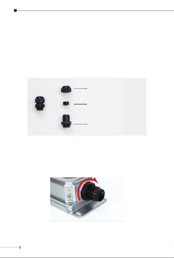
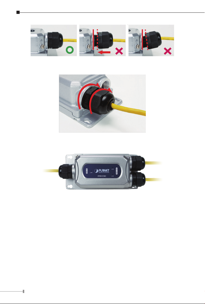
Planet IPOE-E302 User manual

Industrial IP67 1-Port 802.3bt PoE++ to
2-Port 802.3at/bt Gigabit PoE Extender
IPOE-E302
User's Manual

Table of Contents
1. Package Contents................................................................................. 3
2. Hardware Introduction .......................................................................... 4
2.1 Product Outlook............................................................................. 4
2.2 802.3bt PoE++ Input Port .............................................................. 4
2.3 802.3at/bt PoE+ Output Port .......................................................... 5
2.4 LED Indicators............................................................................... 5
3. Installation .......................................................................................... 6
3.1 Installing Cable Gland with RJ45 UTP Cable ..................................... 6
3.2 Connecting Waterproof Cable Kit to the Outdoor PoE Extender .......... 6
3.3 Wall-mount Installation .................................................................. 9
3.4 Grounding the Device................................................................... 10
3.5 Connecting IPOE-E302 to PSE....................................................... 11
3.6 Connecting IPOE-E302 to PD ........................................................ 11
4. Power over Ethernet Budget................................................................ 13
5. ProductSpecications ......................................................................... 16
6. Customer Support .............................................................................. 19

3
1. Package Contents
Thank you for purchasing PLANET Industrial IP67 1-port 10/100/1000T 802.3bt
PoE++ to 2-port 10/100/1000T 802.3at/bt PoE++ Extender, IPOE-E302. In the
following sections, the term “Outdoor PoE Extender” means the IPOE-E302.
Open the box of the Industrial PoE Extender and carefully unpack it. The box
should contain the following items:
IPOE-E302 x 1 M22 Waterproof Cable
Gland x 3 Spanner x 1
QR code sheet x 1 Mounting Kit x 1 Ground Wire x 1
If any of these are missing or damaged, please contact your dealer
immediately; if possible, retain the carton including the original packing
material, and use them again to repack the product in case there is a need to
return it to us for repair.
Remarks: The color of the ground wire is dierent according to the batch, but
itswirespecicationsmeetthestandard.

4
2. Hardware Introduction
This section describes the functionalities of the Outdoor PoE Extender’s
components.
2.1 Product Outlook
Unit: mm
PoE++ In
PoE++ Out
IPOE-E302
LNK/
ACT
LNK/
ACT
LNK/
ACT
Figure 2-1: IPOE-E302 product outlook
2.2 802.3bt PoE++ Input Port
Figure 2-2 shows the PoE++ input port side of the IPOE-E302
Figure 2-2: IPOE-E302 PoE++ Input Port Side

5
2.3 802.3at/bt PoE+ Output Port
Figure 2-3 shows the two PoE+ ouput ports side of the IPOE-E302.
Figure 2-3: IPOE-E302 PoE++ Output ports side
2.4 LED Indicators
LED Color Function
LNK/ACT Green
Lights to indicate the port is linked up at
10/100/1000Mbps.
Blinks to indicate that the IPOE-E302 is actively sending
or receiving data over that port.

6
3. Installation
This section describes how to install the Outdoor PoE Extender and make
connections to it. Please read the following sections and perform the procedure
in the order being presented.
3.1 Installing Cable Gland with RJ45 UTP Cable
The cable gland consists of the following
A. Clamping Nut
B. Sealing Insert
C. Body (with Rubber Washer)
3.2 Connecting Waterproof Cable Kit to the Outdoor PoE
Extender
Step 1: Turn clockwise to tighten the gland body connected to the Outdoor
PoE Extender.

7
Step 2: Plug the RJ45 connector into the connector of the PoE++ In port.
Step 3: Insert the sealing insert into the cable gland body.
Step 4: Attach the clamping nut to the cable gland to complete the cable
assembly.
Caution
Make sure the clamping nut is tightly attached to the cable
gland body and the sealing insert is squeezed tightly.

8
Step 5: Repeat Steps 1 to 4 for two PoE++ Out ports.

9
1. Use only the waterproof cable gland provided in the package
of the IPOE-E302.
2. If the above installation procedure is not properly followed,
the warranty will be invalidated.
11.31mm
40.78mm
5.00mm
30.22mm
29.80mm
20.18
13.72
14.00
30.10
3. If the waterproof cable gland is found missing or damage,
please contact your local reseller where you purchased from.
4. Never use any waterproof cable gland that is not purchased
from PLANET or doesn’t have the same dimensions of the
IPOE-E302; it will damage the device permanently.
3.3 Wall-mount Installation
To install the Outdoor PoE Extender on the wall, please follow the instructions
described below.
Step 1: Find the wall that you want to mount the Outdoor PoE Extender on.
Step 2: Refer to the picture below to screw the four screws on the wall.
140.00mm
129.00mm
60.00mmØ
4.50mm
Ø7.00mm

10
Step 3: Use a screwdriver to screw them into the wall.
3.4 Grounding the Device
Users MUST complete grounding wired with the device; otherwise, a sudden
lightning could cause fatal damage to the device.
Earth Ground
EMD (Lightning) DAMAGE IS NOT COVERED UNDER WARRANTY.

11
3.5 Connecting IPOE-E302 to PSE
The Outdoor PoE Extender has three RJ45 ports of which one is the PoE++
In port connected to the PSE and the other two are PoE+/ PoE++ Out ports
connected to the PDs.
Step 1: Connect a standard Cat5e/6 UTP cable from a remote PSE, such as
PoE switch, to the “PoE++ In” port of the IPOE-E302.
Power
Data
100m
802.3bt PoE Switch (PSE) IPOE-E302
Step 2: The PSE delivers both Ethernet Data and PoE power over UTP cable
to the IPOE-E302 and the “LAN” LED will be lit steadily.
Note
1. If the LED is not lit, please check the remote PSE or the
cable connecting to a PC or a network device to see if the
cable is correct. Or with an 802.3at/bt device such as the
target PD, check whether the power injection is correct.
2. Never connect any non-standard PoE PSE to the IPOE-
E302; it will damage the device permanently.
3.6 Connecting IPOE-E302 to PD
Step 1: Connect the additional Cat5e/6 cable from the PoE++ Out of the
IPOE-E302 to a remote PD.
PoE Wireless AP
PoE Camera
IPOE-E302
Power
Data
100m
Power
Data
100m

12
Step 2: The PoE++ Out port is also the power injector which transmits
DC voltage to the Cat5e/6 cable and transfer data and power
simultaneously between the PSE and PD.
Step 3: Once the IPOE-E302 detects the existence of an IEEE 802.3at/bt
device or Ethernet device, the LAN LED indicator will be lit steadily,
showing it is providing power.
60-95W
30W
PoE Dome IP Camera
802.3bt PoE++
802.3at PoE+
Power
Data 100m
100m
802.3bt PoE++
100m
PoE Dome IP Camera
802.3af PoE
100m
802.3af PoE
100m
50W+25W
PoE Extender
802.3bt PoE++ Injector/Switch
1 In 2 Out
802.3at PoE+
Power
Data 100m
10W+10W
802.3at PoE+ Injector/Switch
PoE Extender
1 In 2 Out
Note
1. According to IEEE 802.3at/bt standard, the IPOE-E302 will
not inject power to the cable if not connected to a standard
IEEE 802.3at/bt device.
2. DO NOT connect any non-standard PSE to PoE++ In port of
the IPOE-E302; it may damage the device permanently.

13
4. Power over Ethernet Budget
The following table lists how many PoE devices can be powered by the IPOE-
E302 over a distance of under 1m:
Power Source PoE Output
Budget* Max. Number of PDs supported
IEEE 802.3bt PoE++
PSE (Type 4) 90 watts max.
IEEE 802.3bt PoE++
PSE (Type 3) 60 watts max.
IEEE 802.3at PoE+
PSE (Type 2) 30 watts max.
Remarks:
1. The PoE output budget means the aggregated power output of the 2 PSE
ports.
2. The aggregated power consumption will be below 60 watts if with PoE+ PSE.
Power over Ethernet Capability
With dierent distance and dierent PoE input source, it will inect the PoE
output capability. Please refer to the table below.
(A) (B) PoE Output Capacity
(C)
(A): Distance
(B): Distance
(C): Watts
IPOE-E302
802.3bt PoE Switch (PSE)

14
When PoE Switch (PSE) Output is DC 52V.
A (Distance) B (Distance) C (Watts)
60M 2M 52.7W
60M 20M 50.1 W
60M 60M 49.6W
60M 100M 44.9W
100M 2M 39W
100M 20M 37.6W
100M 60M 36.5W
100M 100M 34.6W
When PoE Switch (PSE) Output is DC 54V.
A (Distance) B (Distance) C (Watts)
60M 2M 52.9W
60M 20M 50.8W
60M 60M 49.7W
60M 100M 44.9W
100M 2M 47.2W
100M 20M 45.9W
100M 60M 44.1W
100M 100M 42.2W

15
When PoE Switch (PSE) Output is DC 56V.
A (Distance) B (Distance) C (Watts)
60M 2M 54.1W
60M 20M 53.4W
60M 60M 52.1W
60M 100M 47.4W
100M 2M 51.8W
100M 20M 49.7W
100M 60M 48.2W
100M 100M 46.7W
Note
The table list shown here is for your reference only. The actual
performance should be related to your environment.

16
5.ProductSpecications
Model IPOE-E302
HardwareSpecications
Network Connector
PoE in Port
- 1 x 10/100/1000BASE-T Ethernet with 802.3bt PoE++
“Data + DC” in
- Auto MDI/MDI-X, auto-negotiation RJ45 connector
PoE out Port
- 2 x 10/100/1000BASE-T Ethernet with IEEE 802.3at/bt
PoE++ “Data + DC” out
- Auto MDI/MDI-X, auto-negotiation RJ45 connector
Switch Architecture Store-and-Forward switch architecture
MAC Address Table 2K MAC address table with auto learning function
DataBuer 1Mbit
Switch Fabric 6Gbps
Switch Throughput 4.46Mpps @ 64Bytes
Flow Control IEEE 802.3x pause frame for full duplex
Back pressure for half duplex
Jumbo Frame 9Kbytes
ESD Protection Air 8KV DC,
Contact 6KV DC
Surge Protection 6KV
Enclosure IP67-rated and IK10 aluminum case
Installation Wall-mount ear
LED Display LNK/ACT LED x 3
Dimensions
(W x D x H)
150 x 43.8 x 72.94 mm
169.85 x 43.8 x 72.94 mm, with cable gland
Weight 339g
372g (with three waterproof cable glands)
Power Consumption 95.6 watts / 326.2BTU (Full loading with PoE function)

17
Power over Ethernet
PoE Standard
PoE in Port
- IEEE 802.3bt PoE++ Type 4 standard PD
- IEEE 802.3bt PoE++ Type 3 standard PD
- IEEE 802.3at PoE+ end-span/mid-span PD
Per PoE out Port
IEEE 802.3bt PoE++ end-span/mid-span PSE
PoE Power
PoE in Port
52~57V DC, max. 95 watts
Per PoE out Port
50~55V DC, max. 60 watts
Power Pin
Assignment
PoE in Port
1/2 (-), 3/6 (+), 4/5 (+), 7/8 (-) or 1/2 (+), 3/6 (-),
4/5 (+), 7/8 (-)
Per PoE out Port
1/2 (-), 3/6 (+), 4/5 (+), 7/8 (-)
PoE Power Budget
95 watts (max.) @ 802.3bt PoE++ Type 4 input
60 watts (max.) @ 802.3bt PoE++ Type 3 input
30 watts (max.) @ IEEE 802.3at PoE+ input
IEEE 802.3af PoE input not supported
Standards Conformance
Regulatory
Compliance
FCC Part 15 Class A
CE
Stability Testing
IEC 60068-2-32 (Free fall)
IEC 60068-2-27 (Shock)
IEC 60068-2-6 (Vibration)
Standards
Compliance
IEEE 802.3 Ethernet
IEEE 802.3u Fast Ethernet
IEEE 802.3ab Gigabit Ethernet
IEEE 802.3x Flow Control
IEEE 802.3af Power over Ethernet
IEEE 802.3at Power over Ethernet Plus
IEEE 802.3bt Power over Ethernet Plus Plus

18
Environment
Operating Temperature: -40 ~ 75 degrees C
Relative Humidity: 5 ~ 95% (non-condensing)
Storage Temperature: -40 ~ 85 degrees C
Relative Humidity: 5 ~ 95% (non-condensing)

19
6. Customer Support
Thank you for purchasing PLANET products. You can browse our online FAQ
resource and user’s manual on PLANET web site rst to check if it could solve
your issue. If you need more support information, please contact PLANET
support team.
PLANET online FAQs:
https://www.planet.com.tw/en/support/faq
Support team mail address:
Copyright © PLANET Technology Corp. 2022.
Contents are subject to revision without prior notice.
PLANET is a registered trademark of PLANET Technology Corp.
All other trademarks belong to their respective owners.
Table of contents
Other Planet Extender manuals

Planet
Planet WRE-1200 User manual

Planet
Planet PL-510W User manual

Planet
Planet IHD-200PT User manual

Planet
Planet VC-205PT User manual

Planet
Planet LRE-101C User manual

Planet
Planet LRP-101C-KIT User manual

Planet
Planet WTB-1000 User manual

Planet
Planet POE-E301 User manual

Planet
Planet WNAP-C3220 User manual

Planet
Planet IPOE-E202 User manual

Planet
Planet WBT-1000 User manual

Planet
Planet POE-E101 User manual

Planet
Planet IVC-2004PT User manual

Planet
Planet WNAP-1110 Operator's manual

Planet
Planet LRE-104 User manual

Planet
Planet IPOE-E174 User manual

Planet
Planet LRP-101CE User manual

Planet
Planet LRE-101 User manual

Planet
Planet WNAP-1110 User manual

Planet
Planet VC-203PT User manual