manuals.online logo
Brands
  1. Home
  2. •
  3. Brands
  4. •
  5. POLA
  6. •
  7. Temperature Controllers
  8. •
  9. POLA HP58 User manual

POLA HP58 User manual

HP58
SL 4.0
Handbook
0-10V Proportional
TEMPERATURE SETTING
PressSET(keylampflashes):thismessagewillbedisplayed
instead of the ° Set temperature value .
Press + or -to modify, press SET to escape.
Example with t.SEt = 25.0°
STATE INDICATIONS LAMPS
MAIN SETTING (Run Mode)
INSTALLATION
Press TEMP key for at least 2 seconds to display % insert (PErC message will be
displayed instead of the infra-red lamps power % inserction).
Output Relay
HEAT ON Output Relay
COOL ON
BAR-GRAPH % 0-10V INSERT
The lamps near set key indicates relay command status.
COOL output
contact
HEAT output
contact
230V LINE*
HP58
- +
O-10V output
(min 10 Kohm)
SX temperature
probe *
As it company policy to continually improve the products the Manufacturers
reserve the right to make any modifications thereto without prior notice. They
cannot be held liable for any damage due to malfunction.
11.07.14
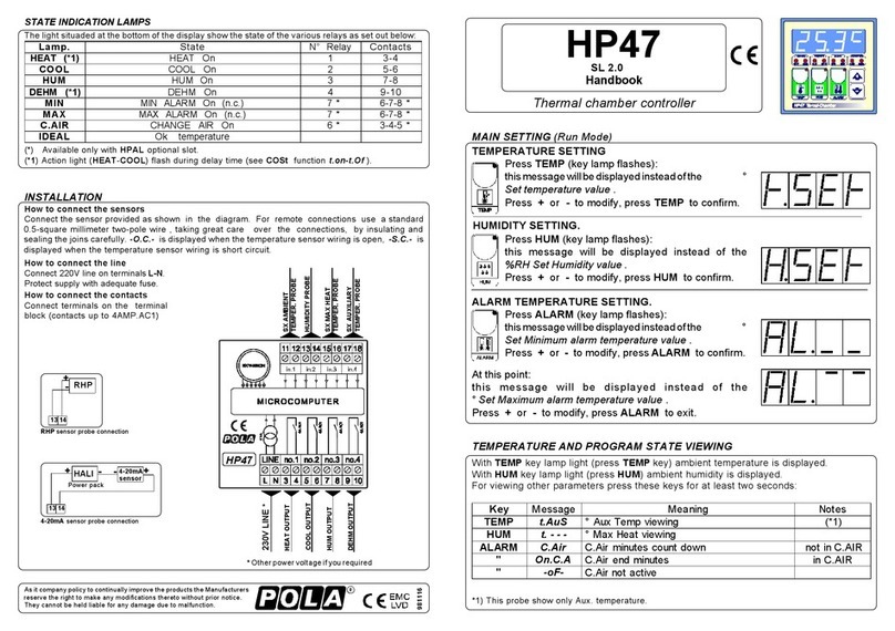
How to connect the sensors
Connect the sensor provided as shown in the diagram.
For remote connections use a standard 0.5-square millimeter two-pole wire,
taking great care over the connections, by insulating and sealing the joins carefully.
-O.C.- is displayed when the temperature sensor wiring is open, -S.C.- is displayed
when the temperature sensor wiring is short circuit.
How to connect the line
Connect line on terminals L-N.
Protect supply with adequate fuse.
How to connect the contacts
Connect terminals on the terminal block (contacts up to 4AMP.AC1).
Press +: will be displayed followed by
°Maximum Temperature Recording.
Press - : will be displayed followed by
°Minimum Temperature Recording.
VIEWING TEMPERATURE RECORDING
Valuesarepermanentlystoredinthememory:fordeletingallvaluesinthememorykeep
pushed + key for more than 3 seconds: CLEA message will appear on display before
clearingoperation.
* Other power voltage if you required.
*4-20mA humidity probe connection (with setting tEnP=3 in COSt).
109R
230V LINE
Example with our
RHR humidity probe R=100ohmresistortobeconnected
in parallel by 9-10 terminals.
*1) For more details see 0-10V Proportional output Operative Diagrams.
*2) For more details see Relay output Operative Diagrams.
*3) =1 : °C Temperature range.
*4) You can correct the readings on the various sensor (+or -).
CYCL = 1"...999"
100% diFF
H 1
OFF
TEMPERATURA
75%
50%
25%
0%
TEMPERATURA
diFF
H 1
ON
OFF
1/2 d.HEA 1/2 d.HEA
CYCL= 0"
*1Relay'soperatingcomputedwith
1% resolution and actioned
minimum0,5 sec.
ON ON
CYCL
CYCL
ON ON
CYCL
OFF
ON
*1 Relay's output in the time.
ON ON
Relay output
Set.t +rELA Set.t +rELA
0-10V Proportional Output
ProP
TEMPERATURE
10V *1
7,5V
5V
2,5V
0V 0V *1
0-10Voutput
computated
with 0,1V
resolution.
10-0V (Negative proportional)
- Prop
TEMPERATURE
10V *1
7,5V
5V
2,5V
0V *1
10V *1
0-10Voutput
computated
with 0,1V
resolution.
0-10V (Positive proportional)
Set.t +rEL.P Set.t +rEL.P
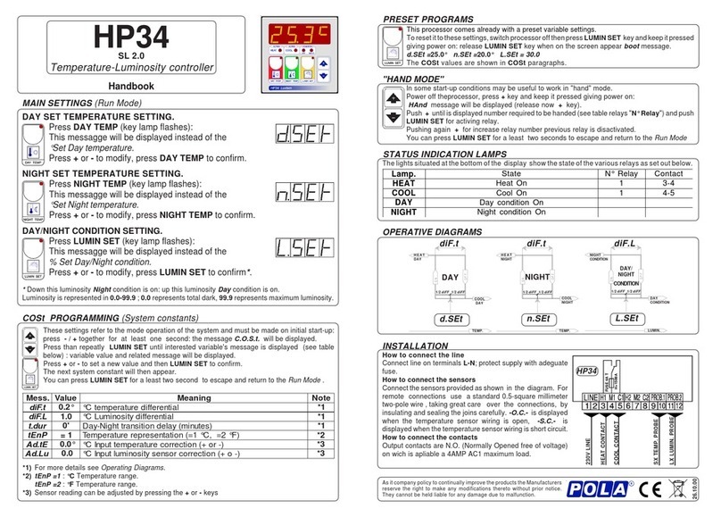
COSt PROGRAMMING (System constants)
Thesesettingsrefer to the operation mode of thesystemand must be made on
initialstartup. Press - / +atthe same time foratleast one second: the message
C.O.S.t. will be displayed.
Press than repeatedly SET until the message regarding the chosen variable is
displayed (see table below) : value of variable and message will be displayed.
Press + or - to set a new value and then press SET to confirm.
The next system constant will then appear.
You can press SET for at least 2 seconds to exit and return to the Run Mode.
=2 : °F Temperature range.
=3 : 4-20mA (0.0%...100.0%). See Installation.
OPERATIVE DIAGRAMS
PRESET PROGRAMS (Bootstrap)
This processor is already programmed with the following (variable) settings.
To return to these settings at any time you may:
Power off the processor, press SET key and keep it pressed giving power on:
boot message will be displayed (release now SET key).
t.SEt =25.0 The COSt values are shown in COSt Programming.
*1 Minimum and maximun output
conditionated by P._ _ _ e P.- - - set.
*1 Minimum and maximun output
conditionated by P._ _ _ e P.- - - set.
In some start-up conditions may be useful to work in "hand" mode:
Power off the processor, press + key and keep it pressed giving power on: HAnd
message will be displayed (release now + key).
Press + untilisdisplayednumberrequiredtobehanded(seerelaystableinState
indication lamps) and push SET for activing relay.
Pressing again + for increase relay number previous relay is disactivated.
You can press SET key for a least two seconds to escape and return to the
Run Mode.
MANUAL MODE
.sseM eulaV gninaeM etoN
P.LEr °0.0 tES.totgnirrefertfihsgnittesV01-0° )1*
PorP °0.2 )tuptuoV01-0(dnablnoitroporP° )1*
___.P %0 muminimtlovtuptuO% )1*
---.P %001 mumixamtlovtuptuO% )1*
ALEr °0.0 tES.totgnirrefertfihsgnittesyaleR° )2*
FFid °2.0 )tuptuoyaler(laitnereffiD° )2*
LCYC "0 )tuptuoyaler(sdnocesniemitelcycnoitalugeromrehT )2*
PnEt 1= noitatneserpererutarepmeT )Am02-4=3,F°=2,C°=1( )3*
Et.dA °0.0 )-ro+(noitcerrocrosneserutarepmettupnI° )4*

Other POLA Temperature Controllers manuals

POLA HP54 User manual

POLA

POLA HP54 User manual

POLA HP55 User manual

POLA

POLA HP55 User manual

POLA HP47 User manual

POLA

POLA HP47 User manual

POLA HP54 User manual

POLA

POLA HP54 User manual

POLA HP34 User manual

POLA

POLA HP34 User manual

Popular Temperature Controllers manuals by other brands

Tahmo Tempi user manual

Tahmo

Tahmo Tempi user manual

Danfoss ECL Comfort 210 installation guide

Danfoss

Danfoss ECL Comfort 210 installation guide

Powtier Controls Tactical 310 instruction manual

Powtier Controls

Powtier Controls Tactical 310 instruction manual

echoflex RTS installation guide

echoflex

echoflex RTS installation guide

TREND Thermistor TBTI installation instructions

TREND

TREND Thermistor TBTI installation instructions

TECSYSTEM NT538 instruction manual

TECSYSTEM

TECSYSTEM NT538 instruction manual

Autonics TS4M instruction manual

Autonics

Autonics TS4M instruction manual

dixell XW562K Installation and operating instructions

dixell

dixell XW562K Installation and operating instructions

MULTISPAN UTC-2200G quick start guide

MULTISPAN

MULTISPAN UTC-2200G quick start guide

Omron E5CC-T manual

Omron

Omron E5CC-T manual

Honeywell T775J Product data

Honeywell

Honeywell T775J Product data

TREND T/PC installation instructions

TREND

TREND T/PC installation instructions

AMX VST-TSF Dimensional drawing

AMX

AMX VST-TSF Dimensional drawing

Hakko Electronics FG-101 Calibration instructions

Hakko Electronics

Hakko Electronics FG-101 Calibration instructions

Resol FRP12 Mounting Connection

Resol

Resol FRP12 Mounting Connection

Uponor Smatrix Base PULSE Installation and operation manual

Uponor

Uponor Smatrix Base PULSE Installation and operation manual

Full Gauge MT-519e manual

Full Gauge

Full Gauge MT-519e manual

eltherm ELTC/H-14 Operation manual

eltherm

eltherm ELTC/H-14 Operation manual

manuals.online logo
manuals.online logoBrands
  • About & Mission
  • Contact us
  • Privacy Policy
  • Terms and Conditions

Copyright 2025 Manuals.Online. All Rights Reserved.