PolyVision Boundri User manual

Boundri™
Installation Guide
Guidelines for installing your new
Boundri privacy screens
Doc # 100128 | Rev D | Page 1 of 10

Doc # 100128 | Rev D | Page 2of 10
Safety Requirements
Tipping Hazard
If handled incorrectly the installation could be tipped over.
Crush Hazard
Panels are heavy. Falling or dropping panels can cause serious injury. Follow all
safety instructions.
Safety Instructions
CAUTION: Contains small parts.
Read all assembly directions on installation guide before beginning installation.
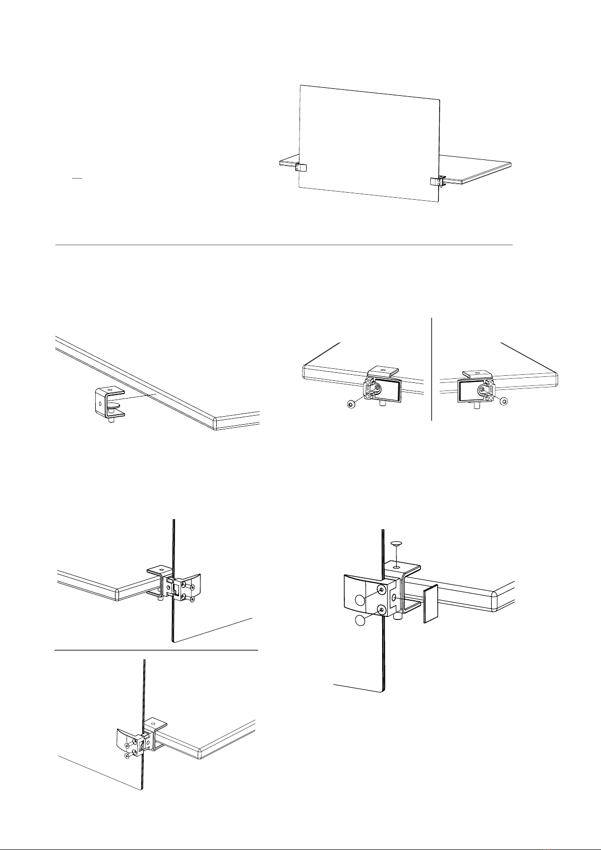
Use all panel clamps for the required panel positions and sizes.
Panel Thickness Inlay Set Up
10 mm - 9 mm 3,00 mm
9 mm - 8 mm 3,00 mm + 0,50 mm
8 mm - 7 mm 3,00 mm + 1,00 mm
7 mm - 6 mm 3,00 mm + 1,00 mm + 0,50 mm
6 mm - 5 mm 3,00 mm + 2,00 mm
5 mm - 4 mm 3,00 mm + 2,00 mm + 0,50 mm
4 mm - 3 mm 3,00 mm + 2,00 mm + 1,00 mm
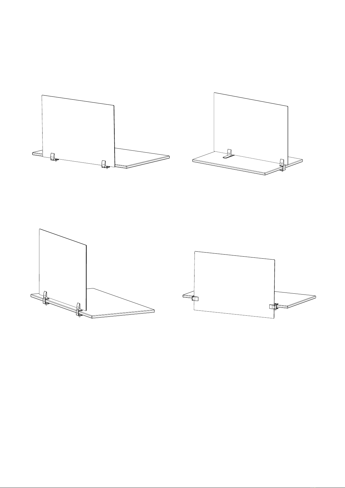
Product Installation Information
Maximum tabletop thickness = 1.25” or 34 mm
Minimum tabletop thickness = 0.25” or 6 mm
Panel Size Recommended Distance
Standard Set Up # of Mounts
18 in x 24 in 17.5 in 2
18 in x 36 in 25.5 in 2
18 in x 48 in * 19.5 in 3
18 in x 60 in * 17.5 in 4
18 in x 72 in * 21.5 in 4
24 in x 24 in 17.5 in 2
24 in x 36 in 25.5 in 2
24 in x 48 in * 19.5 in 3
24 in x 60 in * 17.5 in 4
24 in x 72 in * 21.5 in 4
Panel Size Recommended Distance
Standard Set Up # of Mounts
385 mm x 585 mm 450 mm 2
385 mm x 785 mm 650 mm 2
385 mm x 1185 mm * 500 mm 3
385 mm x 1524 mm * 450 mm 4
385 mm x 1830 mm * 550 mm 4
585 mm x 585 mm 450 mm 2
585 mm x 785 mm 650 mm 2
585 mm x 1185 mm * 500 mm 3
585 mm x 1524 mm * 450 mm 4
585 mm x 1830 mm * 550 mm 4
Note: Clamps include inlays required for
Boundri panels. Additional inlays provided
should clamps be used for alternative
panels.
* sizes not available in Privacy/Modesty set up

Doc # 100128 | Rev D | Page 3of 10
Product Conigurations
Privacy | Top Mount
Page: 6
Privacy | Modesty
Page: 8
Privacy | Back Mount
Page: 5
Side Divider | Top Mount
Page: 7

Doc # 100128 | Rev D | Page 4of 10
Materials Provided
Inlay spacers Allen wrench Bottom cover
Hole cover Table clamp screw Panel clamp screw
Clamp base Table clamp / cap cover Panel clamp
Note: Parts are not drown to scale.

Doc # 100128 | Rev D | Page 5of 10
Privacy | Back Mount
Read all assembly directions before beginning
installation.
Use all panel clamps for the required positions.
Step 1
Turn the clamp screw to be tight with the
table surface.
Step 2
Attach irst part of clamp to mount.
Step 3
Do not tighten fully to support for easier
next step.
Step 4
Insert panel. Hand tighten screw with allen
wrench until it will go no further.
Step 5
Install hole covers.

Doc # 100128 | Rev D | Page 6of 10
Privacy | Top Mount
Read all assembly directions before beginning
installation.
Use all panel clamps for the required positions.
Step 1
Turn the clamp screw to be tight with the
table surface.
Step 2
Attach irst part of clamp to mount.
Step 3
Do not tighten fully to support for easier
next step.
Step 4
Insert panel. Hand tighten screw with allen
wrench until it will go no further.
Step 5
Attach hole covers.

Doc # 100128 | Rev D | Page 7of 10
Side Divider | Top Mount
Read all assembly directions before beginning
installation.
Use all panel clamps for the required positions.
Step 1
Turn the clamp screw to be tight with the
table surface. Identify anti slip pads to be
face down.
Step 2
Attach irst part of clamp to both mounts.
Step 3
Do not tighten fully to support for easier
next step.
Step 4
Insert Panel. Hand tighten screw with allen
wrench until it will go no further.
Step 5
Attach hole covers.

Doc # 100128 | Rev D | Page 8of 10
Privacy | Modesty
Read all assembly directions before beginning
installation.
Use all panel clamps for the required positions.
This setup can only be used with the following sizes:
18” x 24”, 18” x 36”, 24” x 24”, 24” x 36” or 385 mm x
585 mm, 385 mm x 785 mm, 585 mm x 585 mm,
585 mm x 785 mm
Step 1
Turn the clamp screw to be tight with the
table surface. Identify anti slip pads to be
face down.
Step 2
Direction of clamp should be positioned to
grip the panel on left and right sides.
Step 3
Insert panel. Hand tighten screw with allen
wrench until it will go no further.
Step 4
Hand tighten screw with allen wrench until
it will go no further (right clamp).
Step 5
Attach hole covers.

Doc # 100128 | Rev D | Page 9of 10
CeramicSteel Surface: Forever warranty
PolyVision warrants that all porcelain-enameled surfaces and/or products made with
e3™ CeramicSteel (Premium Writing Surfaces) or a3™ CeramicSteel (Collaborative Products) will retain
its writing and erasing qualities and maintain its gloss variance and color consistency for the life of the
building or for as long as the product is in use, whichever comes irst.
Panel Construction and Mobile: 10 year limited warranty
PolyVision warrants that our panels, under normal atmospheric conditions and when sealed from
moisture, will not delaminate from the substrate or warp for a period of 10 years. PolyVision warrants that
our Mobile products, when used under normal conditions, will perform as intended for a period of 10
years.
Accessories: 2 year limited warranty
PolyVision warrants that our accessories, including but not limited to Collaborative ToolBar and round
magnetic eraser, when used under normal conditions will perform as intended for a period of 2 years.
Consumables like markers and chalk sticks are not covered by the Accessories warranty.
Should any failure to conform to this warranty become apparent, then, upon written notice from the
customer, PolyVision, at its option, will correct such nonconformity by repair or replacement. Correction
in the manner provided above shall constitute a fulillment of all liabilities of PolyVision with respect to
the quality of the CeramicSteel. The warranty is applicable only under normal usage and maintenance
and does not cover defects caused by improper handling, vandalism or abuse, or arising from failure to
follow PolyVision’s instructions and recommendations for maintenance.
The warranty is voided if any modiications are made to the products by the customer or other trades
with or without PolyVision’s written consent or prior knowledge. The warranty does not include the cost
of removal or reinstallation. This warranty is eective as of July 12, 2019, and supersedes the terms and
conditions of all prior surface warranties issued to the customer by PolyVision.
This limited warranty is the sole remedy for product defects and no other express or implied warranty
is provided, including but not limited to any implied warranties of merchantability or itness for a
particular purpose. PolyVision shall not be liable for consequential or incidental damages arising
from any product defect.
Collaborative Products Warranty

©2020 PolyVision Corporation. All rights reserved. Trademarks used herein are the property of PolyVision
Corporation or of their respective owner. PolyVision Corporation reserves the right to make changes
in product design, construction or detail, and to discontinue any product or material without notice.
polyvision.com 02112021
PolyVision Americas
10700 Abbotts Bridge Road
Suite 100
Johns Creek, GA 30097 USA
T 1 888 325 6351
E info@polyvision.com
PolyVision Europe
Zuiderring 56
3600 Genk, Belgium
T +32 89 32 31 30
PolyVision Asia-Pacific
15th Floor, Kinwick Centre
32 Hollywood Road, Central District
Hong Kong
T +852 2520 0160
E APA[email protected]
Table of contents
Other PolyVision Office Equipment manuals
Popular Office Equipment manuals by other brands

National Office Furniture
National Office Furniture 2513735 Assembly instruction

Formax
Formax FD 452 Operator's manual

Kimball
Kimball Xsede Assembly instructions

LDI
LDI SAFCO TAFLM48 instructions

OCEE DESIGN
OCEE DESIGN DEN.Panel Triple SASS-0068 A Assembly instructions

Steelcase
Steelcase Elective Elements Fixed Modesty Panel manual