Portwell WEBS-21B0 User manual

WEBS-21B0
Fan-less Embedded System
User's Manual
Version 1.0
Copyright © Portwell, Inc., 2017. All rights reserved.
All other brand names are registered trademarks of their respective owners.

Preface
Table of Contents
How to Use This Manual
Chapter 1 System Overview.......................................................................................................1-1
1.1 Introduction ....................................................................................................... 1-1
1.2 Check List........................................................................................................... 1-1
1.3 Product Specification........................................................................................ 1-2
1.4 Mechanical Dimension..................................................................................... 1-3
Chapter 2 System Installation....................................................................................................2-1
2.1 HDD Installation ............................................................................................... 2-1
2.2 SD card Installation........................................................................................... 2-2
2.3 mSATA Device Installation ............................................................................. 2-3
2.4 M.2 Device Installation..................................................................................... 2-3
2.5 DIN Rail Mounting Device Installation......................................................... 2-4
2.6 AT mode setting................................................................................................ 2-5
2.7 Getting Started................................................................................................... 2-5
2.8 I/O Interfaces .................................................................................................... 2-6
2.8.1 Front View................................................................................................. 2-6
2.8.2 Rear View .................................................................................................. 2-6
Chapter 3 BIOS Setup Information............................................................................................3-1
3.1 Entering Setup –Launch System Setup......................................................... 3-1
3.2 Main .................................................................................................................... 3-2
3.3 Configuration .................................................................................................... 3-3
3.4 Security ............................................................................................................. 3-20
3.5 Boot ................................................................................................................... 3-21
3.6 Exit..................................................................................................................... 3-23
Chapter 4 Important Instructions ..............................................................................................4-1
4.1 Note on the Warranty....................................................................................... 4-1
4.2 Exclusion of Accident Liability Obligation ................................................... 4-1
4.3 Liability Limitations / Exemption from the Warranty Obligation............ 4-1
4.4 Declaration of Conformity............................................................................... 4-1
Chapter 5 Frequent Asked Questions.......................................................................................5-1

Preface
How to Use This Manual
The manual describes how to configure WEBS-2190 system to meet various operating
requirements. It is divided into five chapters, with each chapter addressing a basic
concept and operation of Fan-less Embedded System.
Chapter 1: System Overview. Present what may have in the box and give an
overview of the product specifications and basic system architecture for this fan-less
embedded system.
Chapter 2: System Installation. Show the definitions and locations of all the
interfaces and describe a proper installation guide so that can easily configure the
system.
Chapter 3: BIOS Setup Information. Specify the meaning of each setup parameters,
how to get advanced BIOS performance and update new BIOS. In addition, POST
checkpoint list will give users some guidelines of trouble-shooting.
Chapter 4: Important Instructions. Indicate some instructions which must be
carefully followed when the fan-less embedded system is used.
Chapter 5: Frequent Asked Questions. Provide the answers for the most frequently
asked questions.
The content of this manual is subject to change without prior notice. These changes
will be incorporated in new editions of the document. The vendor may make
supplement or change in the products described in this document at any time.
Revision History
Revision
Date
Details of Change(s)
V1.0
2017/6/14
Initial Release

System Overview
WEB-21B0 User’s Manual 1-1
Chapter 1
System Overview
1.1 Introduction
Portwell Inc., a world-leading innovator in the Industrial PC (IPC) market,
announced WEBS-21B0, a fan-less intelligent embedded system featuring Intel®
Pentium®
/ Celeron®
Quad/ Dual-core Processor N3000 Series (codename Braswell).
Its rugged, compact design plus low power consumption make WEBS-21B0 the
perfect solution for applications in kiosk, digital signage, in-vehicle mobile video
surveillance, medical, and the harsh environments of factory automation.
The new rugged WEBS-21B0 is equipped with the Portwell NANO-6061, a
NANO-ITX embedded board based on the dual/quad-core Intel®
Celeron®/Pentium®Processor N3000 Series (4W~6W TDP), which integrates the low
power the 8th generation Intel®HD Graphics architecture that supports up to 3
displays with a maximum resolution of 4K and doubles performance compared to the
previous generation. The compact WEBS-21B0 embedded system also features
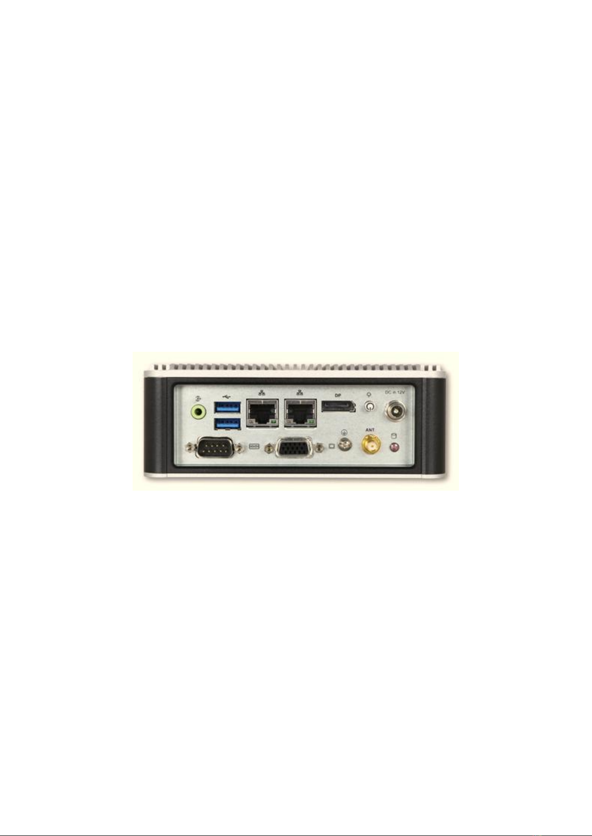
DDR3L SO-DIMM up to 8GB supporting 1333/1600 MT/s; one DisplayPort (DP) on
the rear I/O with resolution up to 3840 x 2160; one legacy VGA interface support; one
smart COM port for RS-232/422/485 selected by BIOS; and multiple storage with
2.5” HDD/SSD, mSATA as well as SD card. In addition, WEBS-21B0 is designed
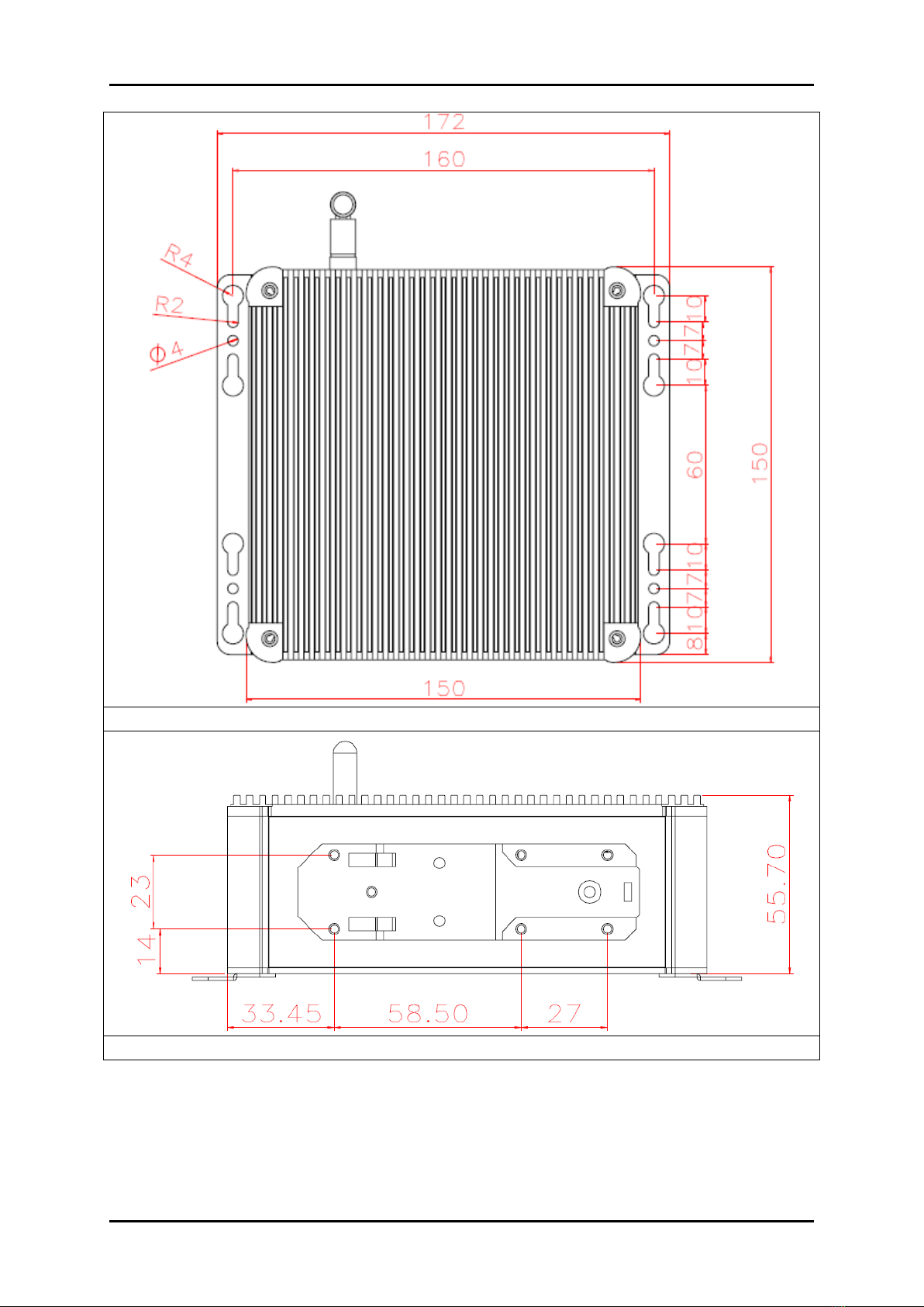
especially for IoT applications. The compact 150mm x 150mm x 50mm box integrates
the latest M.2 type E interface, which targets wireless connectivity like WIFI,
Bluetooth and near field communication (NFC) functionalities, making it an ideal
solution as an IoT gateway.
The rugged, fan-less design makes the WEBS-21B0 durable in harsh environment
applications, such as factory automation and industrial automation. The rugged and
compact WEBS-21B0 supports a temperature range from 0ºC to 50ºC for harsh
environment operations, while at the same time, its fan-less design ensures silent
operation, reliability and low maintenance rate and costs. In addition, it has already
passed a vibration test of 5Grms/ 10~500Hz and a shock test of 50G, assuring its
solidity and reliability. In addition, the system accepts 12V input voltage.
With its superior, up to quad-core processing power, high capability and excellent
3D graphics via the 8th generation Intel® HD Graphics, Portwell’s WEBS-21B0 is
indeed an ideal solution for high computing power and/or high 3D video/image
applications.
1.2 Check List
The WEBS-21B0 package should cover the following basic items:

System Overview
WEB-21B0 User’s Manual 1-2
One WEBS-21B0 Fan-less Embedded System
One 60W AC/DC Power Adapter DC-plug with screw
Other Accessories
If any of these items is damaged or missing, please contact your vendor and keep all
packing materials for future replacement and maintenance.
1.3 Product Specification
System
M/B
NANO-6061
System Chipset
Intel® Brasswell SoC
CPU
Intel®Pentium® Quad Core Processor N3710
1.6 GHz up to 2.56 GHz /4C/4T. 2M Cache.
Intel®Celeron® Quad Core Processor N3160
1.6 GHz up to 2.24 GHz /4C/4T. 2M Cache..
BIOS
AMI uEFI BIOS (SPI ROM)
System Memory
One 204-pin SO-DIMM socket supports DDR3L 1333/1600
MT/s SDRAM up to 8GB
Storage
1x 2.5”SATA HDD/SSD, 1x mSATA, 1x SD card
Watchdog Timer
Programmable by embedded controller
H/W Status Monitor
-Temperature (CPU & System)
-Voltage (CPU Vcore, 12V, 5V, 3.3V, 1.35V)
Expansion
1x M.2 socket (type E) with PCIe x 1, USB 2.0, SDIO, UART
or I2C signal
External I/O
Series Ports
1x RS-232/422/485 COM Port (selected by BIOS)
Display
1x VGA, 1x DP
USB
2x USB 3.0
Audio
Lin-out (Realtek ALC892)
LAN
2x Gigabit Ethernet (Intel® I211AT)
Other
1x Antenna hole for WIFI module
Power Supply Unit
Power Supply
DC 12V
Environment
Operating
Temperature
0℃to 55℃
Storage Temperature
-20℃to 85℃
Relative Humidity
95% @ 40℃, non-condensing
Operating Vibration
5Grms/10~500Hz, IEC 60068-2-6
Operating Shock
50G, 11 msec, IEC 60068-2-27
Mechanical
Dimension (WxDxH)
150x 150 x 56 mm; 5.9”x 5.9”x 2.1”
Weight
1.8kg
Mounting
Wall, Panel/Desk, and DIN Rail mounting

System Overview
WEB-21B0 User’s Manual 1-3
1.4 Mechanical Dimension
Front view of the WEBS-21B0 system
Rear view of the WEBS-21B0 system
Side view of the WEBS-21B0 system

System Overview
WEB-21B0 User’s Manual 1-4
Top view of the WEBS-21B0 system
Din Rail mounting view of the WEBS-21B0 system

System Installation
WEB-21B0 User’s Manual 2-1
Chapter 2
System Installation
This chapter provides you with instructions to set up your system. Definitions
and locations of all the interfaces are described so that you can easily configure
your system. For more detailed PIN assignment and jumper setting, please refer
to user’s manual of NANO-6061.
2.1 HDD Installation
It’s easy to install and maintenance the 2.5”HDD/SSD by just open the back
cover. (The height must be less than 10mm)
Step 1. Loosen the 4 screws of the back
cover
Step 2. Take out the back cover
Step 3. Loosen the 4pcs screws and take
out the HDD bracket
Step 4. Install 2.5”HDD/SSD on the
bracket with screws
M3x10L*4
Step 5. Attach HDD bracket back to
back cover and connect to SATA cable
Step 6. Tighten the 4 screws of the
back cover

System Installation
WEB-21B0 User’s Manual 2-2
2.2 SD card Installation
It’s easy to install and maintenance the SD card by just open the back cover.
Step 1. Loosen the 4 screws of the back
cover
Step 2. Take out the back cover
Step 3. Take out the side cover
Step 4. Prepare the full size SD card
Step 5. Push the full size SD card into
the socket until feel a click
Step 6. Assemble the side cover
Step 7. Position the back cover
Step 8. Tighten the 4 screws of the back
cover

System Installation
WEB-21B0 User’s Manual 2-3
2.3 mSATA Device Installation
It’s easy to install and maintenance the 1x mSATA by just open the back cover.
Step 1. Loosen the 4 screws of the back
cover
Step 2. Take out the back cover
Step 3. Assemble the mSATA card and
make sure it has been screwed
Step 4. Tighten the 4 screws of the back
cover
M2.5x6L
2.4 M.2 Device Installation
It’s easy to install and maintenance the 1x M.2 device by just open the back cover.
Step 1. Loosen the 4 screws of the back
cover
Step 2. Take out the back cover
Step 3. Assemble the M.2 WiFi card
and make sure it has been screwed
Step 4. Put the Antenna cable through
the antenna hole
M3x6L

System Installation
WEB-21B0 User’s Manual 2-4
Step 5. Install the Antenna
Step 6. Tighten the 4 screws of the back
cover
2.5 DIN Rail Mounting Device Installation
It’s easy to install and maintenance the Din Rail mounting device by just open the
back cover.
Step 1. Loosen the 4 screws of the back
cover
Step 2. Take out the back cover
Step 3. Take out the front side cover
Step 4. Prepare the Din Rail mounting
side cover
Step 5. Assemble the new side cover
with DIN Rail mounting device
Step 6. Position the back cover

System Installation
WEB-21B0 User’s Manual 2-5
Step 7. Tighten the 4 screws of the back
cover
Step 8. Clip the DIN Rail onto the
device and make sure it has been
locked tightly
2.6 AT mode setting
AT mode: Once the power supply plug in, the system starts automatically, don’t
need press the power button.
JP3 : Power On Mode Selection
#1
JP3
Function
1-2 Short
AT
2-3 Short
ATX (default)
2.7 Getting Started
It is easy to get the system started.
Step 1. Make sure the power supply
(12V) is connected properly
Step 2. Press the power button to turn
on the system

System Installation
WEB-21B0 User’s Manual 2-6
2.8 I/O Interfaces
2.8.1 Front View
2.8.2 Rear View
Power Button:
Press the power button to turn ON/OFF the system
HDD LED:
Shows real-time read and write activity of your HDD/SSD as a small blinking
indicator
DC in: (12V)
Using the provided DC source to connect to the system
Antenna Hole:
Antenna holes for M.2 WiFi card

System Installation
WEB-21B0 User’s Manual 2-7
Audio:
Connectors for Line-Out
LAN:
Two Gigabit Ethernet (10/100/1000 Mbits/sec) LAN ports by using Intel 211AT
Ethernet Controller
USB3.0
Two USB 3.0 (Universal Serial Bus) ports
VGA:
VGA –CRT display output
PIN No.
Signal Description
PIN No.
Signal Description
1
RED
2
SCL
3
GREEN
4
GND
5
BLUE
6
SDA
7
VSYNC
8
GND
9
HSYNC
10
+5V
DP:
DP (Display Port) display output
RS-232/422/485:
*Note: RS-232/422/485 configuration is determined by BIOS setting. Check BIOS
setting for details.
PIN No.
Signal Description
PIN No.
Signal Description
1
DCD#/485D-/422T-
2
RXD#/485D+/422T+
3
TXD#/422R+
4
DTR#/422R-
5
Ground
6
DSR#
7
RTS#
8
CTS#
9
RI#
10
N/C

BIOS Setup Information
WEB-21B0 User’s Manual 3-1
Chapter 3
BIOS Setup Information
WEBS-21B0 system adopts NANO-6061 mother board. The following section
describes the BIOS setup program. The BIOS setup program can be used to view
and change the BIOS settings for the module. Only experienced users should
change the default BIOS settings.
3.1 Entering Setup –Launch System Setup
Power on the computer and the system will start POST (Power On Self Test)
process. When the message below appears on the screen, press <ESC> or <DEL>
key will enter BIOS setup screen.
Press <ESC> or <DEL> to enter SETUP
If the message disappears before responding and still wish to enter Setup, please
restart the system by turning it OFF and On or pressing the RESET button. It can
be also restarted by pressing <Ctrl>, <Alt>, and <Delete> keys on keyboard
simultaneously.
Press <F1> to Run General Help or Resume
The BIOS setup program provides a General Help screen. The menu can be easily
called up from any menu by pressing <F1>. The Help screen lists all the possible
keys to use and the selections for the highlighted item. Press <Esc> to exit the
Help screen.

BIOS Setup Information
WEB-21B0 User’s Manual 3-2
3.2 Main
Use this menu for basic system configurations, such as time, date etc.
Feature
Description
Options
System Date
The date format is <Day>, <Month> <Date> <Year>. Use [+] or [-]
to configure system Date.
System Time
The time format is <Hour> <Minute> <Second>. Use [+] or [-] to
configure system Time.

BIOS Setup Information
WEB-21B0 User’s Manual 3-3
3.3 Configuration
Use this menu to set up the items of special enhanced features.
CPU Configuration
CPU Configuration Parameters

BIOS Setup Information
WEB-21B0 User’s Manual 3-4
Feature
Description
Options
Intel Virtualization
Technology
When enable, a VMM can utilize the additional hardware
capabilities provided by Vanderpool Technology
Disabled, ★
Enabled
Power Technology
(custom)
Enable the power management features
Disable, ★
Energy
Efficient,
Custom
EIST
Enable/Disable Intel SpeedStep
★Enabled,
Disabled
Turbo Mode
Turbo Mode.
★Disabled,
Enabled
CPU C6 report
Enable/ Disable CPU C6(ACPI C3) report to OS
★Enabled,
Disabled
CPU C7 report
Enable/ Disable CPU C7(ACPI C3) report to OS
★Enabled,
Disabled
DTS
Enable/Disable Digital Thermal Sensor
Enabled, ★
Disabled
Chipset Configuration
Configure Chipset feature
Feature
Description
Options
Audio Controller
Control Detection of the Azalia device.
Disable = Azalia will be unconditionally disabled.
Enable = Azaliawill be unconditionally Enable.
Disabled, ★
Enabled
Azalia HDMI Codec
Enable/Disable internal HDMI codec for Azalia
Disabled, ★
Enabled

BIOS Setup Information
WEB-21B0 User’s Manual 3-5
LAN Configuration
Configuration On Board LAN device
Feature
Description
Options
Intel Ethernet Controller WGI211AT
Enable or disable Intel Ethernet
Controller WGI211AT.
Disabled, ★Enabled
Launch Legacy PXE Rom
Launch Legacy PXE Rom.
[Disable] Not launch Rom,
[Enable] Force Launch Rom,
[Auto] Auto detect LAN Cable
status to Enable/Disable Rom
initial
★Disable, Enable, Auto
Intel Ethernet Controller WGI211AT
Enable or disable Intel Ethernet
Controller WGI211AT.
Disabled, ★Enabled
Launch Legacy PXE Rom
Launch Legacy PXE Rom.
[Disable] Not launch Rom,
[Enable] Force Launch Rom,
[Auto] Auto detect LAN Cable
status to Enable/Disable Rom
initial
★Disabled, Enabled, Auto
Wake on Lan Controller
Enable/Disable Intel Lan
WGI211AT wakeup function.
Enabled, ★Disabled

BIOS Setup Information
WEB-21B0 User’s Manual 3-6
Graphics Configuration
Configuration graphic settings
Feature
Description
Options
Force Lid Status
For test: force to set lid status as on or off.
★On, Off
PTN3460 Configuration
PTN3460 help
Table of contents
Other Portwell Industrial PC manuals
Popular Industrial PC manuals by other brands

IBASE Technology
IBASE Technology ASB200-908 user manual

Chipsee
Chipsee EPC-CM4-050 manual

Moxa Technologies
Moxa Technologies THINKCORE W345 Quick installation guide

IBASE Technology
IBASE Technology INOSP-152-RE Series user manual

Moxa Technologies
Moxa Technologies W406 WinCE user manual

Lenovo
Lenovo ThinkCentre M70c Hardware Maintenance Manual