manuals.online logo
Brands
  1. Home
  2. •
  3. Brands
  4. •
  5. VIA Technologies
  6. •
  7. Industrial PC
  8. •
  9. VIA Technologies ART-3000 User manual

VIA Technologies ART-3000 User manual

ART-3000
Quick Guide
Key Features:
• Fanless, Compact and Rugged ystem
• upport Triple Display with Dual Independent Display
• Dual Gigabit Ethernet upport
• Wide Range of Power ource
• Flexible Mounting Options
The ART-3000 is a fanless embedded system intended for various indus-
trial and embedded applications. Its based on the Em-ITX form factor and
powered by a high performance VIA Nano processor. The ART-3000’s
system is designed with rugged aluminum alloy. It features a wall/VE A/
table-mountable design for easy installation. Its also support dual-sided
multiple connectors and has a wide range DC power input supporting AT
and ATX mode.
tep 1
Remove the screws on front and rear side of the chassis.
1
tep 2
Remove the screws on right and left side of the chassis.
P/N: 99G51-012994-10
Opening the Chassis
2
Installing the Memory
tep 3
Lift up the chassis top cover.
tep 3
Unscrew the two screws to remove the memory heatsink in order to
locate the memory slot.
tep 4
Insert the memory module into the ODIMM socket at the 45 degree
angle. Then push down until the memory module snaps into place. The
ODIMM socket has two locking mechanisms that will click once the
memory module has been fully inserted.
pecifications:
• CPU: VIA Nano 1.3 GHz processor (800 MHz F B)
• System Chipset: VIA VX800 Unified Digital Media IGP
• System Memory:
• 1 x DDR2 533/667 MHz DRAM ODIMM slot
• upports memory sizes up to 2 GB
• Display: VIA Chrome™ 9 HC3 DX9 3D/2D IGP
• upports MPEG-2, H.264 and WMV9 Decoding
• upport Dual Channel 24-bit LVD panel
• Dual Independent Display
• Storage:
• 1 x 2.5-inch ATA hard disk bay
• 1 x CompactFlash disk (Type I/II) socket
• Audio: VIA VT1708B High Definition Audio Codec
• BIOS: Award BIO ( 8Mbit PI Flash )
• Front I/O:
• 2 x U B 2.0 ports
• 4 x COM ports (R -232 and R -232/422/485)
• 7V~36V DC-In power connector
• Rear I/O:
• 2 x U B 2.0
• 1 x VGA connector
• 2 x LVD connector
• 2 x RJ45 port (Gigabit Ethernet connection)
• 2 x Audio jacks (Line-out and Mic-in)
• Po er Input Voltage: DC 7V ~ 36V
• Po er Consumption: Typical 18.5 W, Max. 25.8 W
• Dimensions: 233 mm (W) x 65.2 mm (H) x 123.5 mm
(D)
• Net Weight: 1.5 Kg (3.3 lbs)
• Operating Temperature:
• With CompactFlash disk only: -20°C ~ 60°C
• With 2.5-inch hard disk drive: 0°C ~ 45°C
• Humidity: 0% ~ 90% relative humidity (non-
condensing) @ 45°C
• Vibration loading during operation:
• CompactFlash = 5Grms
• 2.5-inch hard disk drive = 1Grms
• Shock during operation:
• CompactFlash = 50G
• Hard disk drive = 20G
• EMC Approved: CE/FCC Class A
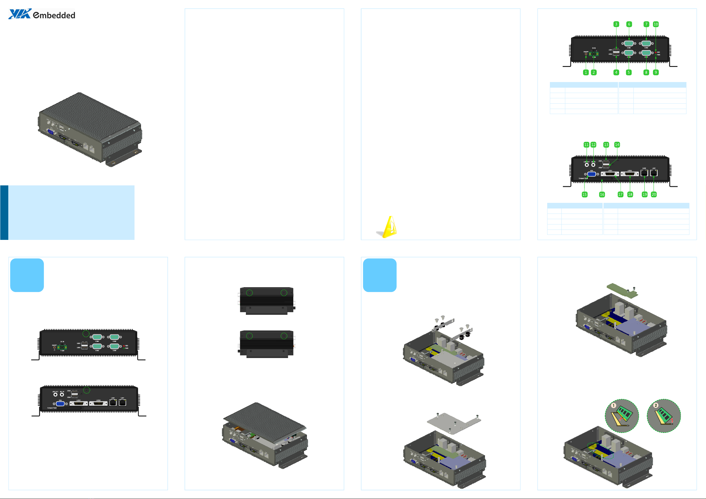
Front I/O Layout
Item Description
1 Power button (Power On/Off)
2 Power input connector
3 U B 2.0 port 1 (U B1)
4 U B 2.0 port 2 (U B2)
5 COM2 port (R -232/422/485)
Rear I/O Layout
Item Description
6 COM4 port (R -232)
7 COM3 port (R -232)
8 COM1 port (R -232/422/485)
9 Power LED indicator
10 HDD LED indicator
Item Description
11 Line-out jack
12 Mic-in jack
13 U B 2.0 port 3 (U B3)
14 U B 2.0 port 4 (U B4)
15 VGA port
Item Description
16 CompactFlash slot
17 LVD port 1 (LVD 1)
18 LVD port 2 (LVD 2)
19 RJ-45 Gigabit Ethernet LAN port 2 (LAN2)
20 RJ-45 Gigabit Ethernet LAN port 1 (LAN1)
tep 1
First remove the hard disk brackets by unscrewing the four screws.
tep 2
Unscrew the four screws in order to remove the hard disk plate to
locate the memory heatsink.
Packing List:
• 1 x ART-3000 unit
• 1 x ATA cable
• 1 x ATA power cable
• 1 x Power cable, 2-pole Phoenix plug to DC-jack
• 1 x 0.5cc Thermally Conductive Dispensable Gel in tube syringe
• 1 x Memory heatsink
Important:
Please ensure that all items in the packing list are present before
using this product. If any of the items are missing or damaged,
contact your distributor or sales representative immediately.
VIA Technologies, Inc.
1F, 531, Zhong-zheng Road,
Xindian District, New Taipei City 231,
Taiwan
Tel: 886-2-2218-5452
Fax: 886-2-2218-5453
Web: www.via.com.tw
Copyright © 2013 VIA Technologies, Inc. All rights reserved.
For more information on this and
other VIA products, please visit
www.viaembedded.com.
The mainboard in the ART-3000 system supports two ATA ports
( ATA1 & ATA2) and two 3-pin ATA power ( -Power 1 & -Power 2)
via onboard connectors. Each ATA port supports data transfer rates
up to 300MB/s enabling fast data transfer with independent DMA
operation. The ATA power connectors have 5V power source.
3
Installing the ATA
2.5-inch hard disk
4
Locating ATA and
ATA Power Ports
tep 6
Apply the thermal grease on the memory heatsink joint using the
syringe injection before placing the memory heatsink.
tep 7
Reinstall the memory heatsink cover. ecure the memory heatsink with
two screws.
tep 3
Align the mounting bracket with the mounting holes on the hard disk
plate. ecure the bracket in place with four screws. Then connect the
ATA power and data cables of the hard disk, also connect the other
ends of the cables to the ATA port and ATA power port onto the
board.
tep 1
Locate the CompactFlash access cover on the rear side of the ART-
3000 and remove the screw to remove the access cover.
tep 2
Ensure the proper orientation of CompactFlash card with the
CompactFlash slot before inserting.
tep 5
Peel the protective layers off of the memory thermal pad. Then apply
the thermal pad on the bottom of memory heatsink.
tep 1
Remove the ATA 2.5-inch hard disk mounting bracket.
tep 2
Prepare the hard disk screws and rubber washer. Align the mounting
holes on the ATA 2.5” hard disk with the mounting holes on the hard
disk mounting bracket. ecure the hard disk in place with four hard
disk screws.
Note:
Use the shorter screws when installing the brackets onto the
hard disk drive.
Note:
ATA1 & ATA2 ports can only supports 2.5-inch hard disk drive.
Important:
When connecting the ATA power cables via onboard -Power 1
and -Power 2 connectors, always make sure that the power plug
is inserted in the proper orientation and pins are properly aligned.
5 Installing the
CompactFlash Card
tep 3
Replace the CompactFlash access cover. ecure the CompactFlash
access cover with the screw.
6
Installing the
mounting Brackets
tep 1 (Default)
Prepare the left and right brackets and four screws.
tep 2
Fasten the mounting brackets, one each to the left bottom and right
bottom side of ART-3000 chassis with four screws.
tep 3 (Optional)
Position the mounting brackets on both upper sides of the chassis with
four screws.
tep 4
ecure the both mounting brackets to the wall/table with four screws.

Other manuals for ART-3000

1

Other VIA Technologies Industrial PC manuals

VIA Technologies AMOS-3003 User manual

VIA Technologies

VIA Technologies AMOS-3003 User manual

VIA Technologies AMOS-825 User manual

VIA Technologies

VIA Technologies AMOS-825 User manual

VIA Technologies EPIA-P910 User manual

VIA Technologies

VIA Technologies EPIA-P910 User manual

VIA Technologies AMOS-820 SKU User manual

VIA Technologies

VIA Technologies AMOS-820 SKU User manual

VIA Technologies AMOS-3007 User manual

VIA Technologies

VIA Technologies AMOS-3007 User manual

VIA Technologies AMOS-3005 User manual

VIA Technologies

VIA Technologies AMOS-3005 User manual

VIA Technologies AMOS-3006 User manual

VIA Technologies

VIA Technologies AMOS-3006 User manual

VIA Technologies AMOS-3000 User manual

VIA Technologies

VIA Technologies AMOS-3000 User manual

VIA Technologies AMOS-820-QP SKU User manual

VIA Technologies

VIA Technologies AMOS-820-QP SKU User manual

VIA Technologies AMOS-825 User manual

VIA Technologies

VIA Technologies AMOS-825 User manual

VIA Technologies AMOS-5210 User manual

VIA Technologies

VIA Technologies AMOS-5210 User manual

VIA Technologies ART-3000 User manual

VIA Technologies

VIA Technologies ART-3000 User manual

VIA Technologies AMOS-5002 User manual

VIA Technologies

VIA Technologies AMOS-5002 User manual

Popular Industrial PC manuals by other brands

National Instruments PXI-8150 Series Getting started

National Instruments

National Instruments PXI-8150 Series Getting started

Siemens SIMATIC IPC847C Getting started

Siemens

Siemens SIMATIC IPC847C Getting started

JHCTech BRAV-7302 user manual

JHCTech

JHCTech BRAV-7302 user manual

MSI MS-9A69-U Series manual

MSI

MSI MS-9A69-U Series manual

Moxa Technologies DA-662A-8 Hardware user manual

Moxa Technologies

Moxa Technologies DA-662A-8 Hardware user manual

IEI Technology HTB-210-Q470 user manual

IEI Technology

IEI Technology HTB-210-Q470 user manual

EverFocus eNVP-JNX-AI-D0000 user manual

EverFocus

EverFocus eNVP-JNX-AI-D0000 user manual

MSI MS-9A97 manual

MSI

MSI MS-9A97 manual

AXIOMTEK tBOX510-518-FL-24-110MRDC user manual

AXIOMTEK

AXIOMTEK tBOX510-518-FL-24-110MRDC user manual

adstec OPC7000 Series instruction manual

adstec

adstec OPC7000 Series instruction manual

ASROCK iBOX-1185G7E Technical reference

ASROCK

ASROCK iBOX-1185G7E Technical reference

AXIOMTEK EBOX640-500-FL Series user manual

AXIOMTEK

AXIOMTEK EBOX640-500-FL Series user manual

Neousys Technology Nuvo-6108GC Series user manual

Neousys Technology

Neousys Technology Nuvo-6108GC Series user manual

Chipsee PPC-A72-156-P instruction manual

Chipsee

Chipsee PPC-A72-156-P instruction manual

GIGAIPC QBiX-Pro-TGLA1115G4EH-A1 quick start guide

GIGAIPC

GIGAIPC QBiX-Pro-TGLA1115G4EH-A1 quick start guide

DMP Electronics EBOX-333 Series user guide

DMP Electronics

DMP Electronics EBOX-333 Series user guide

Lanner LEC-2137B user manual

Lanner

Lanner LEC-2137B user manual

IEI Technology HTB-200-C236 user manual

IEI Technology

IEI Technology HTB-200-C236 user manual

manuals.online logo
manuals.online logoBrands
  • About & Mission
  • Contact us
  • Privacy Policy
  • Terms and Conditions

Copyright 2025 Manuals.Online. All Rights Reserved.