Strobe device has only one mounting orientation. LED light element should be oriented toward the floor
The 110/177 candela strobe is Listed for use in sleeping or non-sleeping areas when installed in accordance with appropriate NFPA
Standards and the Authority Having Jurisdiction.
NFPA 72/ANSI 117.1 provide means for determining equivalent illumination using fewer, higher intensity strobes within the same protected
area.
Application Notes: T3/T4 Operation with Wheelock Sync
T3/T4 Sync Selectable operationrequires Wheelock Sync (using Silence/Resound Commands). All appliances must be set to T3/T4. Code
4 (T4) operation occurs with Wheelock Sync Resound Mode (No Silence). Code 3 (T3) operation occurs with Wheelock Sync Silence Mode
(Audible Silence function is available only when using Continuous or T3 setting). A Wheelock DSM-12/24-R sync module may be used to
facilitate T3/T4 operation.
All installations shall be in accordance with:
1) In the United States, the National Electrical Code, NFPA 70, and the National Fire Alarm and Signaling Code, NFPA 72.
2) In Canada, CSA C22.1, Canadian Electrical Code, Part I, Safety Standard for Electrical Installations, Section 32; and the Canadian
Standard for the Installation of Fire Alarm Systems - CAN/ULC-S524.
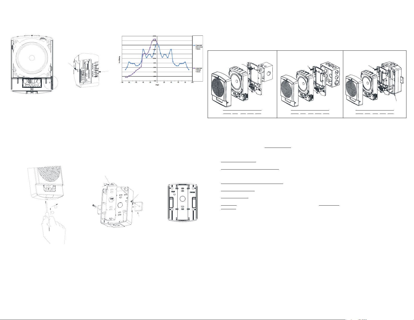
MOUNTING PROCEDURES:
1. Select a mounting option and install the backbox. Surface back box requires 5 1/8” spacing for surface mounting. Screws are
provided. Conduit entrances to the backbox should be selected to provide sufficient wiring clearance for the installed product. Do
not pass additional wires (used for other than the signaling appliance) through the backbox. Such additional wires could result in
insufficient wiring space for the signaling appliance.
2. Install the Mounting Plate on the backbox with “TOP” facing up. Use 6-32 screws for Single/Double Gang back-box, 8-32 screws for
4” back-box or hi-lo screws for the surface back box.
3. Pre-Wire: Connect field wires to terminals on mounting plate (reference Figure 1 and 2). Use care and proper techniques to position
the field wires in the backbox so that they use minimum space and produce minimum stress on the product. This is especially
important for stiff, heavy gauge wires and wires with thick insulation or sheathing. When terminating field wires, do not use more
lead length than required. Excess lead length could result in insufficient wiring space for the signaling appliance.
4. Pre-Test: Mounting Plate contains a SHUNT between adjacent “+” terminals to facilittate testing before device is attached.
Note: Shunt will open permanently when device is installed on mounting plate.
5. Verify appliance settings are correct for your application. Settings are shown in Figure 3. Factory settings is Code 3 (T3), and 110cd.
Use Code 3 (T3) for fire emergency only, and Code 4 (T4) for carbon monoxide (CO) emergency only.
6. Place the appliance over the mounting plate. Engage TOP hook on mounting plate, then secure with screw at the bottom. Use care
to prevent speaker cone damage when driving the screw.
7. Align cover to the appliance with strobe opening over LED lens. Then, snap the cover in place.
8. To remove the appliance, insert a small flat-bladed screwdriver into the bottom opening ½” as shown in Figure 5. Then lift off grille.
Important: Do not fully back out terminal screws. Do not over tighten screws or terminals. Excessive torque may affect
operation. When using power tools, ensure the torque is set to the lowest setting available.
NOTE: Final acceptance is subject to Authorities Having Jurisdiction.
Check the installation instructions of the manufacturers of other equipment used in the system for any guidelines or restrictions on wiring
and/or locating Notification ApplianceCircuits (NAC) and notification appliances. Some system communication circuits and/or audio circuits,
for example, may require special precautions to assure immunity from electrical noise (e.g. audio crosstalk).
This equipment has been tested and found to comply with the limits for a Class A digital device, pursuant to part 15 of the FCC Rules.
These limits are designed to provide reasonable protection against harmful interference when the equipment is operated in a commercial
environment. This equipment generates, uses, and can radiate radio frequency energy and, if not installed and used in accordance with
the instruction manual, may cause harmful interference to radio communications. Operation of this equipment in a residential area is likely
to cause harmful interference in which case the user will be required to correct the interference at his own expense.
This Class A digital apparatus meets all requirements of the Canadian Interference-Causing Equipment Regulations. Cet appareil
numérique de la classe A respecte toutes les exigences du Réglement sur le matériel brouilleur du Canada.
Any material extrapolated from this document or from Potter manuals or other documents describing the product for use in promotional or
advertising claims, or for any other use,including description of the product’s application, operation, installation and testing is used at the
sole risk of the user and Potter will not have any liability for such use. IN NO CASE WILL SELLER’S LIABILITY EXCEED THE PURCHASE
PRICE PAID FOR A PRODUCT.
6/23