Power Innovations EVQC060-35 User manual

EV Quick Charger – DC 60 kW
Model EVQC060-35
Installation and Operation Manual
MNL213
Revision 1.0

ii |
MNL213 Revision 1.0 7/7/2023
READ THIS MANUAL CAREFULLY
SAVE ALL INSTRUCTIONS
This manual contains important information regarding Power Innovations International products or processes listed on the
title page. Please read all instructions carefully before assembling, installing, or operating equipment. Keep this manual
handy for easy reference.
This manual may accompany other instructional guides or manuals for standard installation and operations of the
supported products. Please contact Power Innovations if you need additional guides or manuals and have not received
them.
Product names mentioned herein may be trademarks (™) and/or registered trademarks (®) of their respective companies,
which may include Power Innovations International, Inc. (part of LiteOn Group), LiteOn Technology Corporation, or a third
party.
Copyright © 2023
Power Innovations International, Inc.; American Fork, UT, USA
All rights reserved.

MNL213 Revision 1.0 7/7/2023
| iii
Contents
1—Product Overview...........................................................................................................................................................1
1.1 Introduction...............................................................................................................................................................1
1.2 Highlighted Features.................................................................................................................................................1
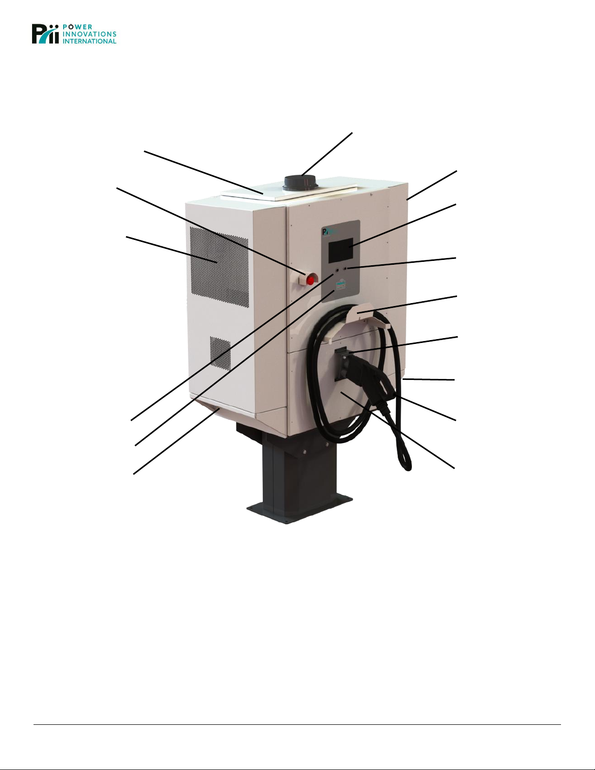
1.3 Charger Features Identified......................................................................................................................................2
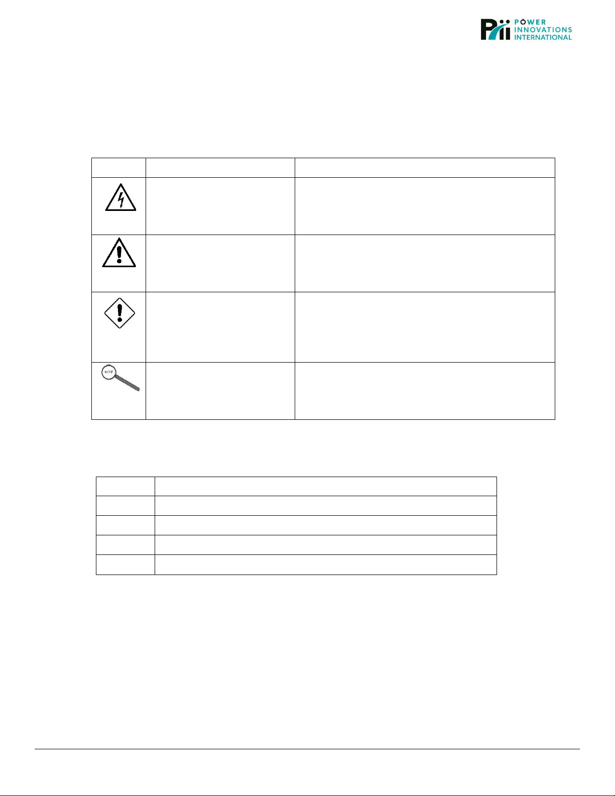
1.4 Symbols Used in this Manual ...................................................................................................................................3
1.5 Acronyms Used in this Manual.................................................................................................................................3
2—Safety and Specifications..............................................................................................................................................4
2.1 IMPORTANT SAFETY INSTRUCTIONS –SAVE THESE INSTRUCTIONS ..........................................................4
2.2 Specifications - EV Quick Charger Model EVQC060-35..........................................................................................5
3—Installing EV Charger .....................................................................................................................................................6
3.1 What’s Provided with Charger ..................................................................................................................................6
3.2 What’s in Pedestal Kit (Required Base for Charger) ................................................................................................6
3.3 Additional Tools and Supplies Required...................................................................................................................6
3.4 Prepare Installation Site............................................................................................................................................7
3.5 Mount Pedestal on Concrete Pad or Driveway ........................................................................................................9
3.7 Install Power Supply Units and Shelf Controllers...................................................................................................12
3.8 Configure Cellular Modem and Registering Charger on Network..........................................................................14
3.9 Configure and Wire AC Input Power ......................................................................................................................15
4—Operating EV Quick Charger.......................................................................................................................................18
5—Maintaining EV Charger...............................................................................................................................................20
5.1 Clean Air Vents.......................................................................................................................................................20
5.2 Restart after Emergency Stop ................................................................................................................................20
5.3 Replace Surge Modules in Surge Protective Device..............................................................................................20
6—Regulatory.....................................................................................................................................................................21
7—Warranty........................................................................................................................................................................21
8—Contact Information .....................................................................................................................................................22

iv |
MNL213 Revision 1.0 7/7/2023
This page left blank intentionally.

MNL213 Revision 1.0 7/7/2023
| 1
1—Product Overview
This section provides product overview for EVQC060-35, Power Innovations DC 60 kW Quick Charger.
1.1 Introduction
This quick charger is an all-in-one electric vehicle (EV) power supply and charging authorization terminal. Once
installed and operational, an operator can plug the EV charging cable into their electric vehicle, use an RFID payment
card to tap on, be authorized by the system, and start a charging session.
Although some assembly is required, each 60 kW quick charger ships with all parts required for installation except the
electrical conduit and wires (provided by installer). The supported mounting solution is a kit that includes a steel
pedestal that mounts on a concrete pad or driveway. A pedestal kit for each 60 kW quick charger ordered Is included
by default in the order.
Use this document to help you:
1. Safely prepare installation site
2. Mount pedestal
3. Attach charger to pedestal
4. Install power modules and shelf controllers
5. Configure cellular modem and register charger on network
6. Configure and wire AC input power to quick charger
7. Operate EV quick charger (Charge an electric vehicle)
8. Maintain EV quick charger
1.2 Highlighted Features
Feature
Description
AC Input Power
Options
240V
208/240V 3-phase, 4-wire Delta
480V 3-phase, 5-wire Wye
DC Output Power
60 kW
Communication
Cellular 4G LTE Network, Wi-Fi
User Interface
Emergency Stop Button
LCD Screen
RFID Tap payment
Cancel button
Accept button
Mounting Solution
EVQC060-PEDP Pedestal Kit (sold separately): Includes a powder-coated
steel pedestal that mounts on a 4 inch or thicker concrete pad or driveway.

2 |
MNL213 Revision 1.0 7/7/2023
1.3 Charger Features Identified
Cellular Antenna
Top Panel
Cooling Fans
Emergency
Stop Button
User Interface
LCD Screen
Cooling Fans
ACCEPT Button
Cable Hanger
CANCEL Button
RFID Card Reader
Handhold
Plug Holster
Handhold
CCS1
Charging Cable
AC Service Panel
Figure 1—EV Quick Charger Model EVQC060-35

MNL213 Revision 1.0 7/7/2023
| 3
1.4 Symbols Used in this Manual
Icons or symbols are occasionally used throughout this manual to help identify safety warnings and other
pertinent content contained here. These icons are described in the table below.
Icon
Type of Warning
Description
ELECTRICAL WARNINGS
WARNING! RISK OF ELECTRIC SHOCK!
ADDITIONAL TEXT THAT FOLLOWS THIS SYMBOL
PROVIDES MORE INFORMATION ABOUT THE
SPECIFIC WARNING.
WARNINGS
WARNING! RISK OF ELECTRIC SHOCK!
ADDITIONAL TEXT THAT FOLLOWS THIS SYMBOL
PROVIDES MORE INFORMATION ABOUT THE
SPECIFIC WARNING.
Caution!
Caution!
Indicates a potentially hazardous situation which, if not
avoided, can result in minor to moderate injury, or
serious damage to the equipment. Important safety
measures may also be described in Cautions.
Note
Note
Offers practical advice that may be helpful but can be
disregarded.
1.5 Acronyms Used in this Manual
Acronym
Explanation
AC
Alternating Current
ADA
American Disabilities Act
DC
Direct Current
EV
Electric Vehicle

4 |
MNL213 Revision 1.0 7/7/2023
2—Safety and Specifications
The following safety instructions apply throughout the EV Charger installation process. Be familiar with them
before moving on to the next section to complete the installation.
2.1 IMPORTANT SAFETY INSTRUCTIONS –SAVE THESE INSTRUCTIONS
ELECTRICAL WARNINGS –WARNING! RISK OF ELECTRIC SHOCK!
WARNING! RISK OF ELECTRIC SHOCK!
ONLY QUALIFIED ELECTRICAL PERSONNEL FAMILIAR WITH THE CONSTUCTION AND
OPERATION OF THIS TYPE OF EQUIPMENT AND THE HAZARDS INVOLVED SHOULD
ADJUST, MODIFY, AND SERVICE THIS EQUIPMENT. FAILURE TO OBSERVE THIS
PRECAUTION COULD RESULT IN SEVERE INJURY OR DEATH.
WARNING! RISK OF ELECTRIC SHOCK!
READ THIS MANUAL THOROUGHLY PRIOR TO INSTALLING AND ENERGIZING THE
EQUIPMENT. INSPECTION AND MAINTENENACE OF THIS EQUIPMENT SHOULD BE
PERFORMED IN ACCORDANCE WITH THE PROCEDURES DETAILED IN THIS MANUAL.
WARNING! RISK OF ELECTRIC SHOCK!
THIS UNIT CONTAINS NO INTERIOR PARTS THAT CAN BE SERVICED WITHOUT QUALIFIED
PERSONNEL. IF MAINTENANCE PROCESSES SPECIFIED IN THIS MANUAL FAIL TO SOLVE
THE PROBLEM, QUALIFIED PERSONNEL MUST SERVICE THE UNIT.
WARNING! RISK OF ELECTRIC SHOCK!
THE PURPOSE OF THIS MANUAL IS TO PROVIDE YOU WITH INFORMATION NECESSARY TO
SAFELY INSTALL, OPERATE, AND MAINTAIN THIS EQUIPMENT. KEEP THIS MANUAL FOR
FUTURE REFERENCE.
WARNING! RISK OF ELECTRIC SHOCK!
SHUT OFF POWER SUPPLY BEFORE BEGINNING INSTALLATION ACTIVITIES OR
MAINTENANCE WORK. FAILURE TO OBSERVE THIS PRECAUTION COULD RESULT IN
SEVERE INJURY OR DEATH.
WARNING! RISK OF ELECTRIC SHOCK!
THIS EV QUICK CHARGER CONTAINS HIGH VOLTAGE POWER THAT IS POTENTIALLY
DANGEROUS IF NOT HANDLED PROPERLY.
Caution!
The installer is responsible for conforming to all local and national electrical codes and
standards applicable in the jurisdiction this equipment is installed in.

MNL213 Revision 1.0 7/7/2023
| 5
2.2 Specifications - EV Quick Charger Model EVQC060-35
Electrical Specifications
AC Input
AC Input Power Options
240V single phase
208V/240V 3-phase, 4-wire Delta
480V 3-phase, 5-wire Wye
AC Input Voltage Operating Range and
Current
240V single phase: 190V to 305V, 150A max
208V/240V 3 phase Delta: 190V to 264V, 86A max
480V 3 phase Wye: 384V to 528V, 50A max
Recommended upstream overcurrent
protection device rating
240V single phase: 200A
208V/240V 3 phase Delta: 110A
480V 3 phase Wye: 80A
Power factor
> 0.98
Efficiency
> 95% @ full load
DC Output
Maximum DC Output Power
60 kW
DC Output Voltage Range
250V –920V (400V and 800V nominal)
Maximum DC Output Current
75A with DC output < 450V
38A with DC output > 450V
DC Connector
CCS1
DC Charging Cable Length
5 m (16.4 ft.) standard
Dimensions and Weights
Dimensions (H x W x D) –
EV Charger with pedestal
1605 x 997 x 650 mm
(63.2 x 39.2 x 25.4 in.)
Dimensions Pedestal Baseplate (W x D)
457 x 286 mm (18 x 11.3 in)
Dimensions Mounting hole pattern (W x D)
415 x 244 mm (16.4 in. x 9.6 in.)
Weight –60 kW EV Charger
260.8 kg (575 lbs.)
Weight –Pedestal for 60 kW EV Charger
24.5 kg (54 lbs.)
Environment Specification
Operating Temperature Range
-35°C to +50°C
Storage Temperature Range
-40°C to +80°C
Ingression Protection of Enclosure
IP54, NEMA 3S
Humidity
95%
Altitude - Operation
3000 m (9845 ft.)
Certificate/Compliance
Complies with UL Standards for Safety
UL 2202: Electric Vehicle (EV) Charging System Equipment
UL 2231-1: Personnel Protection Systems for Electric
Vehicle (EV) Supply Circuits; Part 1: General Requirements

6 |
MNL213 Revision 1.0 7/7/2023
3—Installing EV Charger
ELECTRICAL WARNINGS –WARNING! RISK OF ELECTRIC SHOCK!
WARNING! RISK OF ELECTRIC SHOCK! SHUT OFF POWER SUPPLY BEFORE BEGINNING
INSTALLATION ACTIVITIES AND BEFORE REMOVING EV QUICK CHARGER’S AC SERVICE PANEL
FOR ANY INSTALLATION OR MAINTENANCE WORK. FAILURE TO OBSERVE THIS PRECAUTION
COULD RESULT IN SEVERE INJURY OR DEATH.
WARNING! RISK OF ELECTRIC SHOCK! ONLY QUALIFIED ELECTRICAL PERSONNEL FAMILIAR
WITH THE CONSTUCTION AND OPERATION OF THIS TYPE OF EQUIPMENT AND THE HAZARDS
INVOLVED SHOULD ADJUST, MODIFY, AND SERVICE THIS EQUIPMENT. FAILURE TO OBSERVE
THIS PRECAUTION COULD RESULT IN SEVERE INJURY OR DEATH.
WARNING! RISK OF ELECTRIC SHOCK! DO NOT CONNECT POWER SUPPLY TO THE EV QUICK
CHARGER UNTIL THE WIRING AND BUS BAR CONFIGURATION IS COMPLETE AND THE AC
SERVICE PANEL IS IN PLACE AND SECURE.
3.1 What’s Provided with Charger
P/N
Description
EVQC060-35
1 EV Quick Charger for DC 60kW output, fully assembled exterior
6 Shelf Controllers (SCs)
18 Power Supply Units (PSUs)
3 Bus Bars, each uniquely configured
6 Socket Head Cap Screws, M6 x 14 mm long
4 Socket Head Cap Screws, M8 x 16 mm long
MNL213
“EV Quick Charger –DC 60 kW Model EVQC060-35, Installation and Operation
Manual” (this document)
3.2 What’s in Pedestal Kit (Required Base for Charger)
P/N
Description
EVQC060-PEDP
Pedestal Kit for EVQC060-35, includes: pedestal; 4, ½” diameter, concrete
wedge anchors; 2 mounting plates; 8 sets of M10 x 20 mm long socket button-
head bolt, split washer, and flat washer; 4 sets of M12 hex nut, split washer, flat
washer, and silicone rubber washer; square, self-adhesive rubber gasket;
square metal plate; 8 sets of M5 wingnut, split washer, flat washer, and silicone
washer; and 4 plastic plugs.
3.3 Additional Tools and Supplies Required
•Level
•Pencil
•Tape measure
•Philips Screwdriver
•Metric Allen
wrench set
•Hand Drill
•Electrical
Conduit and
Wires

MNL213 Revision 1.0 7/7/2023
| 7
3.4 Prepare Installation Site
1. Become familiar with essential dimensions of EV Quick Charger EVQC060-35 and pedestal as shown in
Figure 2.1, 2.2, and 2.3.
Figure 2.1—Height and Width of 60kW Charger and Pedestal Figure 2.2—Depth of 60kW Charger and Pedestal
Figure 2.3—Dimensions of Pedestal Baseplate

8 |
MNL213 Revision 1.0 7/7/2023
2. Best practices for pedestal-mounted chargers installation
locations:
(a) Select location where charger will not be in direct sunlight.
(b) Pedestal should be mounted on a concrete pad or driveway
that is 4 inches thick or thicker. The wedge anchors will secure
the charger to the concrete when the anchors are installed to a
depth of 2.25 inches (Figure 3).
Figure 3—Wedge anchors secure Pedestal
when installed in concrete 2.25 inches.
(c) When laying out placement, ensure minimum space between chargers will be 914 mm (36 in.) to help
ensure good air flow and user accessibility around charger (Figure 4).
Figure 4—914 mm (36 in.) Minimum space between chargers
(d) If laying out placement using a pedestal baseplate template, have center of two baseplates be at least
1910 mm (72.5 in.) apart (Figure 5) and then mark the floor or ground.
Figure 5—1910 mm (75.2 in.) Minimum space between pedestal baseplate centers

MNL213 Revision 1.0 7/7/2023
| 9
3.5 Mount Pedestal on Concrete Pad or Driveway
Note: When mounting charger, be sure to follow spacing recommendations provided in this manual to comply
with the guidelines outlined in the American Disability Act (ADA).
1. Route AC power cables up through concrete pad or driveway at center mark for pedestal baseplate, then
route cable up center of unmounted pedestal (Figure 6).
Figure 6—AC power cables routed out of concrete
2. Align pedestal’s baseplate with planned installation location, then secure pedestal to concrete using 4 wedge
anchors provided and install them at least 2.25 inches (Figure 7).
Figure 7—Anchor Pedestal to concrete
3. Attached mounting plate to front and back of pedestal using 8 sets of M10 socket button-head bolt, split
washer, and flat waster provided (Figure 8).
Figure 8—Attaching Pedestal’s mounting plates

10 |
MNL213 Revision 1.0 7/7/2023
3.6 Attach Charger to Pedestal
ELECTRICAL WARNINGS –WARNING! RISK OF ELECTRIC SHOCK!
WARNING! RISK OF ELECTRIC SHOCK! SHUT OFF POWER SUPPLY BEFORE BEGINNING
INSTALLATION ACTIVITIES AND BEFORE REMOVING EV QUICK CHARGER’S AC SERVICE PANEL
FOR ANY INSTALLATION ACTIVITY. FAILURE TO OBSERVE THIS PRECAUTION COULD RESULT IN
SEVERE INJURY OR DEATH.
WARNING! RISK OF ELECTRIC SHOCK! DO NOT PROVIDE LIVE POWER TO THE EV QUICK
CHARGER UNTIL THE WIRING AND BUS BAR CONFIGURATION IS COMPLETE AND THE AC
SERVICE PANEL IS IN PLACE AND SECURE.
Caution! - This EV quick charger weighs approximately 260.8 kg (575 lbs.) without
its pedestal. To help avoid injury, use lift supports, such as a weight belt, lifting
partner, or jack, when lifting and setting the charger onto the pedestal studs.
1. On uninstalled charger, open AC Service Panel by removing all screws around
panel’s perimeter (Figure 9).
Figure 9
2. Use the 4 installed eye bolts (Figure 10), straps, and other lift
supports, such as crane, jack, weight belt, lifting partner, and
handholds to safely lift the charger.
Note: Straps used should be in-line with the eye bolts.
Figure 10
3. Feed AC power cable into bottom of charger, then lower
charger mounting holes onto four pedestal studs (Figure 11).
4. In bottom corners of charger, secure charger to pedestal using four sets of
M12 x 20 mm long hex-head bolt, split washer, flat washer, and silicone
rubber washers provided (Figure 12); Tighten bolts to 780 in.-lbs. (90 n-m)
torque.
5. Remove eyebolts and replace with the 4 plastic plugs provided.
Figure 11
Figure 12

MNL213 Revision 1.0 7/7/2023
| 11
6. Remove paper from self-adhesive square rubber gasket and place adhesive side down inside charger as
shown in Figure 14 (inside small studs).
Figure 13—Square Rubber Gasket
Figure 14—Placement of Square Rubber Gasket inside bottom of charger
7. Ensure center hole in square plate (Figure 15) is large enough to feed AC power cord through. If you need to
enlarge the hole, do so outside of and away from the charger.
Figure 15—Square Metal Plate
Figure 16—Placement of Metal Plate inside bottom of charger
8. Feed AC power in cable through square metal plate, lower plate on top of square rubber gasket and on to the
8 small studs (Figure 16), and then secure the plate with the 8 sets of M5 wingnut, split washer, flat washer,
and silicone washer.

12 |
MNL213 Revision 1.0 7/7/2023
3.7 Install Power Supply Units and Shelf Controllers
ELECTRICAL WARNINGS –WARNING! RISK OF ELECTRIC SHOCK!
WARNING! RISK OF ELECTRIC SHOCK!
ENSURE POWER SUPPLY IS SHUT OFF BEFORE STARTING OR CONTINUING INSTALLATION
ACTIVITIES AND BEFORE OPENING EV QUICK CHARGER’S TOP PANEL. FAILURE TO OBSERVE
THIS PRECAUTION COULD RESULT IN SEVERE INJURY OR DEATH.
This EV Quick Charger ships with many of its components pre-installed, such as cellular antenna, CCS1
charging cable, and empty power shelves. Essential charger components that do not ship preinstalled are
shelf controllers (SCs) and power supply units (PSUs). These can be installed anytime and in any order prior
to powering the charger on.
Note: We recommend you first mount the wall-mount bracket or pedestal (section 3.5) and then secure
charger to bracket or pedestal (section 3.6) BEFORE you install the SCs and PSUs. This will lessen the
weight of the charger while it is being lifted and attached.
To install shelf controllers and power supply units:
1. Ensure AC power to EV Quick charger is turned OFF either at site’s AC breaker or charger’s AC main
switch behind AC Service Panel.
2. Open EV charger’s Top Panel (Figure 17) by removing screws around perimeter (keeping cellular
antenna attached) and then set top panel and screws aside.
Figure 17—Remove screws around Top Panel to open

MNL213 Revision 1.0 7/7/2023
| 13
3. Insert 6 Shelf Controllers (SCs), 1 on each shelf (Figure 18.1) and secure with built-in screw (Figure
18.2).
Figure 18.1—Install Shelf Controllers Figure 18.2—Secure Shelf Controllers
4. Insert 18 power supply units (PSUs), 3 on each shelf (Figure 19).
5. (Optional) To configure cellular modem now, leave top panel open and skip to next section.
6. Return Top Panel to top of charger and secure with its original screws.
Shelf Controller Power Supply Units
Figure 19—Install Power Supply Units

14 |
MNL213 Revision 1.0 7/7/2023
3.8 Configure Cellular Modem and Registering Charger on Network
WARNING! RISK OF ELECTRIC SHOCK!
DO NOT CONNECT POWER SUPPLY TO EV QUICK CHARGER UNTIL SIM CARDS ARE INSERTED
INTO CELLULAR MODEM AND TOP PANEL COVER AND SCREWS ARE REINSTATED.
Note: SIM cards for cellular modem must be provided by product owner or administrator.
To configure cellular modem and register charger on the backend network:
1. Ensure AC power to EV Quick charger is turned OFF either at site’s AC breaker or charger’s AC main
switch behind AC Service Panel.
2. If EV charger’s Top Panel is closed, open it by removing screws around perimeter (keeping cellular
antenna attached) and then set top panel and screws aside (Figure 20).
Figure 20—Remove Top Panel to access cellular modem
3. Inside open top of charger, remove two screws from face of cellular modem and remove slot cover to
expose modem’s expansion slots -- one for a memory card and two for SIM cards (Figure 21).
A B
Figure 21—Expose SIM card slots in cellular modem
4. Insert a SIM card in slot A or slot B.
5. Return slot cover to its original position on modem and secure it with the two original screws.
6. Return Top Panel to top of charger and secure with its original screws.
7. Register this EV charger as one of the supported devices on the owner’s backend network. Later, after
you have configured and wired the AC power input and you apply power to the charger, the modem will
find the cellular network and attempt to automatically connect.
8. Continue to next section to configure and wire AC input power.

MNL213 Revision 1.0 7/7/2023
| 15
3.9 Configure and Wire AC Input Power
ELECTRICAL WARNINGS –WARNING! RISK OF ELECTRIC SHOCK!
WARNING! RISK OF ELECTRIC SHOCK!
SHUT OFF POWER SUPPLY BEFORE BEGINNING INSTALLATION ACTIVITIES. FAILURE TO
OBSERVE THIS PRECAUTION COULD RESULT IN SEVERE INJURY OR DEATH.
WARNING! RISK OF ELECTRIC SHOCK!
DO NOT PROVIDE LIVE POWER TO THE EV QUICK CHARGER UNTIL BUS BAR CONFIGURATION
AND AC WIRING IS COMPLETE AND THE AC SERVICE PANEL IS IN PLACE AND SECURE.
WARNING! RISK OF ELECTRIC SHOCK!
ONLY QUALIFIED ELECTRICAL PERSONNEL FAMILIAR WITH THE CONSTUCTION AND OPERATION
OF THIS TYPE OF EQUIPMENT AND THE HAZARDS INVOLVED SHOULD ADJUST, MODIFY, AND
SERVICE THIS EQUIPMENT. FAILURE TO OBSERVE THIS PRECAUTION COULD RESULT IN SEVERE
INJURY OR DEATH.
1. Ensure AC power to EV quick charger is turned OFF either at site’s AC breaker or charger’s AC main switch.
2. If AC Service Panel is closed, open it by removing all screws on the panel’s perimeter (see Figure 22).
Figure 22—Opening AC Service Panel by removing screws around panel’s perimeter

16 |
MNL213 Revision 1.0 7/7/2023
3. Determine which of the three supported configurations is required for this installation
240V (single-phase): Line, Neutral, Ground
208V/240V 3-phase, 4-wire Delta: Line 1, Line 2, Line 3, Ground
480V 3-phase, 5-wire WYE: Line 1, Line 2, Line 3, Neutral, Ground
4. In a bag that ships with charger, locate configuration Bus Bars (illustrated in Figure 23) and the socket-head
cap screws for installing one of them.
240 V (single phase)
208/240 V 3-phase,
4-wire Delta
480 V 3-phase,
5-wire WYE
BACK
FRONT
Figure 23—Bus Bar to install for each supported AC Input Power Configuration
5. Install the configuration Bus Bar required for this charger’s AC input power (example shown in Figure 24)and
then secure the Bus Bar to the charger using 6 upper socket head cap screws (M6 x 14 mm long) and 4 lower
socket head cap screws (M8 x 16 mm long).
Figure 24—Example: Before and after installing the Bus Bar for 480V 3-phase, 5-wire Wye
Table of contents
Other Power Innovations Batteries Charger manuals