Power Products ST-375 User manual

1 SEPTEMBER 2005
POWER PRODUCTS MANUAL No. 375-905-2
TECHNICAL MANUAL
INSTRUMENT VERIFICATION PROCEDURE
HIGH RATE DISCHARGE TESTER
POWER PRODUCTS
P/N 37512 MODEL ST-375
MFD BY: POWER PRODUCTS INC
27PAMARON WAY STE E
NOVATO, CA 94949
CAGE CODE 3C8X4
www.power-products.com
POC PAUL CHAIT

TABLE OF CONTENTS
Section Page
1 Introduction and Description 1
2 Equipment Requirements 2
3 Preliminary Operations 2
4 VerificationProcess 2-4
ILLUSTRATIONS
Figure Page
1 VoltmeterTestSetup 3
2 AmmeterTestSetup 3
3 TimingSetupTest 5
- Data Sheet 375-9/05 -
TABLES
Table Page
1 VerificationDescription 1
2 Equipment Requirements 2
3 ToleranceLimits 3
4 TimingRequirements 4
5 Summary Table of Tolerance Requirements 5

SECTION 1
INTRODUCTION AND DESCRIPTION
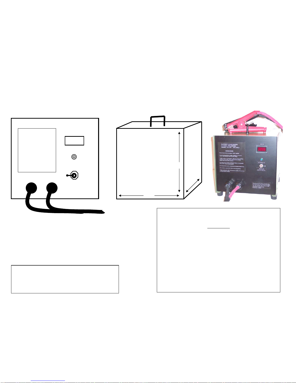
1.1 The ST-375 (P/N 37512) High Rate Discharge Unit is For testing SLI (Starting, Lighting, Ignition) engine start
batteries. It is used to accept or reject reject 12-Volt engine start batteries which have been fully charged prior to
testing. The ST-375 is designed to work on batteries that have CCA (Cold Cranking Amps) ratings in the
approximate range of 700 CCA to 1,000 CCA. However it will also accurately test batteries with a higher CCA
rating such as those used in large commercial trucks and military tactical vehicles. The unit is essentially an
SAE (Society of Automotive Engineers) tester which places a 375 Ampere load on the battery for a period of 15
seconds. A digital voltmeter on the unit reads and holds the battery voltage at the end of 15 seconds. If the
voltage is at or above 10.0 volts, the battery is ready for issue. If the voltage is below 10.0 volts the battery is
rejected. The battery may be recharged for another test depending on circumstances such as if this were a first
attempt to condition the rejected battery. The ST-375 has a high wattage resistive load bank. The resistors do
not glow during the 15 second test. The control switch has an automatic position which is pressed, released, and
tests for 15 seconds. A manual position can be pressed for less then 15 seconds. An internal 500 Ampere Shunt
has its test terminals (Kelvin Terminals) connected to a pair of test points on the front panel. The voltmeter also
has test points.
1.2 This procedure describes the verification of accuracy of Power Products High rate Discharger Tester P/N
37512. The 37512 being verified is referred to herein as the TI (Test Instrument). The TI operates from the
battery being tested and does not require any other power.
1.3 This procedure includes tests of essential performance parameters only. Any malfunction or out of limit
readings noticed during these procedures, whether specifically tested for or not, should be referred to power
products.
Table 1. Verification Description
TI Characteristics Performance Specification Test Method
Voltmeter
Internal shunt and load current
(NOTE: Shunt is 500Amp.
50 Millivolt)
2 internal timers. Timer 1
holds the voltmeter reading at
the end of 15 second test.
Timer 2 disconnects load 3
seconds after voltage hold (18
seconds total)
Range: 0 to 13 V (Meter range 99.9 V)
Tolerance: 0.2 V
Range: 0 to 38MV/380Amp
Tolerance: 1.0 Millivolts/ 10 Amps
Actual load tolerance is 375 Amps ± 10
Amps at 10.5 Volts 10 Seconds of load
(.028 Ohms at 10 Seconds)
TIME: tolerance 2 Seconds
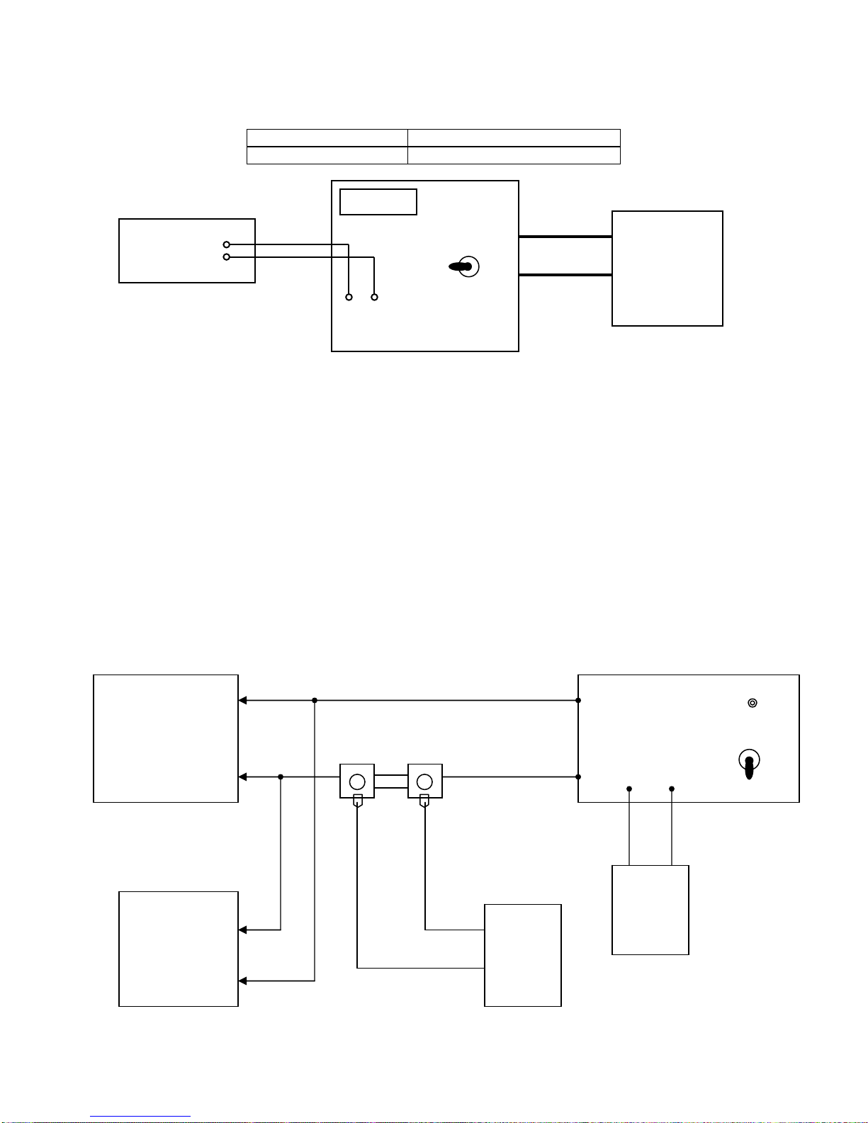
Connect to battery or power supply, keep
TI power switch OFF. Compare TI
voltmeter reading with multi-meter.
Load the TI with a battery or high current
12 volt power supply. Use external shunt
and 2 multi-meters. Compare TI reading
with one multi-meter and with external
shunt and second multi-meter.
NOTE: Amp reading is 10X millivolt
reading
Check with Quartz stop-watch or timer.
1

SECTION 2
EQUIPMENT REQUIREMENTS
NOTES
Minimum use specifications are the principal parameters required for performance of the verification, and are
included to assist in the selection of alternate equipment, which may be used at the discretion of the using facility.
Satisfactory performance of alternate items shall be verified prior to use. The applicable multimeters, and external
shunt must bear evidence of current calibration. Timer or Stop watch can be verified with a known accurate
timekeeper.
The instruments utilized in this procedure were selected from those known to be available at Naval and Marine
Corps facilities and the listing by make or model number carries no implication of preference, recommendation, or
approval for use by other agencies. It is recognized that equivalent equipment produced by other manufacturers may
be capable of equally satisfactory performance in this procedure.
Table 2. Equipment Requirements for TI
Item Minimum Use
Specifications Calibration
Equipment
SECTION 3
PRELIMINARY OPERATIONS
3.1 Ensure that power switch is set to OFF to avoid arcing or damage to the battery or power supply terminals or the
TI battery clamps.
3.2 Connect the Battery or power supply to the TI. Observe polarity.
SECTION 4
VERIFICATION PROCESS
NOTE: Unless otherwise specified, verify the results of each test and take corrective action whenever the test
requirement is not met before proceeding.
4.1 Voltmeter tests when its power switch is set to OFF.
4.1.1 TI voltmeter reads battery or power supply volts.
4.1.2 Set the DMM to read DC volts.
4.1.3 Connect the DMM as shown in Figure 1.
4.1.4 Compare the reading of the DMM to the TI voltmeter. Per Table 3
2.1 Two Digital multi-meters
(DMM)
2.2 Calibrated shunt 10 Amperes
per Millivolt
Eg. 500Amp 50mv or 1000Amp
100mv Shunt
2.3 Charged Optima battery or
power supply capable of 400Amps
12.5V - 10V for 15 Seconds
2.4 Timer
DC volts to 13V
(2)DC millivolts to 40MV
Range: 0 to 50mV
NA
NA
FLUKE 77AN
Local Supply
Local Supply
Local Supply
2

Table 3. Tolerance Limits: 0.2V
TI Voltmeter DMM Tolerance Limit
12.7 (example) 12.5 – 12.9 (±0.2)
Figure 1. Voltmeter Test Setup
HI +
DMM
LO -
TI
VOLTMETER
AUTO
RED
BLACK
OFF
+ - MANUAL
VOLTS
TEST POINTS
+
POWER SUPPLY
DC OR
CABLE CHARGED 12V
BATTERY
-
WARNING
HARMFUL CURRENTS AND VOLTAGES MAY BE PRESENT IN THE TI DC BATTERY CABLE
LEADS. THE TI ON/OFF/RESET SWITCH MUST BE SET TO THE OFF POSITION BEFORE CONNECTING
OR DISCONNECTING THE TI DC BATTERY CABLE TO/FROM THE BATTERY.
4.1.6 LOAD CURRENT TESTS
Connect the equipment as shown in Figure 2.
4.1.7 Ensure that the AUTO-OFF-MANUAL switch is set to OFF
4.1.8 Connect shunt as described in table 2 item 2.2 and power supply or optima battery as described in table 2 item
2.3
4.1.9 Set switch to Manual to obtain Readings. Load will not remain on over 15 seconds. Refer to table 5, par 4.1.16
AMMETER AND SHUNT TEST SETUP
Figure 2. Ammeter Test Setup
3
+
DMM
NO 1
400 AMP 12V +
POWER SUPPLY
-
(OR)
OPTIMA
BATTERY -
+ TI
EXTERNAL MILLIVOLT
CALIBRATED SHUNT TEST POINTS
-
- + 500A 50 MV or
1000A 100 MV
-
+
VOLTS
(LED)
AUTO
OFF
MANUAL

Figure 4. Timing Setup Test
4.1.10 TIMING TEST, Connect per Figure 3, refer to table 4 for tolerances.
4.1.11 Auto-Off-Manual Switch OFF.
4.1.12 Connect the TI to the Power Supply or Optima Battery.
4.1.13 Observe the stopwatch or timer. Simultaneously Set the stop watch or note the time and press the TI switch
to “AUTO”. The green led illuminates.
4.1.14 At the end of 15 seconds, the voltmeter holds (freezes) its voltage. Approximately 3 seconds later a
contactor click-out is heard and the green led turns-off.
Table 4. Timing Requirements
TI Time Tolerance Limit
“AUTO” test led ON
Load ON START
Voltmeter Holds Battery End Voltage 15 Sec
Within 2 Sec
Retains the voltage reading on hold, Load
contactor drops out. Green Led goes off. 3 Sec After Hold
Within 2 Sec
4
(LED)
AUTO
OFF
MANUAL
400 AMP 12V +
POWER
SUPPLY
-
(OR)
OPTIMA
BATTERY -
+

Table 5. Summary Table of Tolerance Requirements
TI TOLERANCE
4.1.15 Voltmeter 0.2 Volts
4.1.16 Load current and TI internal shunt accuracy. res ± 10 Amperes At 10.5V at 10 Seconds. onds.
f. Only: 375A
375 Ampe
Note: Loaded Battery may not be 10.5 Volts in 10 Sec
Use following steps when battery voltage differs from 10.5
Volts.
(For Re = 35 Amps/Volt)
TEP . Note Difference From 10.5V
75 375 Amp
XAMPLE
Actual voltage reading 10.9, difference is +0.4
Amps
ptable: Test reading is Amperes
***(4) If actual volts are 10.1 differences is -0.4 = le ps.
10.5V
S
1
2. Multiply Difference by 35
3. If higher than 10.5, add to 3
4. If lower than 10.5 subtract from
5. Acceptable Result must be the actual
reading ± 10 Amperes
E
STEPS
1.
2. 0.4 X 35 Amps = +14 Amps
3. 14 Amps + 375 Amps = 389
4. ***
5. Acce
389 ± 10 Amps = 379 to 399
-14Amps. Subtract from 375 Amps, Acceptab
reading is 361 Amps ± 10 Amps = 351 to 371 Am
TIME
13-17 Seconds voltage reading freezes
16-20 Seconds Drop-out of load, led off
5

HIGH DISCHARGE RATE 12V BATTERY TESTER P/N 37512
375 AMPERE 15 SECOND LOAD TEST FOR 12V
OPTIMA/HAWKER GSE BATTERIES. SAE TEST FOR ALL
12 V ENGINES START BATTERIES
SPECIFICATIONS:
POWERED BY BATTERY UNDER TEST / FAN COOLED
SAFETY LOAD – LOAD RESISTORS DO NOT GLOW
AUTOMATIC 15 SECOND OR MANUAL TEST
VOLTMETER HOLDS END OF TEST READING UNTIL RESET
WEIGHT: 15 LBS
APPLICATION: BATTERY LOAD TESTER
12 VOLT, 375 AMPERE
MODEL: ST-375 P/N: 37512
INSTRUCTIONS
Check that switch is in center, OFF position
Connect Battery - Red to Positive, Black to Negative
Meter reads Battery Open Circuit voltage.
Toggle switch to “AUTOMATIC” this is a 15 sec. load test
At end of 15 seconds, meter locks-in voltage reading
[Relay click heard after lock-in.]
If voltage is at or above 10.0 volts, Battery is acceptable
Below 10.0 volts, is unacceptable
For Manual test, press and hold switch down. Cuts-Off at 15 sec
Set switch to center OFF before removing battery
When switched to OFF, the locked-in reading will revert to existing battery voltage
Manufactured by: Power Products Inc.
27Pamaron Way Ste E, Novato, CA 94949
Tel: 415-883-6300 / Fax: 415-883-6302
Cage Code: 3C8X4
www.
po
w
e
r-
p
r
oducts
.
co
m
INSTRUCTIONS VOLTS
LOAD ON
AUTOMATIC
OFF
MANUAL
13”
10”
DATA SHEET 375-9/05
10”
Table of contents
Other Power Products Batteries Charger manuals