PR 9100 Series User manual

9113
Temperature /
mA Converter
No. 9113V106-UK
Product version: 9113-004

1503
PR electronics A/S tilbyder et bredt program af analoge og digitale
signalbehandlingsmoduler til industriel automation. Programmet
består af Isolatorer, Displays, Ex-barrierer, Temperaturtransmittere,
Universaltransmittere mfl. Vi har modulerne, du kan stole på i selv
barske miljøer med elektrisk støj, vibrationer og temperaturudsving,
og alle produkter opfylder de strengeste internationale standarder.
Vores motto »Signals the Best« er indbegrebet af denne filosofi – og
din garanti for kvalitet.
PR electronics A/S oers a wide range of analog and digital
signal conditioning devices for industrial automation. The product
range includes Isolators, Displays, I.S. Interfaces, Temperature
Transmitters, and Universal Devices. You can trust our products in
the most extreme environments with electrical noise, vibrations and
temperature fluctuations, and all products comply with the most
exacting international standards. »Signals the Best« is the epitome
of our philosophy – and your guarantee for quality.
PR electronics A/S ore une large gamme de produits pour le
traitement des signaux analogiques et numériques dans tous
les domaines industriels. La gamme de produits s’étend des
transmetteurs de température aux acheurs, des isolateurs aux
interfaces SI, jusqu’aux modules universels. Vous pouvez compter
sur nos produits même dans les conditions d’utilisation sévères,
p.ex. bruit électrique, vibrations et fluctuations de température.
Tous nos produits sont conformes aux normes internationales les
plus strictes. Notre devise »SIGNALS the BEST« c’est notre ligne
de conduite - et pour vous l’assurance de la meilleure qualité.
PR electronics A/S verfügt über ein breites Produktprogramm
an analogen und digitalen Signalverarbeitungsgeräte für die in-
dustrielle Automatisierung. Dieses Programm umfasst Displays,
Temperaturtransmitter, Ex- und galvanische Signaltrenner, und
Universalgeräte. Sie können unsere Geräte auch unter extremen
Einsatzbedingungen wie elektrisches Rauschen, Erschütterungen
und Temperaturschwingungen vertrauen, und alle Produkte von
PR electronics werden in Übereinstimmung mit den strengsten
internationalen Normen produziert. »Signals the Best« ist Ihre
Garantie für Qualität!
DK
UK
FR
DE

9113 - Product Version 9113-004 1
TEMPERATURE / mA CONVERTER
9113
CONTENTS
Warning....................................................................................................... 2
Symbol identification............................................................................ 2
Safety instructions................................................................................. 2
How to demount system 9000 ........................................................ 4
Advanced features................................................................................. 5
Application................................................................................................. 5
Technical characteristics...................................................................... 5
Applications............................................................................................... 6
PR 4501 display / programming front........................................... 7
Mounting / demounting the PR 4501/4511............................... 8
Ordering codes for 9113B................................................................... 9
Accessories ............................................................................................... 9
Electrical specifications........................................................................ 9
Configuration of sensor error check................................................ 14
Input signal outside range.............................................................. 14
Sensor error detection...................................................................... 14
Error indications................................................................................... 14
Connections .............................................................................................. 16
Block diagram........................................................................................... 17
Signal error and cable fault indications
without display front......................................................................... 18
Configuration / operating the function keys............................... 19
Routing diagram...................................................................................... 22
Routing diagram, Advanced settings (ADV.SET)........................ 24
Scrolling help texts in display line 3............................................... 25
Appendix.................................................................................................... 26
IECEx Installation Drawing.............................................................. 27
ATEX Installation Drawing............................................................... 30
FM Installation Drawing ................................................................... 33
INMETRO Installation Drawing ...................................................... 36
Safety Manual....................................................................................... 39

2 9113 - Product Version 9113-004
SYMBOL IDENTIFICATION
Triangle with an exclamation mark: Read the manual before installation
and commissioning of the device in order to avoid incidents that could lead
to personal injury or mechanical damage.
The CE mark proves the compliance of the device with the essential
requirements of the directives.
The double insulation symbol shows that the device is protected by
double or reinforced insulation.
Ex devices have been approved according to the ATEX directive for use in
connection with installations in explosive areas.
SAFETY INSTRUCTIONS
DEFINITIONS
Hazardous voltages have been defined as the ranges: 75...1500 Volt DC, and
50...1000 Volt AC.
Technicians are qualified persons educated or trained to mount, operate, and also
troubleshoot technically correct and in accordance with safety regulations.
Operators, being familiar with the contents of this manual, adjust and operate
the knobs or potentiometers during normal operation.
WARNING
The following operations should only be carried out on a discon-
nected device and under ESD-safe conditions:
General mounting, connection and disconnection of wires.
Troubleshooting the device.
Repair of the device and replacement of circuit breakers must
be done by PR electronics A/S only.
WARNING
Do not open the front plate of the device as this will cause dama-
ge to the connector for the display / programming front PR 4501.
This device contains no DIP-switches or jumpers.

9113 - Product Version 9113-004 3
RECEIPT AND UNPACKING
Unpack the device without damaging it. The packing should always follow the
device until this has been permanently mounted.
Check at the receipt of the device whether the type corresponds to the one
ordered.
ENVIRONMENT
Avoid direct sunlight, dust, high temperatures, mechanical vibrations and shock,
as well as rain and heavy moisture. If necessary, heating in excess of the stated
limits for ambient temperatures should be avoided by way of ventilation.
The device must be installed in pollution degree 2 or better.
The device is designed to be safe at least under an altitude up to 2 000 m.
MOUNTING
Only technicians who are familiar with the technical terms, warnings, and instruc-
tions in the manual and who are able to follow these should connect the device.
Should there be any doubt as to the correct handling of the device, please contact
your local distributor or, alternatively,
PR electronics A/S
www.prelectronics.com
The use of stranded wires is not permitted for mains wiring except when wires
are fitted with cable ends.
Descriptions of input / output and supply connections are shown in the block
diagram and on the side label.
The device is provided with field wiring terminals and shall be supplied from
a Power Supply having double / reinforced insulation. A power switch shall be
easily accessible and close to the device. The power switch shall be marked as
the disconnecting device for the device.
For installation on Power Rail 9400 the power is supplied by Power Control
module 9410.
Year of manufacture can be taken from the first two digits in the serial number.
CALIBRATION AND ADJUSTMENT
During calibration and adjustment, the measuring and connection of external
voltages must be carried out according to the specifications of this manual. The
technician must use tools and instruments that are safe to use.

4 9113 - Product Version 9113-004
NORMAL OPERATION
Operators are only allowed to adjust and operate device that are safely fixed in
panels, etc., thus avoiding the danger of personal injury and damage. This means
there is no electrical shock hazard, and the device is easily accessible.
CLEANING
When disconnected, the device may be cleaned with a cloth moistened with
distilled water.
LIABILITY
To the extent the instructions in this manual are not strictly observed, the
customer cannot advance a demand against PR electronics A/S that would
otherwise exist according to the concluded sales agreement.
HOW TO DEMOUNT SYSTEM 9000
Picture 1:
By lifting the bottom lock, the device
is detached from the DIN rail.

9113 - Product Version 9113-004 5
TEMPERATURE / mA CONVERTER
9113
• Input for RTD, TC and mA
• Active / passive mA output
• 1 or 2 channels
• Can be supplied separately or installed on power
rail, PR type 9400
• SIL 2-certified via Full Assessment
Advanced features
• Configurationandmonitoringbywayofdetachabledisplayfront(PR4501);
process calibration and signal simulation.
• Copyingoftheconfigurationfromonedevicetoothersofthesametypevia
the display front.
• TCinputscanuseeithertheinternalCJCoraterminalwithabuilt-inPt100
sensor (PR 5910Ex, channel 1 / PR 5913Ex, channel 2) for higher accuracy.
• Thedeviceautomaticallydetectswhetheritmustsupplyanactiveorapassive
current signal.
• Advancedmonitoringofinternalcommunicationandstoreddata.
• SIL2functionalityisoptionalandmustbeactivatedinamenupoint.
Application
• Thedevicecanbemountedinthesafeareaandinzone2/cl.1div.2and
receive signals from zone 0, 1, 2 and zone 20, 21, 22 including M1 / Class I/II/
III, Div. 1, Gr. A-G.
• Conversionandscalingoftemperature(Pt,NiandTC)andactivecurrent
signals.
• The9113hasbeendesigned,developedandcertifiedforuseinSIL2
applications according to the requirements of IEC 61508.
Technical characteristics
• 1greenand2redfrontLEDsindicateoperationstatusandmalfunction.
• 2.6kVACgalvanicisolationbetweeninput,outputandsupply.
mA
mA
mA
mA
*
*
-
+
-
+
+
+
-
+
-
+
44
43
42
41
44
43
42
41
14
13
12
11
31
32
33
34
54
53
52
51
6 9113 - Product Version 9113-004
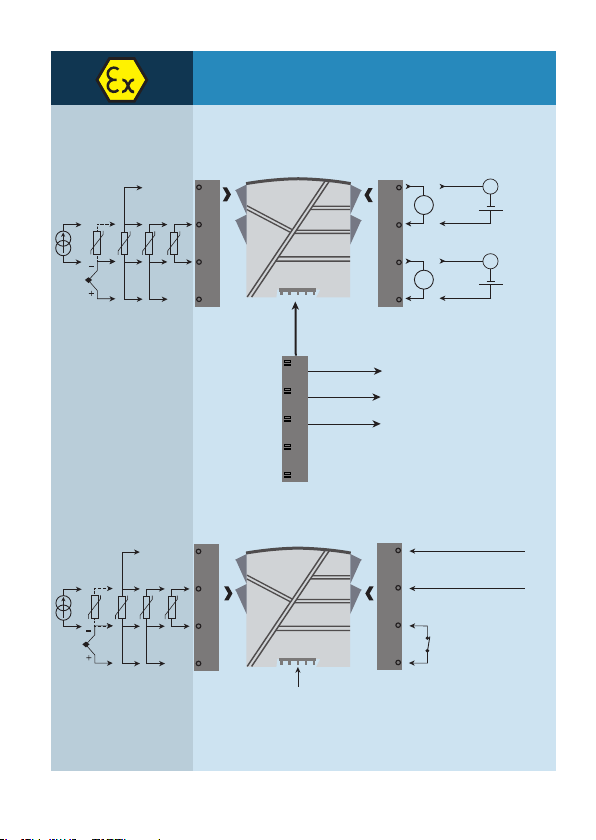
APPLICATIONS
Input signals:
Rail, +24 VDC
Rail, Gnd.
Power rail
Error signal
Analogue, 0/4...20 mA
Output signals:
Device status
Device status
Gnd.
Supply +19.2...31.2 VDC
N.C.
Power connection:
*Orderseparately:CJC
connetor 5910Ex/5913Ex
Zone 2 / Cl. 1, div. 2, gr. A-D or safe area
No connection
No connection
Channel 2:
Supply via
power rail
RTD
Connection,
wires
Current
TC
2-wire supply -
2-wire supply -
Ch. 1:
Ch. 2:
*Orderseparately:CJC
connetor 5910Ex/5913Ex
Zone 0, 1, 2,
20, 21, 22, M1 &
Cl. I/II/III, Div. 1
gr. A-G
Channel 1:
RTD
Connection,
wires
Current
TC

9113 - Product Version 9113-004 7
PR 4501 DISPLAY / PROGRAMMING FRONT
Functionality
The simple and easily understandable menu structure and the
explanatory help texts guide you effortlessly and automatically
through the configuration steps, thus making the product very
easy to use. Functions and configuration options are described
in the section ”Configuration / operating the function keys”.
Application
• Communicationsinterfaceformodificationofoperationalparametersin9113.
• Canbemovedfromone9113devicetoanotheranddownloadthe
configuration of the first unit to subsequent units.
• Whenmountedintheprocess,thedisplayshowsprocessvaluesanddevice
status.
Technical characteristics
• LCDdisplaywith4lines;Line1(H=5.57mm)showsinputstatus,line2and3
(H=3.33mm)showanalogueinput/outputvalueorTAGno.andunits,andline
4 shows status for communication and whether the device is SIL-locked. Static
dot=SIL-lockedandflashingdot=notSIL-locked.
• Programmingaccesscanbeblockedbyassigningapassword.Thepassword
is saved in the device in order to ensure a high degree of protection against
unauthorised modifications to the configuration.

OK
4501
1
3
4
2
3
8 9113 - Product Version 9113-004
MOUNTING / DEMOUNTING THE PR 4501/4511
1: Insert the taps of 4501/4511 into the holes at the top of the device.
2: Swing 4501/4511 into place.
Demounting of 4501/4511
3: Push the release button on the bottom of 4501/4511 and swing 4501/4511
up

Electrical specifications
Environmental conditions
Specifications range............................................... -20...+60°C
Storage temperature .............................................. -20...+85°C
Calibration temperature ........................................ 20...28°C
Relative humidity..................................................... < 95% RH (non-cond.)
Protection degree.................................................... IP20
Installation in............................................................. Pollution degree 2 & measurement /
overvoltage category II
Mechanical specifications:
Dimensions (HxWxD).............................................. 109 x 23.5 x 104 mm
Dimensions (HxWxD) w/ 4501 / 4511........... 109 x 23.5 x 116 / 131 mm
Weight approx........................................................... 250 g
Weight incl. 4501 / 4511 (approx.).................. 265 g / 350 g
DIN rail type............................................................... DIN EN 60715 / 35 mm
Wire size...................................................................... 0.13...2.08 mm2AWG 26...14
stranded wire
Screw terminal torque........................................... 0.5 Nm
Vibration...................................................................... IEC 60068-2-6 : 2007
Vibration: 2...13.2 Hz.............................................. ±1 mm
Vibration: 13.2...100 Hz........................................ ±0.7 g
Common specifications:
Supply voltage, DC.................................................. 19.2...31.2 VDC
Max. consumption.................................................... ≤3.5 W (2 channels)
4501 = Display / programming front
4511 = Communication enabler
5910Ex = CJC connector, channel 1
5913Ex = CJC connector, channel 2
9400 = Power rail
9404 = Module stop for rail
9410 = Power control unit
9420 = Power supply 24 V / 120 W - Ex nAC
Ordering codes for 9113B
Type Channels
9113B Single : A
Double : B
Accessories
10 9113 - Product Version 9113-004
Fuse............................................................................... 400 mA SB / 250 VAC
Isolation - test / working:
Input to any...................................................... 2.6 kVAC / 300 VAC reinforced
Analogue output to supply........................ 2.6 kVAC / 300 VAC reinforced
Status relay to supply .................................. 1.5 kVAC / 150 VAC reinforced
Communications interface ................................... Communication enabler 4511 /
Programming front 4501
Signal / noise ratio .................................................. Min. 60 dB (0...100 kHz)
Average response time incl. delay:
Temperature input......................................... ≤1 s
mA input ............................................................ ≤0.4 s
Accuracy, the greater of the general and basic values:
Basic values
Input
type Basic
accuracy Temperature
coefficient
mA ≤±16 µA ≤±1.6 µA / °C
Pt100, Pt200,
Pt 1000 ≤±0.2°C ≤±0.02°C / °C
Pt500, Ni100,
Ni120, Ni 1000 ≤±0.3°C ≤±0.03°C / °C
Pt50, Pt400, Ni50 ≤±0.4°C ≤±0.04°C / °C
Pt250, Pt300 ≤±0.6°C ≤±0.06°C / °C
Pt20 ≤±0.8°C ≤±0.08°C / °C
Pt10 ≤±1.4°C ≤±0.14°C / °C
TC type:
E,J,K,L,N,T,U
≤±1°C
≤±0.1°C / °C
TC type: R, S, W3,
W5, LR
≤±2°C
≤±0.2°C / °C
TC type: B
160...400°C ≤±4.5°C ≤±0.45°C / °C
TC type: B
400...1820°C ≤±2°C ≤±0.2°C / °C
General values
Input
type Absolute
accuracy Temperature
coefficient
All ≤±0.1% of span ≤±0.01% of span / °C

9113 - Product Version 9113-004 11
EMC immunity influence.................................................. < ±0.5% of span
Extended EMC immunity:
NAMUR NE 21, A criterion, burst ................................. < ±1% of span
RTD input:
Input for RTD types:
Pt10*, Pt20*, Pt50*, Pt100, Pt200, Pt250, Pt300, Pt400, Pt500, Pt1000
Ni50, Ni100, Ni120, Ni1000
Cable resistance per wire (max.)....................... 50 Ω
Sensor current........................................................... Nom. 0.2 mA
Effect of sensor cable resistance
(3- / 4-wire)................................................................ < 0.002 Ω/ Ω
Sensor error detection........................................... Programmable ON / OFF
Sensor error current:
when detecting............................................... < 2 μA
else......................................................... 0 μA
* No short circuit detection for Pt10, Pt20 and Pt50
TC input:
Input
type Min.
value Max.
value
Standard
Pt100
Ni100 -200°C
-60°C +850°C
+250°C IEC60751
DIN 43760
Type Min.
value Max.
value
Standard
B
E
J
K
L
N
R
S
T
U
W3
W5
LR
+0°C
-100°C
-100°C
-180°C
-200°C
-180°C
-50°C
-50°C
-200°C
-200°C
0°C
0°C
-200°C
+1820°C
+1000°C
+1200°C
+1372°C
+900°C
+1300°C
+1760°C
+1760°C
+400°C
+600°C
+2300°C
+2300°C
+800°C
IEC 60584-1
IEC 60584-1
IEC 60584-1
IEC 60584-1
DIN 43710
IEC 60584-1
IEC 60584-1
IEC 60584-1
IEC 60584-1
DIN 43710
ASTM E988-90
ASTM E988-90
GOST 3044-84

12 9113 - Product Version 9113-004
Coldjunctioncompensation(CJC):
via external sensor in connector 5910. 20...28°C ≤±1°C
-20...20°C and 28...70°C ≤±2°C
viainternalCJCsensor.................................. ±(2.0°C + 0.4°C * ∆t)
∆t=internaltemperature-ambienttemperature
Sensor error detection........................................... Programmable ON or OFF
(only wire breakage)
Sensor error current:
when detecting............................................... Nom. 2 μA
else....................................................................... 0 μA
Current input:
Measurement range................................................ 0...20 mA
Programmable measurement ranges............... 0...20 and 4...20 mA
Input resistance........................................................ Nom. 20 Ω+ PTC 50 Ω
Sensor error detection........................................... Programmable ON / OFF
Only 4...20 mA (NAMUR)
Current output:
Signal range (span)................................................. 0...20 mA
Programmable signal ranges............................... 0...20 / 4...20 /
20...0 and 20...4 mA
Load (max.)................................................................. 20 mA / 600 Ω/ 12 VDC
Load stability............................................................. ≤0.01% of span / 100 Ω
Sensor error detection........................................... 0 / 3.5 / 23 mA / none
NAMUR NE 43 Upscale/Downscale................. 23 mA / 3.5 mA
Output limitation:
on 4...20 and 20...4 mA signals................ 3.8...20.5 mA
on 0...20 and 20...0 mA signals .............. 0...20.5 mA
Current limit ............................................................... ≤28 mA
2-wire 4...20 mA output:
Signal range............................................................... 4...20 mA
Load stability............................................................. ≤0.01% of span / 100 Ω
Load resistance......................................................... ≤(Vsupply -3.5)/0.023 A [Ω]
External 2-wire supply range ............................. 3.5...26 VDC
Effect of external 2-wire supply
voltage variation...................................................... < 0.005% of span / V
Status relay in safe area:
Max. voltage .............................................................. 125 VAC / 110 VDC
Max. current............................................................... 0.5 AAC / 0.3 ADC
Max. AC power .......................................................... 62.5 VA / 32 W
of span =ofthecurrentlyselectedmeasurementrange

9113 - Product Version 9113-004 13
Approvals:
EMC 2004/108/EC .................................................. EN 61326-1
LVD 2006/95/EC...................................................... EN 61010-1
c UL us, Standard for Safety................................ UL 61010-1
EAC TR-CU 020/2011............................................ EN 61326-1
Marine:
Det Norske Veritas, Ships & Offshore ............. Stand. f. Certific. No. 2.4
I.S. / Ex:
ATEX 94/9/EC............................................................ KEMA 07ATEX0148 X
IECEx............................................................................. IECEx KEM 09.0052X
c FM us......................................................................... 3038279-C
INMETRO ..................................................................... NCC 12.1310 X
CCOE.............................................................................. P337349/3
EAC Ex TR-CU 012/2011..................................... RU C-DK.GB08.V.00410
Functional Safety:
SIL2 Certified & Fully Assessed acc. to IEC 61508
14 9113 - Product Version 9113-004
Configuration of sensor error check
Visualisation in the 4501 of:
Input signal outside range
Sensor error detection
Error indications
Sensor error check:
Device: Configuration Sensor error detection:
9113 OUT.ERR=NONE. OFF
Else: ON
Outside range readout (IN.LO, IN.HI):
If the valid range of the A/D converter or the polynomal is exceeded
Input Range Readout Limit
CURR 0...20 mA / 4...20 mA IN.LO < -1.05 mA
IN.HI > 25.05 mA
TEMP TC / RTD IN.LO < temperature range -2°C
IN.HI > temperature range +2°C
Sensor error detection (SE.BR, SE.SH):
Input Range Readout Limit
CURR Loop break (4...20 mA) SE.BR <=3.6mA;>=20.75mA
TEMP
TC SE.BR > 10 kΩ...165 kΩ
RTD: 2-, 3- and 4-wire
For Pt10, Pt20, Pt50, Pt100, Pt200, Ni50 and
Ni120
SE.BR > 900...1000 Ω
(cable > 50 Ω)
SE.SH < app. 15 Ω
RTD: 2-, 3- and 4-wire
for Pt250, Pt300, Pt400, Pt500, Pt1000 and
Ni1000
SE.BR > 10...12 kΩ
(cable > 50 Ω)
SE.SH < app. 15 Ω
Display readout below min. / above max. (-1999, 9999):
Input Range Readout Limit
All All -1999 Display readout <-1999
9999 Display readout >9999
Readout at hardware error
Error search Readout Cause
Input underrange IN.LO See conditions above
Input overrange IN.HI See conditions above
Sensor wire breakage SE.BR See conditions above
Sensor short circuit SE.SH See conditions above
TestofinternalCJCsensor CJ.ER InternalCJCsensordefectorCJC
temperature out of range**
CJCconnectorerror-checkCJC-connectorblock CJ.CE DefectormissingCJC-connector,
temperature out of allowed range

9113 - Product Version 9113-004 15
! All error indications in the display flash once per second. The help text explains the error.
* Error is acknowledged by either stepping through the basic setup, or by resetting the device power.
Some types of errors can only be acknowledged by resetting the device power.
** Error is acknowledged by either stepping through the basic setup, or by resetting the device power.
Error can be disregarded by selecting input type different than TC.
*** Error is acknowledged by stepping through the basic setup.
Readout at hardware error
Error search Readout Cause
Input error - check input connection and reset power IN.ER
Signal levels on input beyond
limits or connected to wrong
terminals*
Output error - check output connections and reset power AO.ER Error in analogue output
current (SIL mode only)*
No communication NO.CO No communication with
(4501)
Flash memory error - check configuration FL.ER
CO.ER
FLASH error (configuration
invalid)***
Invalid configuration type or version TY.ER
Configuration read from
EEprom has invalid type or
rev. no.
Hardware error RA.ER RAM error*
Hardware error IF.ER Internal Flash error*
Hardware error SW.ER SW monitor error*
Hardware error AD.ER A/D converter error*
Hardware error AO.SU Analogue output supply error*
Hardware error CA.ER Factory calibration error*
Hardware error CM.ER Main CPU error*
Hardware error II.ER Initialisation check error*
Hardware error RS.ER Reset error*
Hardware error IC.ER Input communication error*
Hardware error M1.ER Main CPU to Ch.1 error*
Hardware error M2.ER Main CPU to Ch.2 error*
Hardware error MC.ER Main CPU config. error*
Hardware error MF.ER Main CPU Flash error*
Hardware error MR.ER Main CPU RAM error*
Hardware error MS.ER Main CPU supply error*
Hardware error MP.ER Main CPU ProgFlow error*
41 42 43 44 41 42 43 44 41 42 43 44 CJC
51 52 53 54 51 52 53 54 51 52 53 54
11 12 13 14
mA mA
11 12 13 14
41 42 43 44
mA
11 12 13 14
11 12 13 14
mA
51 52 53 54
31 32 33 34
CJC
51 5452
91 92 93 94 95
-+-+
-+ -+
-+ -+
-+
+
+
-+
4441 42
16 9113 - Product Version 9113-004
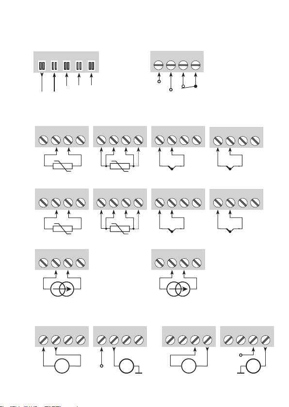
CONNECTIONS
Inputs
Outputs
Supply and
status relay
Current
(Active output
RTD, 3- / 4-wireRTD, 2-wire TC, internal
CJCsensor
Current
+24 V
N.C.
Gnd.
NCNCGnd.
+24 V
Power Rail
connections
2-wire transmitter
(Passive output)
Channel 1
RTD, 3- / 4-wireRTD, 2-wire
Channel 2Channel 1
Current
Channel 2
Channel 1
Current
(Active output 2-wire transmitter
(Passive output)
TC, internal
CJCsensor
*TC,
CJCconnector
* Order separately:
CJCconnector
5910Ex (ch. 1) /
5913Ex (ch. 2).
*TC,
CJCconnector
NC=noconnection
Error signal
9113
51
31
14
32
34
33
12
11
13
100C
12 mA
*
*
I+
mA
I+
mA
54
53
52
44
43
42
41
NC*NC*
+24V
CPU
FLASH
mA
mA
++
-
+
-
+
-
+
-
+
234
234
9113 - Product Version 9113-004 17
Status relay N.C.
Status relay N.C.
RTD, conn.
wires
Gnd.
Supply +24 VDC
Gnd.
Gnd.
Current
RTD, conn.
wires TC
Current
Gnd.
Power Rail connections
Channel 1
Channel 2
TC
Device status, Green
Ch. 1 status, Red
Ch. 2 status, Red
*NC=noconnection
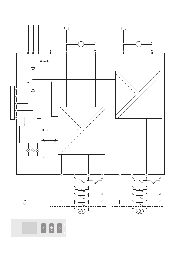
BLOCK DIAGRAM

18 9113 - Product Version 9113-004
Signal error and cable fault indications without display front
List of LED and error signal indications
Condition Green LED Ch. 1:
Red LED
Ch. 2:
Red LED
Status relay,
N.C.
Power rail
signal status
Device OK Flashing OFF OFF Energized Open
No supply OFF OFF OFF De-energized Closed
Device defective OFF ON ON De-energized Closed
Ch. 1 defective (ch. 2 OK) Flashing ON OFF De-energized Closed
Ch. 2 defective (ch. 1 OK) Flashing OFF ON De-energized Closed
Channel 1, signal OK Flashing OFF OFF Energized Open
Ch. 1, wire short / break Flashing Flashing OFF De-energized Closed (if activated)
Channel 2, signal OK Flashing OFF OFF Energized Open
Ch. 2, wire short / break Flashing OFF Flashing De-energized Closed (if activated)
This manual suits for next models
3
Table of contents
Other PR Media Converter manuals


