PR 6 MM Series User manual

SIGNALS THE BEST
(8182)63-90-72
(7172)727-132
(8512)99-46-04
(3852)73-04-60
(4722)40-23-64
(4832)59-03-52
(423)249-28-31
(844)278-03-48
(8172)26-41-59
(473)204-51-73
(343)384-55-89
(4932)77-34-06
(3412)26-03-58
(843)206-01-48
(4012)72-03-81
(4842)92-23-67
(3842)65-04-62
(8332)68-02-04
(861)203-40-90
(391)204-63-61
(4712)77-13-04
(4742)52-20-81
(3519)55-03-13
(495)268-04-70
(8152)59-64-93
(8552)20-53-41
(831)429-08-12
(3843)20-46-81
(383)227-86-73
(3812)21-46-40
(4862)44-53-42
(3532)37-68-04
(8412)22-31-16
(342)205-81-47
-- (863)308-18-15
(4912)46-61-64
(846)206-03-16
- (812)309-46-40
(845)249-38-78
(8692)22-31-93
(3652)67-13-56
(4812)29-41-54
(862)225-72-31
(8652)20-65-13
(3462)77-98-35
(4822)63-31-35
(3822)98-41-53
(4872)74-02-29
(3452)66-21-18
(8422)24-23-59
(347)229-48-12
(4212)92-98-04
(351)202-03-61
(8202)49-02-64
(4852)69-52-93
: pcn@nt-rt.ru || www.prelectronic.nt-rt.ru
3117

PR electronics A/S tilbyder et bredt program af analoge og digitale
signalbehandlingsmoduler til industriel automation. Programmet
består af Isolatorer, Displays, Ex-barrierer, Temperaturtransmittere,
Universaltransmittere m. Vi har modulerne, du kan stole på i selv
barske miljøer med elektrisk støj, vibrationer og temperaturud-
sving, og alle produkter opfylder de strengeste internationale stan-
darder. Vores motto »Signals the Best« er indbegrebet af denne
loso – og din garanti for kvalitet.
PR electronics A/S offers a wide range of analogue and digital
signal conditioning devices for industrial automation. The product
range includes Isolators, Displays, Ex Interfaces, Temperature
Transmitters, and Universal Devices. You can trust our products
in the most extreme environments with electrical noise, vibrations
and temperature uctuations, and all products comply with the
most exacting international standards. »Signals the Best« is the
epitome of our philosophy – and your guarantee for quality.
PR electronics A/S offre une large gamme de produits pour le
traitement des signaux analogiques et numériques dans tous
les domaines industriels. La gamme de produits s’étend des
transmetteurs de température aux afcheurs, des isolateurs aux
interfaces SI, jusqu’aux modules universels. Vous pouvez compter
sur nos produits même dans les conditions d’utilisation sévères,
p.ex. bruit électrique, vibrations et uctuations de température.
Tous nos produits sont conformes aux normes internationales les
plus strictes. Notre devise »SIGNALS the BEST« c’est notre ligne
de conduite - et pour vous l’assurance de la meilleure qualité.
PR electronics A/S verfügt über ein breites Produktprogramm
an analogen und digitalen Signalverarbeitungsmodule für die in-
dustrielle Automatisierung. Dieses Programm umfasst Displays,
Temperaturtransmitter, Ex- und galvanische Signaltrenner, und
Universalgeräte. Sie können unsere Geräte auch unter extremen
Einsatzbedingungen wie elektrisches Rauschen, Erschütterungen
und Temperaturschwingungen vertrauen, und alle Produkte von
PR electronics werden in Übereinstimmung mit den strengsten
internationalen Normen produziert. »Signals the Best« ist Ihre
Garantie für Qualität!
DK
UK
FR
DE
1246

3117V100-UK 1
6 MM SERIES
BIPOLAR ISOLATED CONVERTER
3117
CONTENTS
Warning .......................................................................................... 2
Safety instructions.......................................................................... 3
Mounting and demounting of system 3100................................... 5
Installation on DIN rail .................................................................... 6
Marking........................................................................................... 6
Side label........................................................................................ 7
EC declaration of conformity ......................................................... 8
Applications.................................................................................... 9
Technical characteristics................................................................ 9
Mounting / installation.................................................................... 9
Specifications................................................................................. 10
DIP-switch configuration................................................................ 12
Front LED indication (green)........................................................... 12
Connections ................................................................................... 13
2 3117V100-UK
SYMBOL IDENTIFICATION
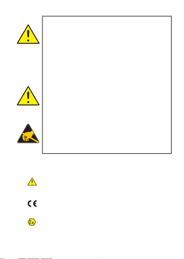
Triangle with an exclamation mark: Read the manual
before installation and commissioning of the device in
order to avoid incidents that could lead to personal injury
or mechanical damage.
The CE mark proves the compliance of the device with
the essential requirements of the directives.
Ex devices have been approved according to the ATEX
directive for use in connection with installations in
explosive areas.
WARNING
To avoid the risk of electric shock and fire, the safety instructions
of this guide must be observed and the guidelines followed.
The specifications must not be exceeded, and the device must
only be applied as described in the following. Prior to the
commissioning of the device, this installation guide must be
examined carefully. Only qualified personnel (technicians) should
install this device. If the equipment is used in a manner not
specified by the manufacturer, the protection provided by the
equipment may be impaired. Until the device is fixed, do not
connect hazardous voltages to the device.
Repair of the device must be done by PR electronics A/S only.
In applications where hazardous voltage is connected to in-/
outputs of the device, sufcient spacing or isolation from wires,
terminals and enclosure - to surroundings (incl. neighbouring
devices), must be ensured to maintain protection against electric
shock.
Potential electrostatic charging hazard. To avoid the risk of
explosion due to electrostatic charging of the enclosure, do
not handle the units unless the area is known to be safe, or
appropriate safety measures are taken to avoid electrostatic
discharge.
GENERAL
HAZARD-
OUS
VOLTAGE
CAUTION

3117V100-UK 3
SAFETY INSTRUCTIONS
RECEIPT AND UNPACKING
Unpack the device without damaging it. The packing should always follow the
device until this has been permanently mounted. Check at the receipt of the
device whether the type corresponds to the one ordered.
ENVIRONMENT
Avoid direct sunlight, dust, high temperatures, mechanical vibrations and shock,
as well as rain and heavy moisture. If necessary, heating in excess of the stated
limits for ambient temperatures should be avoided by way of ventilation.
All devices can be used for Measurement / Overvoltage Category II and Pollution
Degree 2.
The device is designed to be safe at least under an altitude up to 2 000 m.
MOUNTING
Mounting and connection of the device should comply with national legislation
for mounting of electric materials, i.e. wire cross section, protective fuse, and
location. Descriptions of input / output and supply connections are shown in this
installation guide and on the side label.
The device is provided with eld wiring terminals and shall be supplied from a
Power Supply having double / reinforced insulation. A power switch should be
easily accessible and close to the device. The power switch shall be marked as the
disconnecting unit for the device.
SYSTEM 3000 must be mounted on a DIN rail according to EN 60715.
UL installation
Use 60/75°C copper conducters only.
Wire size........................... AWG 26-12
UL le number.................. E314307
The device is an Open Type Listed Process Control Equipment. To prevent injury
resulting from accessability to live parts the equipment must be installed in an
enclosure.
The power Supply unit must comply with NEC Class 2, as described by the National
Electrical Code®(ANSI / NFPA 70).
cFMus installation in Division 2 or Zone 2
Class I, Div. 2, Group A, B, C, D T4 or I, Zone 2, AEx nA IIC T4 or Ex nA IIC T4.
In class I, Division 2 or Zone 2 installations, the subject equipment shall be
mounted within a tool-secured enclosure which is capable of accepting one or
more of Class I, Division 2 wiring methods specied in the National Electrical
Code (ANSI/NFPA 70) or in Canada in the Canadian Electrical Code (C22.1).
The 3000 System Isolators and Converters must be connected to limited output
NEC Class 2 circuits, as outlined in the National Electrical Code®(ANSI / NFPA
70), only. If the devices are connected to a redundant power supply (two separate
power supplies), both must meet this requirement.

4 3117V100-UK
Where installed in outdoor or potentially wet locations the enclosure shall at a
minimum meet the requirements of IP54.
Warning: Substitution of components may impair suitability for zone 2 / division 2.
Warning: To prevent ignition of the explosive atmospheres, disconnect power
before servicing and do not separate connectors when energised and an
explosive gas mixture is present.
Warning: Do not mount or remove devices from the power rail when an explosive
gas mixture is present.
IECEx, ATEX installation in Zone 2
IECEx KEM 10.0068 X...... Ex nA IIC T4 Gc
KEMA 10ATEX0147 X....... II 3G Ex nA IIC T4 Gc
For safe installation the following must be observed. The device shall only be
installed by qualied personnel who are familiar with the national and international
laws, directives and standards that apply to this area.
Year of manufacture can be taken from the rst two digits in the serial number.
The devices shall be installed in a suitable enclosure providing a degree
of protection of at least IP54 according to EN 60529, taking into account the
environmental conditions under which the equipment will be used.
When the temperature under rated conditions exceeds 70°C at the cable or
conduit entry point, or 80°C at the branching point of the conductors, the
temperature specication of the selected cable shall be in compliance with the
actual measured temperature.
Provisions shall be made to prevent the rated voltage from being exceeded by
transient disturbances of more than 40%.
For installation on power rail in Zone 2, only Power Rail type 9400 supplied by
Power Control Unit type 9410 is allowed.
To prevent ignition of the explosive atmospheres, disconnect power before
servicing and do not separate connectors when energised and an explosive gas
mixture is present.
Do not mount or remove devices from the power rail when an explosive gas
mixture is present.
Cleaning
When disconnected, the device may be cleaned with a cloth moistened with
distilled water.
3117V100-UK 5
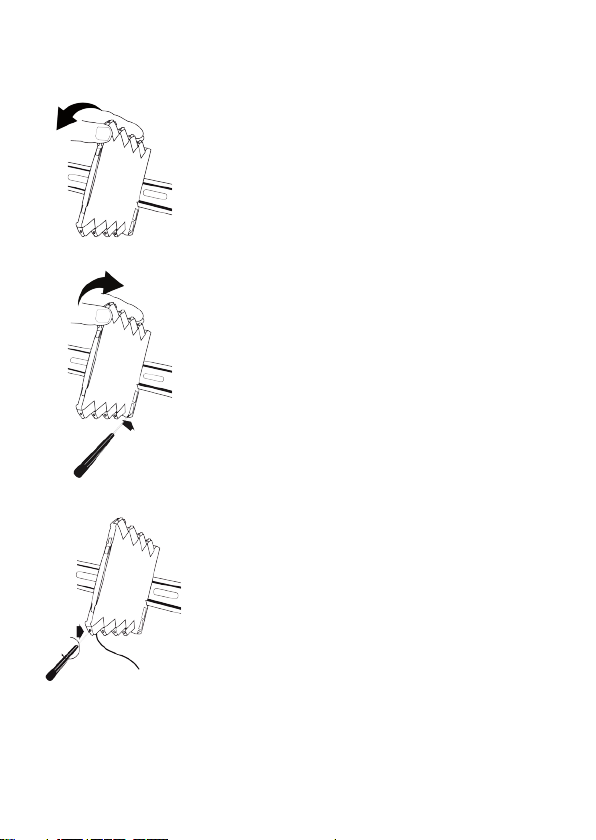
MOUNTING AND DEMOUNTING OF SYSTEM 3100
Picture 1:
Mounting on DIN rail.
Click the device onto the rail.
Picture 2:
Demounting from DIN rail
First, remember to demount the connectors with
hazardous voltages.
Detach the device from the DIN rail by lifting the
bottom lock.
Picture 3:
Wire size AWG 26-12 / 0.13 x 2.5 mm2stranded wire.
Screw terminal torque 0.5 Nm.

< 3,5 mm
> 24 mm
35 mm
6 3117V100-UK
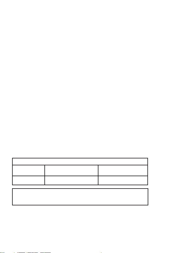
INSTALLATION ON DIN RAIL
To avoid short circuit between the power rail connectors on the 3000 devices
and the screws holding the 7.5 mm DIN rail, the head of the screws shall be
no more than 3.5 mm high.
3117 must be supported
by module stops for marine
applications.
(PR part number 9404).
MARKING
The front cover of the 3000
series has been designed
with an area for affixation
of a click-on marker. The
area assigned to the marker
measures 5 x 7.5 mm. Markers
from Weidmüller’s MultiCard
System, type MF 5/7.5, are
suitable.
Module stop
}
}
}
}
3xxx
3117V100-UK 7
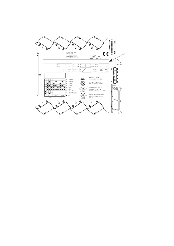
SIDE LABEL
DIP-switch
settings Approvals
Pin
connections
Type no.
Terminal numbers

8 3117V100-UK
EC DECLARATION OF CONFORMITY
As manufacturer
PR electronics A/S
hereby declares that the following product:
Type: 3117
Name: Bipolar isolated converter
is in conformity with the following directives and standards:
The EMC Directive 2004/108/EC and later amendments
EN 61326-1 : 2006
For specification of the acceptable EMC performance level, refer to the electrical
specifications for the devices.
The Low Voltage Directive 2006/95/EC and later amendments
EN 61010-1 : 2001
The ATEX Directive 94/9/EC and later amendments
EN 60079-0 : 2009 and EN 60079-15 : 2005
ATEX certificate: KEMA 10ATEX0147 X
Notified body
DEKRA Certification B.V. (0344)
Kim Rasmussen
Manufacturer’s signature

3117V100-UK 9
3117: BIPOLAR ISOLATED CONVERTER
• Conversion of voltage and current bipolar process signals to
unipolar signals
• Multiple signal ranges are selectable via DIP-switches
• Fast response time and high output load stability
• Excellent accuracy, better than 0.05 % of selected range
• Slimline 6 mm housing
Applications
• The3117isanisolatingconverterwhichcanbeusedforsignalconversionof
standard bipolar analogue process signals into a unipolar analogue signal.
• Theunit offers3-port isolation andprovides surgesuppressionand protects
control systems from transients and noise.
• The3117alsoeliminatesgroundloopsandcanbeusedformeasuringfloating
signals.
• Mountingofthe3117canbeinSafeareaorinZone2andCl.1Div2areaand
is approved for marine applications.
Technical characteristics
• Flexible24VDC(±30%)supplyviapowerrailorconnectors.
• Excellentconversionaccuracy,betterthan0.05%ofselectedrange.
• Inputsandoutputsarefloatingandgalvanicallyseparated.
• AgreenfrontLEDindicateoperationstatusforthedevice.
• Allterminalsareprotectedagainstovervoltageandpolarityerror.
• MeetingtheNAMURNE21recommendations,the3117ensurestopmeasure-
ment performance in harsh EMC environments.
• Highgalvanicisolationof2.5kVAC.
• Fastresponsetime<7ms/>100Hzbandwidth.
—10HzbandwidthdampingpossibleviaDIP-switch.
• Excellentsignal/noiseratio>60dB.
Mounting / installation
• FastandeasyconfigurationoffactorycalibratedmeasurementrangesviaDIP-
switches.
• AverylowpowerconsumptionallowsDINrailmountingwithupto165units
per metre without the need for any air gap.
• Widetemperatureoperationrange:-25...+70°C.

10 3117V100-UK
Specifications
Environmental conditions:
Specifications range.................................... -25°Cto+70°C
Storage temperature ................................... -40°Cto+85°C
Calibration temperature............................... 20...28°C
Relative humidity......................................... <95%RH(non-cond.)
Protection degree........................................ IP20
Installation in pollution degree 2 & measurement / overvoltage category II
Mechanical specifications:
Dimensions(HxWxD)................................... 113 x 6.1 x 115 mm
Weight approx. ............................................ 70 g
DIN rail type................................................. DIN EN 60715 - 35 mm
Wire size...................................................... 0.13...2.5 mm2/
AWG 26...12 stranded wire
Screw terminal torque ................................. 0.5 Nm
Common electrical specifications:
Supply voltage, DC ..................................... 16.8...31.2 VDC
Internal consumption, typ./max. ................. 0.4 W / 0.65 W
Power consumption, max. .......................... 0.8 W
Isolation voltage, test .................................. 2.5 kVAC
Working isolation voltage ............................ 300 VAC / 250 VAC (Ex)
MTBF, acc. to IEC 61709 (SN29500) .......... >241years
Signal / noise ratio ...................................... >60dB
Cut-off frequency (3 dB).............................. >100Hzor10Hz
(selectable via DIP-switch)
Response time (0...90%, 100...10%) .......... <7msor<44ms
Order codes for 3117:
Type Specifications
3117 Bipolar isolated converter
Accessories for 3117:
Type Function
3405
9400
9404
Power rail connector unit
Power rail
Module stop
3117V100-UK 11
Input specifications:
Current input:
Programmable ranges................................. ±10and±20mA
Functional range.......................................... -23...+23mA
Input voltage drop....................................... <1VDC@23mA
Voltage input:
Programmable ranges................................. ±5and±10V
Functional range.......................................... -11.5...+11.5V
Input resistance........................................... ≥ 1 MW
Output specifications:
Current output:
Programmable ranges................................. 0...20 and 4...20 mA
Functional range.......................................... 0...23 mA
Load (max.).................................................. 23 mA / 600 Ω
Load stability............................................... ≤ 0.002% of span / 100 Ω
Current limit................................................. ≤ 28 mA
Voltage output:
Programmable ranges................................. 0...5, 1...5, 0...10, 2...10 V
Functional range.......................................... 0...11.5 V
Load ........................................................... >10kW
of span = of the selected range
Accuracy values
Input
type Absolute
accuracy Temperature
coefficient
All ≤±0.05% of span ≤± 0.01% of span /°C
EMC immunity influence ............................... <±0.5%ofspan
Extended EMC immunity:
NAMUR NE 21, A criterion, burst ................. <±1%ofspan

12345678910
ON
12345678910
ON
12345678910
ON
12345678910
ON
12345678910
ON
12345678910
ON
12345678910
ON
12345678910
ON
12345678910
ON
12345678910
ON
12345678910
ON
12345678910
ON
12345678910
Filter ON
Bandwidth
10 Hz
Filter OFF
Bandwidth
> 100 Hz
Input
Current
-10...+10 mA
Input
Current
-20...+20 mA
Input
Voltage
-5...+5 V
Input
Voltage
-10...+10 V
Output
Current
0...20 mA
Output
Current
4...20 mA
Output
Voltage
0...10 V
Output
Voltage
2...10 V
Output
Voltage
0...5 V
Output
Voltage
1...5 V
12 3117V100-UK
Approvals:
EMC 2004/108/EC ...................................... EN 61326-1
LVD 2006/95/EC.......................................... EN 61010-1
UL, Standard for Safety .............................. UL 61010-1
Safe Isolation............................................... EN 61140
GOST R
Marine:
Det Norske Veritas, Ships & Offshore ......... Stand. f. Certific. No. 2.4
Germanischer Lloyd .................................... VI-7-2
Ex:
ATEX 94/9/EC.............................................. KEMA 10ATEX0147 X
IECEx........................................................... KEM 10.0068 X
c FM us ....................................................... 3041043-C
DIP-switch configuration
DIP-switch positions are only read at power up
Front LED indication (green)
LED Condition Output Action required
OFF No supply/device error De-energized Connect supply/replace device
1 flash 0.5 s ON and OFF Power-up or Restart De-energized -
Flashing13Hz/15msON Device OK Energized -
Flashing1Hz/15msON Incorrect DIP-sw setting De-energized Correct setting and repower
Flashing13Hz/0.5sON Supply or hardware error De-energized Check supply/replace device
5
6
7
81
2
3
4
81 82 83 84 85
-
+
mA
-
+
-
+
-
+
-
+
V
(±) (±)
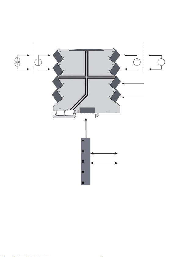
3117V100-UK 13
CONNECTIONS
Safe Area or
Zone 2 & Cl. 1, Div. 2, gr. A-D
Supply+
Supply -
Rail,+24VDC
Rail, Gnd.
No connection
No connection
Current
input
Voltage
input
Current
output
Voltage
output
Input
Supply
Output
No connection

Programmable displays with a wide
selection of inputs and outputs for display of temperature,
volume and weight, etc. Feature linearisation, scaling,
and difference measurement functions for programming
via PReset software.
Displays
A wide selection of transmitters for DIN
form B mounting and DIN rail devices with analogue
and digital bus communication ranging from application-
specic to universal transmitters.
Temperature
Galvanic isolators for analogue and digital
signalsaswellasHART®signals. A wide product range
with both loop-powered and universal isolators featuring
linearisation, inversion, and scaling of output signals.
Isolation
Interfaces for analogue and digital signals
aswellasHART®signals between sensors / I/P converters /
frequency signals and control systems in Ex zone 0, 1 & 2
and for some modules in zone 20, 21 & 22.
Ex interfaces
PC or front programmable devices with
universal options for input, output and supply. This range
offers a number of advanced features such as process
calibration, linearisation and auto-diagnosis.
Universal

:
(8182)63-90-72
(7172)727-132
(8512)99-46-04
(3852)73-04-60
(4722)40-23-64
(4832)59-03-52
(423)249-28-31
(844)278-03-48
(8172)26-41-59
(473)204-51-73
(343)384-55-89
(4932)77-34-06
(3412)26-03-58
(843)206-01-48
(4012)72-03-81
(4842)92-23-67
(3842)65-04-62
(8332)68-02-04
(861)203-40-90
(391)204-63-61
(4712)77-13-04
(4742)52-20-81
(3519)55-03-13
(495)268-04-70
(8152)59-64-93
(8552)20-53-41
(831)429-08-12
(3843)20-46-81
(383)227-86-73
(3812)21-46-40
(4862)44-53-42
(3532)37-68-04
(8412)22-31-16
(342)205-81-47
-- (863)308-18-15
(4912)46-61-64
(846)206-03-16
- (812)309-46-40
(845)249-38-78
(8692)22-31-93
(3652)67-13-56
(4812)29-41-54
(862)225-72-31
(8652)20-65-13
(3462)77-98-35
(4822)63-31-35
(3822)98-41-53
(4872)74-02-29
(3452)66-21-18
(8422)24-23-59
(347)229-48-12
(4212)92-98-04
(351)202-03-61
(8202)49-02-64
(4852)69-52-93
: pcn@nt-rt.ru || www.prelectronic.nt-rt.ru
This manual suits for next models
1
Table of contents
Other PR Media Converter manuals


Popular Media Converter manuals by other brands


Alpha Technologies
Alpha Technologies CXDF 48-24Vdc/2kW Installation & operation manual

Comnet
Comnet CWGE2SCS2 Installation and operational manual

MyGica
MyGica Capit User guide manual

ADF Web
ADF Web HD67660-A1 user manual

Bang & Olufsen
Bang & Olufsen BEOLAB 150, TYPE 1721 System manual

Audio Note
Audio Note AN-S4 Owner's Information

 user guide")


