PR 5225 User manual
Programmable displays with a wide se-
lection of inputs and outputs for display of temperature,
volume and weight, etc. Feature linearisation, scaling,
and difference measurement functions for programming
via PReset software.
Interfaces for analogue and digital
signals as well as HART®signals between sensors / I/P
converters / frequency signals and control systems in Ex
zone 0, 1 & 2 and for some modules in zone 20, 21 & 22.
Galvanic isolators for analogue and digital
signals as well as HART®signals. A wide product range
with both loop-powered and universal isolators featuring
linearisation, inversion, and scaling of output signals.
PC or front programmable modules with
universal options for input, output and supply. This range
offers a number of advanced features such as process
calibration, linearisation and auto-diagnosis.
A wide selection of transmitters for DIN
form B mounting and DIN rail modules with analogue
and digital bus communication ranging from application-
specific to universal transmitters.
Displays
Temperature
Isolation
Ex interfaces
Universal
DK
UK
FR
DE
Side 1
Page 17
Page 33
Seite 49
SIGNALS THE BEST
5225
Programmable
f/I - f/f Converter
No. 5225V101-IN (1002)
From ser. no. 970297001

1
PROGRAMMERBAR F/I - F/F KONVERTER
PRECON TYPE 5225
INDHOLDSFORTEGNELSE
Advarsel.............................................................................. 2
Sikkerhedsregler................................................................. 3
EF-overensstemmelseserklæring....................................... 5
Adskillelse af system 5000................................................. 6
Generelt.............................................................................. 7
Anvendelse......................................................................... 7
Teknisk karakteristik ........................................................... 8
Indgang .............................................................................. 8
Analog udgang ................................................................... 8
Digital(e) udgang(e)............................................................. 9
Relæudgange ..................................................................... 9
Statusindikering.................................................................. 9
Elektriske specifikationer.................................................... 10
Bestillingsskema................................................................. 14
Blokdiagram ....................................................................... 14
5225 forbindelse til Loop Link............................................ 15
2 3
SIKKERHEDSREGLER
DEFINITIONER
Farlige spændinger er defineret som områderne: 75...1500 Volt DC og
50...1000 Volt AC.
Teknikere er kvalificerede personer, som er uddannet eller oplært til at kunne
udføre installation, betjening eller evt. fejlfinding både teknisk og sikkerheds-
mæssigt forsvarligt.
Operatører er personer, som under normal drift med produktet skal indstille og
betjene produktets trykknapper eller potentiometre, og som er gjort bekendt
med indholdet af denne manual.
MODTAGELSE OG UDPAKNING
Udpak modulet uden at beskadige dette, og sørg for, at manualen altid følger
modulet og er tilgængelig. Indpakningen bør følge modulet, indtil dette er mon-
teret på blivende plads.
Kontrollér ved modtagelsen, at modultypen svarer til den bestilte.
MILJØFORHOLD
Undgå direkte sollys, kraftigt støv eller varme, mekaniske rystelser og stød, og
udsæt ikke modulet for regn eller kraftig fugt. Om nødvendigt skal opvarmning,
udover de opgivne grænser for omgivelsestemperatur, forhindres ved hjælp af
ventilation.
Alle moduler hører til Installationskategori II, Forureningsgrad 1 og Isolations-
klasse II.
INSTALLATION
Modulet må kun tilsluttes af teknikere, som er bekendte med de tekniske
udtryk, advarsler og instruktioner i manualen, og som vil følge disse.
Hvis der er tvivl om modulets rette håndtering, skal der rettes henvendelse til
den lokale forhandler eller alternativt direkte til:
PR electronics A/S, Lerbakken 10, 8410 Rønde, Danmark tlf: +45 86 37 26 77.
Installation og tilslutning af modulet skal følge landets gældende regler for
installation af elektrisk materiel bl. a. med hensyn til ledningstværsnit, for-sikring
og placering.
Beskrivelse af indgang / udgang og forsyningsforbindelser findes på blokdia-
grammet og sideskiltet.
ADVARSEL
Dette modul er beregnet for tilslutning til livsfarlige elektriske
spændinger. Hvis denne advarsel ignoreres, kan det føre til alvor-
lig legemsbeskadigelse eller mekanisk ødelæggelse. For at undgå
faren for elektriske stød og brand skal manualens sikkerhedsreg-
ler overholdes, og vejledningerne skal følges. Specifikationerne
må ikke overskrides, og modulet må kun benyttes som beskrevet
i det følgende. Manualen skal studeres omhyggeligt, før modulet
tages i brug. Kun kvalificeret personale (teknikere) må installere
dette modul. Hvis modulet ikke benyttes som beskrevet i denne
manual, så forringes modulets beskyttelsesforanstaltninger.
ADVARSEL
Der må ikke tilsluttes farlig spænding til modulet, før dette er
fastmonteret og følgende operationer bør kun udføres på
modulet i spændingsløs tilstand og under ESD-sikre forhold:
Adskillelse af modulet for indstilling af omskiftere og jumpere.
Installation, ledningsmontage og -demontage.
Fejlfinding på modulet.
Reparation af modulet og udskiftning af sikringer må kun
foretages af PR electronics A/S.
ADVARSEL
SYSTEM 5000 skal monteres på DIN-skinne efter DIN 46277.
Kommunikationsstikket i SYSTEM 5000 har forbindelse til ind-
gangsklemmer, hvor der kan forekomme farlige spændinger, og
det må kun tilsluttes programmeringsenheden Loop Link via det
medfølgende kabel.
Trekant med udråbstegn: Advarsel / krav. Hændelser der kan
føre til livstruende situationer.
CE-mærket er det synlige tegn på modulets overensstemmelse
med direktivernes væsentlige krav.
Dobbelt isolation er symbolet for, at modulet overholder ekstra
krav til isolation.
FARLIG
SPÆNDING
INSTAL-
LATION
GENERELT
SIGNATURFORKLARING

4 5
EF-OVERENSSTEMMELSESERKLÆRING
Som producent erklærer
PR electronics A/S
Lerbakken 10
DK-8410 Rønde
hermed at følgende produkt:
Type: 5225
Navn: Programmerbar f/I - f/f konverter
er i overensstemmelse med følgende direktiver og standarder:
EMC-direktivet 2004/108/EF og senere tilføjelser
EN 61326-1
For specifikation af det acceptable EMC-niveau henvises til modulets
elektriske specifikationer.
Lavspændingsdirektivet 2006/95/EF og senere tilføjelser
EN 61010-1
CE-mærket for overensstemmelse med lavspændingsdirektivet blev tilføjet i
året: 1997
Rønde, 11. januar 2010 Kim Rasmussen
Producentens underskrift
For moduler, som er permanent tilsluttet farlig spænding, gælder:
For-sikringens maksimale størrelse er 10 A og skal sammen med en
afbryder placeres let tilgængelig og tæt ved modulet. Afbryderen skal
mærkes således, at der ikke er tvivl om, at den afbryder spændingen
til modulet.
KALIBRERING OG JUSTERING
Under kalibrering og justering skal måling og tilslutning af eksterne spændinger
udføres i henhold til denne manual, og teknikeren skal benytte sikkerhedsmæs-
sigt korrekte værktøjer og instrumenter.
BETJENING UNDER NORMAL DRIFT
Operatører må kun indstille eller betjene modulerne, når disse er fast installeret
på forsvarlig måde i tavler el. lignende, så betjeningen ikke medfører fare for liv
eller materiel. Dvs., at der ikke er berøringsfare, og at modulet er placeret, så
det er let at betjene.
RENGØRING
Modulet må, i spændingsløs tilstand, rengøres med en klud let fugtet med
destilleret vand.
ANSVAR
I det omfang, instruktionerne i denne manual ikke er nøje overholdt, vil kunden
ikke kunne rette noget krav, som ellers måtte eksistere i henhold til den indgå-
ede salgsaftale, mod PR electronics A/S.

6 7
PROGRAMMERBAR F/I - F/F KONVERTER 5225
• Impulsbehandling
• Frekvensgenerator
• Samtidig f/I og f/f funktion
• Analog strøm- og spændingsudgang
• PNP- / NPN-udgang, relæer som option
• Programmerbar via PC og Loop Link
---------------------------------------------------------------------------------------
Forsyningsspænding: 24 VDC
---------------------------------------------------------------------------------------
INDGANGSOMRÅDE:
Frekvens: 0...20000 Hz
Følertyper: NAMUR, tacho,
NPN, PNP, TTL, S0
---------------------------------------------------------------------------------------
UDGANGSOMRÅDE:
Strøm- og spændingsudgang: 0...20 mA / 0...10 V
Relæudgange: 0...20 Hz
NPN- og PNP-udgang som f/f: 0...1000 Hz
NPN- og PNP-udgang som generator: 0...20000 Hz
---------------------------------------------------------------------------------------
GENERELT
PRecon 5225 f/I - f/f konverteren konfigureres til den ønskede funktion ved hjælp
af en standard PC og Loop Link programmeringskit.
5225 kan også leveres færdigkonfigureret efter specifikationer, se optionsindeks
i databladet.
Typiske impulsgivere kan være flowmålere, tachogeneratorer, mekaniske kontak-
ter eller induktive aftastere.
ANVENDELSE
f/I-funktionen anvendes som frekvens til strøm- og spændingskonvertering.
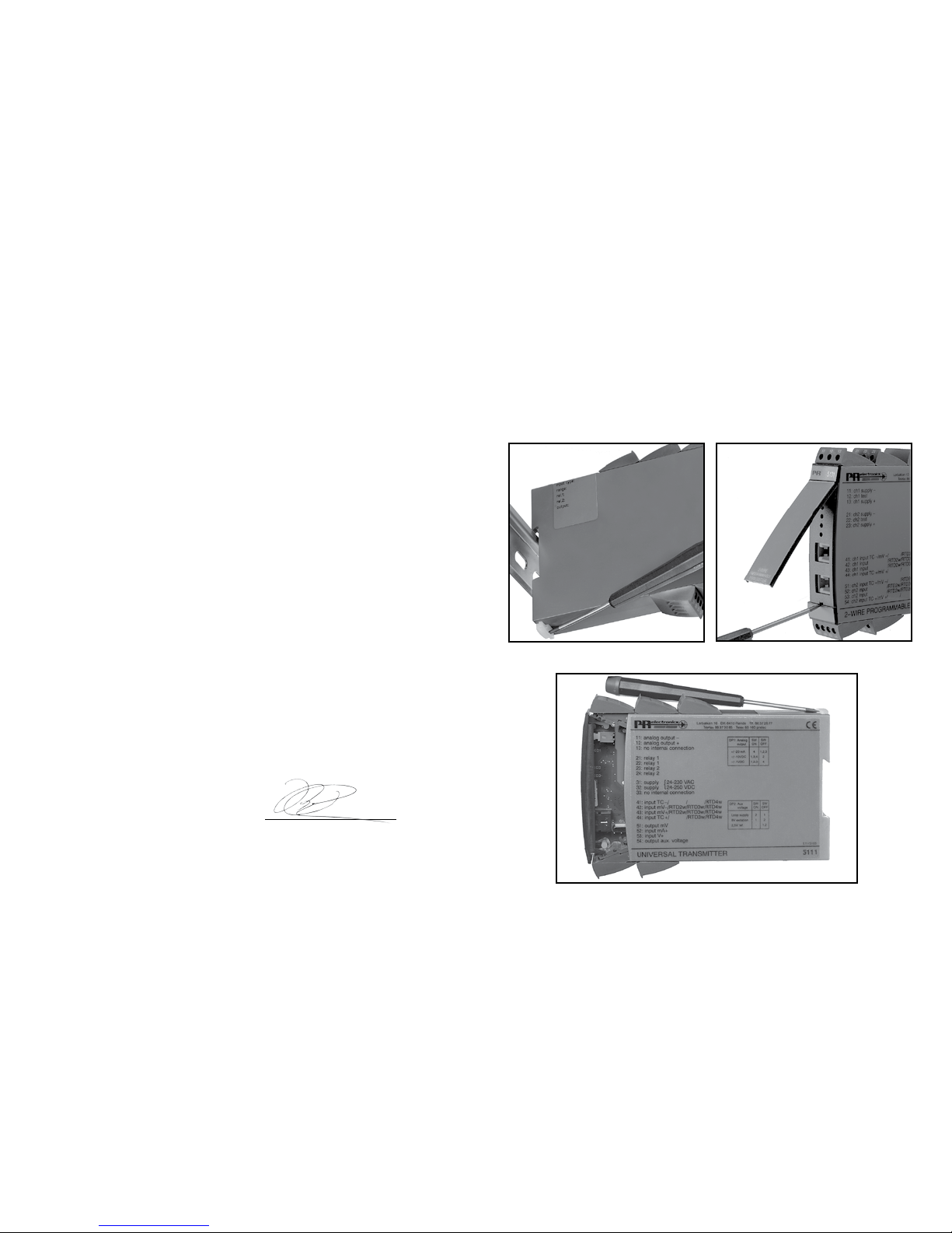
ADSKILLELSE AF SYSTEM 5000
Husk først at demontere tilslutningsklemmerne med farlig spænding.
Modulet frigøres fra DIN-skinnen ved at løfte i den nederste lås, som vist på
billede 1.
Printet udtages derefter ved at løfte i den øverste lås og samtidig trække ud i
frontpladen, se billede 2.
Nu kan switche og jumpere ændres.
Programmeringsstikket er tilgængeligt ved at åbne fronten som vist på billede 3.
Billede 1: Frigørelse fra DIN-skinne.
Billede 2: Udtagelse af print.
Billede 3: Adgang til programmeringsstik.

8 9
DIGITAL(E) UDGANG(E)
Både NPN- / PNP- og relæudgange kan opsættes med forsinket ind- og udkob-
ling.
Aktionen på udgangene kan inverteres og hysteresen kan vælges frit.
Ved spændingstilslutning kan skift på udgangene forsinkes i op til 999 s.
NPN- og PNP-udgange for eksternt relæ, elektromekanisk tæller, PLC-indgang
eller tilsvarende belastning.
Udgangene er strømbegrænsede ved hjælp af PTC-modstande.
Aktiv udgang etableres ved at forbinde NPN- til PNP-udgangen (lus ben 22
- 23).
RELÆUDGANGE
5225 kan leveres med 2 relæudgange, som programmeres individuelt.
STATUSINDIKERING
5225 har 4 lysdioder i fronten.
f in: Indikerer aktiv indgang (inaktiv ved NPN-indgang).
Dig. out 1: Indikerer aktiv NPN eller relæ 1 udgang.
Dig. out 2: Indikerer aktiv relæ 2 udgang.
Error: Indikerer følerfejl ved NAMUR-indgang.
Udgangen kan opsættes til at vise periodetid, hvilket betyder, at indgangsfre-
kvensen kan omsættes til et periodetids lineært signal.
De digitale udgange anvendes f.eks. som frekvensvagt til hastighedsovervågning
eller som vinduesfunktion med én status indenfor 2 grænser og modsat status
udenfor grænserne.
f/f-funktionen kan benyttes til neddeling eller multiplikation af impulser samt
som buffer til opsamling af hurtige pulstog.
Indgangspulserne beregnes, tælles op i en buffer og sendes derefter til udgangen
i et pulstog med den programmerede impulsbredde.
Samtidig f/I og f/f funktion gør det muligt, sammen med den analoge udgang,
at have et skaleret digitalt udgangssignal.
Frekvensgeneratorfunktionen anvendes f.eks. som time-base eller clock-
generator.
TEKNISK KARAKTERISTIK
INDGANG
Programmerbar indgang for tilslutning af standard impulsgivere.
Hjælpeforsyningen og triggerniveauet følger normalt følertypen, men kan pro-
grammeres til andre værdier.
Ved kontaktindgang bør filter for 50 Hz anvendes.
Enheden er beskyttet mod forkert polaritet på indgang og forsyning.
ANALOG UDGANG
Den analoge strøm- og spændingsudgang kan frit skaleres som udtryk for den
digitale indgang.
Nulpunktsforskydningen er på op til 50% af det valgte måleområde.
Reaktionstiden er programmerbar.
Udgangen er kortslutningssikret.
Anvendes strøm- og spændingssignalet samtidigt, skal mA-sløjfen til gnd. gen-
nem den interne shunt.
Standard spændingsudgang (ben 12) opnås ved at lede strømsignalet (ben 13)
gennem en intern shuntmodstand (ben 12).
For spændingssignaler i området 0...1 VDC anvendes 50 Ωshunt (JP1), i området
0...10 VDC anvendes 500 Ωshunt (JP2).

10 11
Indgang:
Generelt:
Måleområde ............................................... 0...20 kHz
Min. måleområde ....................................... 0,001 Hz
Max. nulpunktsforskydning (offset)............ 90% af valgt max. frekvens
Low cut off ................................................. 0,001 Hz
Min. impulsbredde (uden filter) .................. 25 µs
Min. periodetid (uden filter) ........................ 50 µs
Max. frekvens (uden filter).......................... 20 kHz
Min. impulsbredde (med filter) ................... 10 ms
Min. periodetid (med filter) ......................... 20 ms
Max. frekvens (med filter)........................... 50 Hz
Programmerbare trig-niveauer ................... 0,025...6,5 V (nom.)
Trig-niveau LOW......................................... > 50% af trig high
- 50 mV
NAMUR-indgang efter DIN 19234:
Trig-niveau LOW......................................... ≤ 1,2 mA
Trig-niveau HIGH........................................ ≥ 2,1 mA
Indgangsimpedans..................................... 1000 Ω
Følerfejlsdetektion (kun for NAMUR):
Brud............................................................ ≤ 0,1 mA
Kortslutning ................................................ ≥ 7,0 mA
Reaktionstid ............................................... ≤ 400 ms
Tacho-indgang:
Trig-niveau LOW......................................... ≤ - 50 mV
Trig-niveau HIGH........................................ ≥ 50 mV
Indgangsimpedans..................................... ≥100 kΩ
Max. indgangsspænding............................ 80 VAC pp
NPN- / PNP-indgang:
Trig-niveau LOW......................................... ≤ 4,0 V
Trig-niveau HIGH........................................ ≥ 7,0 V
Indgangsimpedans, standard..................... 3,48 kΩ
Indgangsimpedans, specialudgave............ 13,3 kΩ / NPN
ELEKTRISKE SPECIFIKATIONER
Specifikationsområde:
-20°C til +60°C
Fælles specifikationer:
Forsyningsspænding.................................. 19,2...28,8 VDC
Egetforbrug................................................. 1,7 W
Max. forbrug............................................... 3,5 W
Power-up forsinkelse (dig. udgange) ......... 0...999 s
Opvarmningstid.......................................... 30 s
Kommunikationsinterface........................... Loop Link
Signal- / støjforhold.................................... Min. 60 dB
Reaktionstid, analog................................... < 60 ms + periodetid
Reaktionstid, digital udgang ...................... < 50 ms + periodetid
Reaktionstid, samtidig f/I og f/f.................. < 80 ms + periodetid
Kalibreringstemperatur............................... 20...28°C
Temperaturkoefficient................................. < ±0,01% af span / °C
Linearitetsfejl .............................................. < ±0,1% af span
Virkning af forsyningsspændings-
ændring ...................................................... < 0,002% af span / %V
Hjælpespændinger:
NAMUR-forsyning ...................................... 8,3 VDC ±0,5 VDC / 8 mA
S0-forsyning............................................... 17 VDC / 20 mA
NPN- / PNP-forsyning................................ 17 VDC / 20 mA
Special forsying (programmerbar).............. 5...17 VDC / 20 mA
EMC-immunitetspåvirkning........................ < ±0,5%
Max. ledningskvadrat................................. 1 x 2,5 mm2flerkoret ledning
Klemskruetilspændingsmoment................. 0,5 Nm
Luftfugtighed .............................................. < 95% RH (ikke kond.)
Mål (HxBxD) .............................................. 109 x 23,5 x 130 mm
DIN-skinne type.......................................... DIN 46277
Kapslingsklasse.......................................... IP 20
Vægt........................................................... 190 g

12 13
Frekvensgenerator:
Min. periodetid ........................................... 50 µs
Max. frekvens............................................. 20 kHz
Duty cycle................................................... 50%
Relæudgang:
Isolation, test / drift .................................... 3,75 kVAC / 250 VAC
Frekvens max. ........................................... 20 Hz
Vmax. ......................................................... 250 VRMS
Imax. .......................................................... 2 A / AC
Max. AC effekt............................................ 500 VA
Max. belastning ved 24 VDC ..................... 1 A
GOST R godkendelse:
VNIIM, Cert. no........................................... Se www.prelectronics.dk
Overholdte myndighedskrav: Standard:
EMC 2004/108/EF...................................... EN 61326-1
LVD 2006/95/EF ......................................... EN 61010-1
PELV/SELV.................................................. IEC 364-4-41 og EN 60742
Af span = Af det aktuelt valgte område
TTL-indgang:
Trig-niveau LOW......................................... ≤ 0,8 VDC
Trig-niveau HIGH............................................. ≥ 2,0 VDC
Indgangsimpedans..................................... ≥ 100 kΩ
S0-indgang efter DIN 43 864:
Trig-niveau LOW......................................... ≤2,2 mA
Trig-niveau HIGH ....................................... ≥ 9,0 mA
Indgangsimpedans..................................... 800 Ω
Analog udgang:
Strømudgang:
Signalområde ............................................. 0...20 mA
Min. signalområde...................................... 5 mA
Max. nulpunktsforskydning........................ 50% af valgt max. værdi
Signaldynamik............................................ 16 bit
Opdateringstid............................................ 20 ms
Opdateringstid for samtidig f/I og f/f ......... 40 ms
Belastning (max.)........................................ 20 mA / 600 Ω / 12 VDC
Belastningsstabilitet ................................... < ±0,01% af span / 100 Ω
Strømbegrænsning..................................... ≤ 23 mA
Spændingsudgang via intern shunt:
Signalområde ............................................. 0...10 VDC
Min. signalspan .......................................... 250 mV
Max. nulpunktsforskydning........................ 50% af valgt max. værdi
Belastning (min.)......................................... 500 kΩ
Digitale udgange (NPN / PNP):
Imax. source............................................... 30 mA
Imax. sink ................................................... 130 mA
Vmax. ......................................................... 28,5 VDC
f/f-konverter udgang:
Signalområde ............................................. 0...1000 Hz
Multiplikator / Divisor ................................. 1,0000...1000000
Min. impulsbredde...................................... 500 µs
Max. impulsbredde..................................... 999 ms
Max. duty cycle.......................................... 50%
14 15
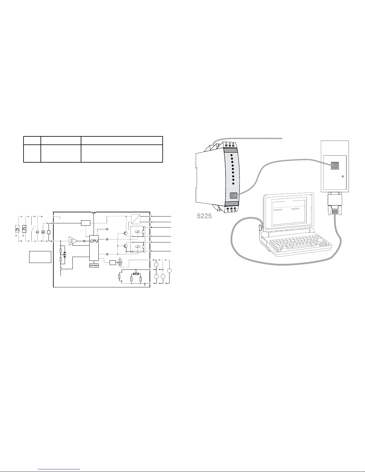
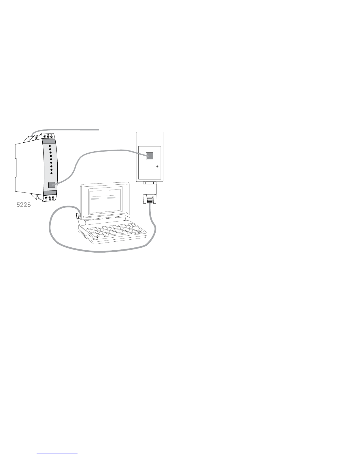
5225 FORBINDELSE TIL LOOP LINK
5225
FileProductInput
OutputCommunicationLanguageOption08:30:00
PRetop5331
Date:1994-8-10
943201594
PRelectronics
AnaloginputAnalogoutput
Serialno:
Inputtype:Output
type:4-20mA
Upscale
Sensor
error:
Pt100
DIN/IEC
0.00-50.00
C
3-wire
1.00sec
------
Inputrange:
Connection:
Coldjunction
comp:
Responsetime:
Tagno:
COM
Loop Link
Komm.
Forsyning
Komm.
BESTILLINGSSKEMA
BLOKDIAGRAM
32
31
11
V
13 I +
A
V
A
5225 50050
12 V +
JP 2
JP 1
43
41
22
21
24
23
42 f in
S0
NPN
Vreg.
JP 4
JP 3
13k3
3k48
D/A
Option
Forsynings gnd.
Gnd.
I + V
udg.
I
udg.
V
udg.
0 ... 20
mA
Indgang +
+ 24 VDC
Indgang gnd.
5 … 17 VDC
Error
Relæ 1 / NPN
Relæ 1 / dig. gnd.
Kommunikation
5 … 17V+
NamurTacho
Dig. out. 2
Dig. out. 1
Relæ 2
Relæ 2 / PNP
Forsyning +24 VDC
Spec.
V udg.
NPN pull up:
6,7 mA: JP4 ON
1,7 mA: JP3 ON
Forsyn.
+
Forsyn.
+
NPNPNP Kontakt
Type Version Udgang
5225 Standard : A Analog + NPN / PNP
Analog + relæudgang
: 1
: 2

16 17
PROGRAMMABLE F/I - F/F CONVERTER
PRECON TYPE 5225
TABLE OF CONTENTS
Warning .............................................................................. 18
Safety instructions.............................................................. 20
EC declaration of conformity ............................................. 22
How to dismantle system 5000 ......................................... 23
In general............................................................................ 24
Applications........................................................................ 25
Technical characteristics.................................................... 25
Input ................................................................................... 25
Analogue output................................................................. 25
Digital output(s) .................................................................. 26
Relay outputs ..................................................................... 26
Status indication................................................................. 26
Electrical specifications...................................................... 27
Order .................................................................................. 31
Block diagram .................................................................... 31
5225 connection to Loop Link ........................................... 32
18 19
SYMBOL IDENTIFICATION
Triangle with an exclamation mark: Warning / demand. Potentially
lethal situations.
The CE mark proves the compliance of the module with the essential
requirements of the directives.
The double insulation symbol shows that the module is protected by
double or reinforced insulation.
WARNING
This module is designed for connection to hazardous electric
voltages.
Ignoring this warning can result in severe personal injury or
mechanical damage.
To avoid the risk of electric shock and fire, the safety instructions
of this manual must be observed and the guidelines followed.
The specifications must not be exceeded, and the module must
only be applied as described in the following.
Prior to the commissioning of the module, this manual must be
examined carefully.
Only qualified personnel (technicians) should install this module.
If the equipment is used in a manner not specified by the manufac-
turer, the protection provided by the equipment may be impaired.
WARNING
SYSTEM 5000 must be mounted on DIN rail according to DIN
46277. The communication connector of SYSTEM 5000 is
connected to the input terminals on which dangerous voltages
can occur, and it must only be connected to the programming
unit Loop Link by way of the enclosed cable.
WARNING
Until the module is fixed, do not connect hazardous voltages to
the module.
The following operations should only be carried out on a
disconnected module and under ESD safe conditions:
Dismantlement of the module for setting of dipswitches
and jumpers.
General mounting, connection and disconnection of wires.
Troubleshooting the module.
Repair of the module and replacement of circuit breakers
must be done by PR electronics A/S only.
GENERAL
HAZARD-
OUS
VOLTAGE
INSTAL-
LATION

20 21
The following apply to fixed hazardous voltages-connected modules:
The max. size of the protective fuse is 10 A and, together with a power
switch, it should be easily accessible and close to the module. The
power switch should be marked with a label telling it will switch off the
voltage to the module.
CALIBRATION AND ADJUSTMENT
During calibration and adjustment, the measuring and connection of external
voltages must be carried out according to the specifications of this manual. The
technician must use tools and instruments that are safe to use.
NORMAL OPERATION
Operators are only allowed to adjust and operate modules that are safely fixed in
panels, etc., thus avoiding the danger of personal injury and damage. This means
there is no electrical shock hazard, and the module is easily accessible.
CLEANING
When disconnected, the module may be cleaned with a cloth moistened with
distilled water.
LIABILITY
To the extent the instructions in this manual are not strictly observed, the customer
cannot advance a demand against PR electronics A/S that would otherwise exist
according to the concluded sales agreement.
SAFETY INSTRUCTIONS
DEFINITIONS
Hazardous voltages have been defined as the ranges: 75 to 1500 Volt DC, and
50 to 1000 Volt AC.
Technicians are qualified persons educated or trained to mount, operate, and
also troubleshoot technically correct and in accordance with safety regulations.
Operators, being familiar with the contents of this manual, adjust and operate the
knobs or potentiometers during normal operation.
RECEIPT AND UNPACKING
Unpack the module without damaging it and make sure that the manual always
follows the module and is always available. The packing should always follow the
module until this has been permanently mounted.
Check at the receipt of the module whether the type corresponds to the one
ordered.
ENVIRONMENT
Avoid direct sunlight, dust, high temperatures, mechanical vibrations and shock,
as well as rain and heavy moisture. If necessary, heating in excess of the stated
limits for ambient temperatures should be avoided by way of ventilation.
All modules fall under Installation Category II, Pollution Degree 1, and Insulation
Class II.
MOUNTING
Only technicians who are familiar with the technical terms, warnings, and
instructions in the manual and who are able to follow these should connect the
module.
Should there be any doubt as to the correct handling of the module, please
contact your local distributor or, alternatively,
PR electronics A/S, Lerbakken 10, DK-8410 Rønde, Denmark,
tel: +45 86 37 26 77.
Mounting and connection of the module should comply with national legislation
for mounting of electric materials, i.a. wire cross section, protective fuse, and
location. Descriptions of input / output and supply connections are shown in the
block diagram and side label.
22 23
HOW TO DISMANTLE SYSTEM 5000
First, remember to demount the connectors with hazardous voltages. By lifting
the bottom lock, the module is detached from the DIN rail as shown in picture 1.
Then, by lifting the upper lock and pulling the front plate simultaneously the PCB
is removed as shown in picture 2.
Switches and jumpers can now be adjusted. By opening the front, the
programming connector is accessible as shown in picture 3.
Picture 1: Separation from DIN rail.
Picture 2: Removal of PCB.
Picture 3: Access to programming
connector.
EC DECLARATION OF CONFORMITY
As manufacturer
PR electronics A/S
Lerbakken 10
DK-8410 Rønde
hereby declares that the following product:
Type: 5225
Name: Programmable f/I - f/f converter
is in conformity with the following directives and standards:
The EMC Directive 2004/108/EC and later amendments
EN 61326-1
For specification of the acceptable EMC performance level, refer to the
electrical specifications for the module.
The Low Voltage Directive 2006/95/EC and later amendments
EN 61010-1
The CE mark for compliance with the Low Voltage directive was affixed in the
year: 1997
Rønde, 11 January 2010 Kim Rasmussen
Manufacturer’s signature

24 25
APPLICATIONS
The f/I function performs frequency to current and voltage conversion.
The output can be programmed to show period meaning that the input frequency
can be converted to a linear time signal.
The digital outputs are used as e.g. a frequency watch for speed control or as a
window comparator having one status between 2 limits and the opposite status
outside these limits.
The f/f function can be used for pulse division or multiplication and as a buffer
collecting fast pulse trains. The input pulses are calculated, counted in a buffer,
and sent to the output as a pulse train with the programmed pulse width.
The concurrent f/I and f/f functions enable a scaled digital output signal in
conjunction with the analogue output.
The frequency generator function is used as e.g. a time base or clock
generator.
TECHNICAL CHARACTERISTICS
INPUT
Programmable input for standard pulse generator connection.
Normally, the auxiliary supply and trigger level follow the sensor type, but these
can be programmed acc. to other values.
At contact input, the 50 Hz filter should be applied.
The PRecon 5225 is protected against polarity reversal on input and supply.
ANALOGUE OUTPUT
The analogue current and voltage output can be scaled acc. to your choice in
relation to the digital input. Max. zero offset is 50% of selected measurement
range. Programmable response time.
Short circuit-protected output.
When both current and voltage signals are used simultaneously, the mA loop to
ground passes through the internal shunt.
Standard voltage output (pin 12) is obtained by leading the current signal (pin
13) through an internal shunt resistor (pin 12). At current signals in the ranges
0...1 VDC, a 50 Ωshunt (JP1) is applied; in the ranges 0...10 VDC, a 500 Ωshunt
(JP2) is applied.
PROGRAMMABLE F/I - F/F CONVERTER
5225
• Pulse conditioning
• Frequency generator
• Concurrent f/I and f/f function
• Analogue current and voltage output
• PNP / NPN output, optional relays
• Programmable by PC and Loop Link
---------------------------------------------------------------------------------------
Supply voltage: 24 VDC
---------------------------------------------------------------------------------------
INPUT RANGE:
Frequency: 0...20000 Hz
Sensor types: NAMUR, tacho,
NPN, PNP, TTL, S0
---------------------------------------------------------------------------------------
OUTPUT RANGE:
Current and voltage output: 0...20 mA / 0...10 V
Relay outputs: 0...20 Hz
NPN and PNP output as f/f: 0...1000 Hz
NPN and PNP output as generator: 0...20000 Hz
---------------------------------------------------------------------------------------
IN GENERAL
By way of a standard PC and the Loop Link programming kit, the PRecon 5225
f/I - f/f Converter is configured acc. to the requested function.
Alternatively, the 5225 may be delivered fully-configured acc. to your
specifications, see the options index in the data sheet.
Typical pulse sources are flow meters, tacho generators, mechanical switches,
or inductive proximity sensors.

26 27
ELECTRICAL SPECIFICATIONS
Specifications range:
-20°C to +60°C
Common specifications:
Supply voltage............................................ 19.2...28.8 VDC
Internal consumption ................................. 1.7 W
Max. consumption...................................... 3.5 W
Power-up delay (digital outputs) ................ 0...999 s
Warm-up time............................................. 30 s
Communications interface ......................... Loop Link
Signal / noise ratio ..................................... Min. 60 dB
Response time, analogue........................... < 60 ms + period
Response time, digital output .................... < 50 ms + period
Response time, concurrent f/I and f/f........ < 80 ms + period
Calibration temperature.............................. 20...28°C
Temperature coefficient.............................. < ±0.01% of span / °C
Linearity error ............................................. < ±0.1% of span
Effect of supply voltage change................. < 0.002% of span / %V
Auxiliary voltages:
NAMUR supply........................................... 8.3 VDC ±0.5 VDC / 8 mA
S0 supply ................................................... 17 VDC / 20 mA
NPN / PNP supply...................................... 17 VDC / 20 mA
Special supply (programmable).................. 5...17 VDC / 20 mA
EMC immunity influence ............................ < ±0.5%
Max. wire size............................................. 1 x 2.5 mm2stranded wire
Screw terminal torque ................................ 0.5 Nm
Air humidity ................................................ < 95% RH (non-cond.)
Dimensions (HxWxD) ................................. 109 x 23.5 x 130 mm
DIN rail type................................................ DIN 46277
Protection degree....................................... IP20
Weight ........................................................ 190 g
DIGITAL OUTPUT(S)
Both NPN / PNP and relay outputs can be set up with delayed on and off. The
action on the outputs can be inverted, and the hysteresis can be set acc. to your
specifications.
At power-up, shifts on the outputs can be delayed for up to 999 s.
NPN and PNP outputs for external relay, electromechanical counter, PLC input,
or equivalent load.
The outputs are current-limited by way of PTC resistors.
Active output is established by connecting the NPN to the PNP output (jumper
pins 22-23).
RELAY OUTPUTS
The PRecon 5225 can be delivered with 2 relay outputs that are programmed
individually.
STATUS INDICATION
The 5225 is equipped with 4 front LEDs.
f in: Indicates an active input (non-active at NPN input).
Dig. out. 1: Indicates active NPN or relay 1 output.
Dig. out. 2: Indicates active relay 2 output.
Error: Indicates sensor error at NAMUR input.

28 29
TTL input:
Trig-level LOW............................................ ≤ 0.8 VDC
Trig-level HIGH ................................................ ≥ 2.0 VDC
Input impedance ........................................ ≥ 100 kΩ
S0 input acc. to DIN 43 864:
Trig-level LOW............................................ ≤2.2 mA
Trig-level HIGH .......................................... ≥ 9.0 mA
Input impedance ........................................ 800 Ω
Analogue output:
Current output:
Signal range ............................................... 0...20 mA
Min. signal range........................................ 5 mA
Max. offset.................................................. 50% of selected max. value
Signal dynamics ......................................... 16 bit
Updating time............................................. 20 ms
Updating time for
concurrent f/I and f/f .................................. 40 ms
Load (max.)................................................. 20 mA / 600 Ω / 12 VDC
Load stability.............................................. < ±0.01% of span / 100 Ω
Current limit................................................ ≤ 23 mA
Voltage output through internal shunt:
Signal range ............................................... 0...10 VDC
Min. signal span ......................................... 250 mV
Max. offset.................................................. 50% of selected max. value
Load (min.).................................................. 500 kΩ
Digital outputs (NPN / PNP):
Imax. source............................................... 30 mA
Imax. sink ................................................... 130 mA
Vmax. ........................................................ 28.5 VDC
f/f converter output:
Signal range ............................................... 0...1000 Hz
Multiplicator / Divisor ................................. 1.0000...1000000
Min. pulse width......................................... 500 µs
Max. pulse width........................................ 999 ms
Max. duty cycle.......................................... 50%
Input:
General:
Measurement range ................................... 0...20 kHz
Min. measurement range ........................... 0.001 Hz
Max. offset.................................................. 90% of selected max. frequency
Low cut off ................................................. 0.001 Hz
Min. pulse width (without filter) .................. 25 µs
Min. period (without filter) .......................... 50 µs
Max. frequency (without filter).................... 20 kHz
Min. pulse width (with filter) ....................... 10 ms
Min. period (with filter)................................ 20 ms
Max. frequency (with filter)......................... 50 Hz
Programmable trig-level............................. 0.025...6.5 V (nom.)
Trig-level LOW............................................ > 50% of trig high
- 50 mV
NAMUR input acc. to DIN 19234:
Trig-level LOW............................................ ≤ 1.2 mA
Trig-level HIGH ........................................... ≥ 2.1 mA
Input impedance ........................................ 1000 Ω
Sensor error detection (only for NAMUR):
Breakage .................................................... ≤ 0.1 mA
Short circuit................................................ ≥ 7.0 mA
Response time ........................................... ≤ 400 ms
Tacho input:
Trig-level LOW............................................ ≤ - 50 mV
Trig-level HIGH ........................................... ≥ 50 mV
Input impedance ........................................ ≥100 kΩ
Max. input voltage...................................... 80 VAC pp
NPN / PNP input:
Trig-level LOW............................................ ≤ 4.0 V
Trig-level HIGH ........................................... ≥ 7.0 V
Input impedance, standard........................ 3.48 kΩ
Input impedance, special version .............. 13.3 kΩ / NPN

30 31
ORDER
32
31
11
V
13 I +
A
V
A
5225 50050
12 V +
JP 2JP 1
43
41
22
21
24
23
42 f in
S0
NPN
Vreg.
JP 4
JP 3
13k3
3k48
D/A
Option
Supply gnd.
Gnd.
I + V
Out
I
Out
V
Out
0…20
mA
Input +
+ 24 VDC
Input gnd.
5…17 VDC
Error
Relay 1 / NPN
Relay 1 / dig. gnd.
Front comm.
5…17V+
NamurTacho
Dig out 2
Dig out 1
Relay 2
Relay 2 / PNP
Supply +24 VDC
Spec.
V Out
NPN pull up:
6.7 mA: JP4 ON
1.7 mA: JP3 ON
Sup.
+
Sup.
+
NPNPNP Contact
BLOCK DIAGRAM
Frequency generator:
Min. period ................................................ 50 µs
Max. frequency........................................... 20 kHz
Duty cycle................................................... 50%
Relay output:
Isolation, test / operation ........................... 3.75 kVAC / 250 VAC
Frequency max........................................... 20 Hz
Vmax. ......................................................... 250 VRMS
Imax............................................................ 2 A / AC
Max. AC power ......................................... 500 VA
Max. load at 24 VDC.................................. 1 A
GOST R approval:
VNIIM, Cert. no........................................... See www.prelectronics.com
Observed authority requirements: Standard:
EMC 2004/108/EC ..................................... EN 61326-1
LVD 2006/95/EC......................................... EN 61010-1
PELV/SELV.................................................. IEC 364-4-41 and EN 60742
Of span = Of the presently selected range
Type Version Output
5225 Standard : A Analogue + NPN / PNP
Analogue + relay output
: 1
: 2
32 33
CONVERTISSEUR PROGRAMMABLE
F/I - F/F
PRECON 5225
SOMMAIRE
5225 CONNECTION TO LOOP LINK
5225
FileProductInput
OutputCommunicationLanguageOption08:30:00
PRetop5331
Date:1994-8-10
943201594
PRelectronics
AnaloginputAnalogoutput
Serialno:
Inputtype:Output
type:4-20mA
Upscale
Sensor
error:
Pt100
DIN/IEC
0.00-50.00
C
3-wire
1.00sec
------
Inputrange:
Connection:
Coldjunction
comp:
Responsetime:
Tagno:
COM
Loop Link
Comm.
Supply
Avertissement..................................................................... 34
Consignes de sécurité ....................................................... 36
Déclaration de conformité CE............................................ 38
Démontage du système 5000............................................ 39
Généralités ......................................................................... 40
Applications........................................................................ 41
Caractéristiques techniques............................................... 41
Entrée ................................................................................. 41
Sortie analogique ............................................................... 41
Sorties digitales : npn / pnp ou relais ................................ 41
Sorties relais en option ...................................................... 42
Indication d’état ................................................................. 42
Spécifications électriques .................................................. 43
Référence de commande................................................... 47
Schéma de principe ........................................................... 47
Connexion entre le PR-5225 et le kit de programmation .. 48

34 35
Triangle avec point d’exclamation : Attention ! Si vous ne
respectez pas les instructions, la situation pourrait être fatale.
Le signe CE indique que le module est conforme aux exigences
des directives.
Ce symbole indique que le module est protégé par une isolation
double ou renforcée.
SIGNIFICATION DES SYMBOLES
AVERTISSEMENT
Tant que le module n’est pas fixé, ne le mettez par sous tensions
dangereuses. Les opérations suivantes doivent être effectuées
avec le module débranché et dans un environnement exempt de
décharges électrostatiques (ESD) : démontage du module pour
régler les commutateurs DIP et les cavaliers, montage général,
raccordement et débranchement de fils et recherche de pannes
sur le module.
Seule PR electronics SARL est autorisée à réparer le module
et à remplacer les disjoncteurs.
AVERTISSEMENT
Il convient de monter l’appareil SYSTEM 5000 sur un rail DIN
en se conformant à la norme DIN 46277. Le connecteur de
communication du SYSTEM 5000 est relié aux bornes d’entrée
sur lesquelles peuvent se produire des tensions dangereuses.
Ce connecteur doit uniquement être raccordé à l’appareil de
programmation Loop Link au moyen du câble blindé.
AVERTISSEMENT
Ce module est conçu pour supporter une connexion à des
tensions électriques dangereuses. Si vous ne tenez pas
compte de cet avertissement, cela peut causer des dommages
corporels ou des dégâts mécaniques. Pour éviter les risques
d’électrocution et d’incendie, conformez-vous aux consignes
de sécurité et suivez les instructions men-tionnées dans ce
guide. Vous devez vous limiter aux spécifications indiquées
et respecter les instructions d’utilisation de ce module, telles
qu’elles sont décrites dans ce guide. Il est nécessaire de lire
ce guide attentivement avant de mettre ce module en marche.
L’installation de ce module est réservée à un personnel qualifié
(techniciens). Si la méthode d’utilisation de l’équipement diffère
de celle décrite par le fabricant, la protection assurée par
l’équipement risque d’être altérée.
INFORMA-
TIONS
GENERALES
TENSION
DANGE-
REUSE
INSTAL-
LATION

36 37
Le montage et le raccordement du module doivent être conformes à la
législation nationale en vigueur pour le montage de matériaux électriques, par
exemple, diamètres des fils, fusibles de protection et implantation des modules.
Les connexions des alimentations et des entrées / sorties sont décrites dans le
schéma de principe et sur l’étiquette de la face latérale du module.
Les instructions suivantes s’appliquent aux modules fixes connectés en
tensions dangereuses :
Le fusible de protection doit être de 10 A au maximum.
Ce dernier, ainsi que l’interrupteur général, doivent être
facilement accessibles et à proximité du module. Il est
recommandé de placer sur l’interupteur général une étiquette
indiquant que ce dernier mettra le module hors tension.
ETALONNAGE ET REGLAGE
Lors des opérations d’étalonnage et de réglage, il convient d’effectuer
les mesures et les connexions des tensions externes en respectant les
spécifications mentionnées dans ce guide.
Les techniciens doivent utiliser des outils et des instruments pouvant être
manipulés en toute sécurité.
MANIPULATIONS ORDINAIRES
Les opérateurs sont uniquement autorisés à régler et faire fonctionner des
modules qui sont solidement fixés sur des platines des tableaux, ect., afin
d’écarter les risques de dommages corporels. Autrement dit, il ne doit exister
aucun danger d’électrocution et le module doit être facilement accessible.
MAINTENANCE ET ENTRETIEN
Une fois le module hors tension, prenez un chiffon humecté d’eau distillée pour
le nettoyer.
LIMITATION DE RESPONSABILITE
Dans la mesure où les instructions de ce guide ne sont pas strictement
respectées par le client, ce dernier n’est pas en droit de faire une réclamation
auprès de PR electronics SARL, même si cette dernière figure dans l’accord de
vente conclu.
CONSIGNES DE SECURITE
DEFINITIONS
Les gammes de tensions dangereuses sont les suivantes : de 75 à 1500 Vcc
et de 50 à 1000 Vca. Les techniciens sont des personnes qualifiées qui sont
capables de monter et de faire fonctionner un appareil, et d’y rechercher les
pannes, tout en respectant les règles de sécurité. Les opérateurs, connaissant
le contenu de ce guide, règlent et actionnent les boutons ou les potentiomètres
au cours des manipulations ordinaires.
RECEPTION ET DEBALLAGE
Déballez le module sans l’endommager. Le guide doit toujours être disponible
et se trouver à proximité du module. De même, il est recommandé de conserver
l’emballage du module tant que ce dernier n’est pas définitivement monté. A
la réception du module, vérifiez que le type de module reçu correspond à celui
que vous avez commandé.
ENVIRONNEMENT
N’exposez pas votre module aux rayons directs du soleil et choisissez un endroit
à humidité modérée et à l’abri de la poussière, des températures élevées, des
chocs et des vibrations mécaniques et de la pluie. Le cas échéant, des systèmes
de ventilation permettent d’éviter qu’une pièce soit chauffée au-delà des limites
prescrites pour les températures ambiantes.
Tous les modules appartiennent à la catégorie d’installation Il, au degré de
pollution I et à la classe d’isolation Il.
MONTAGE
Il est conseillé de réserver le raccordement du module aux techniciens qui
connaissent les termes techniques, les avertissements et les instructions de ce
guide et qui sont capables d’appliquer ces dernières.
Si vous avez un doute quelconque quant à la manipulation du module, veuillez
contacter votre distributeur local. Vous pouvez également vous adresser à PR
electronics SARL, Zac du Chêne, Activillage, 4, allée des Sorbiers, F-69673
Bron Cedex (tél. : (0) 472 140 607) ou à PR electronics A/S, Lerbakken 10,
DK-8410 Rønde, Danemark (tél.:+45 86 37 26 77).
Table of contents
Languages:
Other PR Media Converter manuals


Popular Media Converter manuals by other brands

Sky Laboratories
Sky Laboratories DEC 408sp Installation and programming reference

BARIX
BARIX TPA400 Quick install guide

M-Audio
M-Audio CO3 manual

PCB Piezotronics
PCB Piezotronics 422E03 Installation and operating manual

IMI NORGREN
IMI NORGREN 140 Installation and operating instructions

Dream Vision
Dream Vision DreamScaler4 user manual


