PR PREASY 4222 Instruction sheet

4511 MODBUS RTU
Configuration Manual
4222
Universal I/f converter
No. 4222MCM101(1445)
For 4511 devices from
ser. no: 141590001

CONTENTS
Introduction ......................................................................... 1
Modbus basics ................................................................... 1
Modbus RTU ..................................................................... 1
4511 Supported Modbus Function Codes .......................................... 1
4511 Modbus parameter settings ................................................. 1
Modbus RTU segment line termination............................................. 1
4222 Configuration Parameter List .................................................... 2
General .......................................................................... 2
Input ............................................................................ 2
Display .......................................................................... 2
Output .......................................................................... 2
Table 1: Display units ................................................................. 4
4222 Input Types and Ranges ........................................................ 4
4222 Process Parameter List.......................................................... 5
4511 Modbus Configuration Parameter List ............................................ 6
4511 Additional Parameter List ....................................................... 6
4511 Modbus Status Parameter List ................................................... 6
4511 Modbus Front Programming Parameter Menu . . . . . . . . . . . . . . . . . . . . . . . . . . . . . . . . . . . . . 7

4222MCM101 1
INTRODUCTION
This configuration manual
contains the necessary information for configuring a PR 4222 device which is connected to a
PR 4511 Modbus RTU enabler.
Modbus is a “master-slave” system,
where the “master” communicates with one or multiple “slaves”.
The master typically is a PLC (Programmable Logic Controller), DCS (Distributed Control
System), HMI (Human Machine Interface), RTU (Remote Terminal Unit) or PC.
The three most common Modbus versions used are: MODBUS ASCII, MODBUS RTU and
MODBUS/TCP.
In Modbus RTU, data is coded in binary, and requires only one communication byte per data
byte. This is ideal for use over multi-drop RS485 networks, at speeds up to 115,200 bps.
The most common speeds are 9,600 bps and 19,200 bps.
Modbus RTU is the most widely used industrial protocol and is supported by the 4511.
Modbus RTU
To communicate with a slave device, the master sends a message containing:
Device Address - Function Code - Data - Error Check
The Device Address is a number from 0 to 247.
Messages sent to address 0 (broadcast messages) will be accepted by all slaves, but numbers
1-247 are addresses of specific devices. With the exception of broadcast messages, a slave
device always responds to a Modbus message so the master knows the message was received.
4511 Supported Modbus Function Codes
Command Function code
Read Holding Registers 03
Read Input Registers 04
Write Single Register 06
Diagnostics 08
Write Multiple Registers 16
The Function Code defines the command that the slave device is to execute, such as
read data, accept data, report status. Some function codes have sub-function codes.
The Data defines addresses in the device’s memory map for read functions,
contains data values to be written into the device’s memory, or contains other information
needed to carry out the function requested.
The Error Check is a 16-bit numeric value representing the Cyclic Redundancy Check (CRC).
Maximum number of registers which can be read or written at once:
For a read command, the limit is 8 registers at a baud rate up to 38,400 bps,
16 registers @ 57,800 bps and 32 registers @ 115,200 bps.
For a write command, the limit is 123 registers at baud rates up to 115,200 bps.
4511 Modbus parameter settings
Automatic Baudrate Detection: Yes - can be configured ON or OFF
Supported baudrates: 2400, 4800, 9600, 19.2k, 38.4k, 57.6k, 115.2k bps
Parity Mode: Even, Odd or None parity
Stop Bits: 1or 2 stop bits
Response delay: 0...1000 ms (0 ms = default)
Modbus slave addressing range: 1 - 247 (247 = default address)
Modbus Parameter Storage: Saved in non-volatile memory in the 4511 device
(Factory Default Values are marked in bold)
Modbus RTU segment line termination
A 120 Ohm resistor should be installed on both ends of a RS485 Modbus RTU segment loop to
prevent signal echoes from corrupting data on the line.

2 4222MCM101
4222 Configuration Parameter List
Category Parameter
Name No. Register
Address
Register
Size
Read/
Write Type Description Values
GENERAL DEVICE NUMBER 0 0 1 RO UNSIGNED
INTEGER
Defines the
actual device type 4222 = 16930 (0x4222)
GENERAL DEVICE VERSION 1 1 1 RO UNSIGNED
INTEGER Product version 0
GENERAL PASSWORD 2 2 1 R/W UNSIGNED
INTEGER
Password
for entering
configuration menu
Range: 0...9999
INPUT INPUT TYPE 3 3 1 R/W UNSIGNED
INTEGER
Selected input type
(Voltage, Current,
Resistance,
Potentiometer,
Temperature)
TEMP = 0
POTM = 1
LINR = 2
CURR = 3
VOLT = 4
INPUT INPUT VOLTAGE
RANGE 4 4 1 R/W UNSIGNED
INTEGER
Fixed input range for
voltage
measurements
0...1 V = 0
0.2...1 V = 1
0...2.5 V = 2
0.5...2.5 V = 3
0...5 V = 4
1...5 V = 5
0...10 V = 6
2...10 V = 7
INPUT INPUT CURRENT
RANGE 5 5 1 R/W UNSIGNED
INTEGER
Fixed input range for
current
measurements
0...20 mA = 0
4...20 mA = 1
INPUT CONNECTION
TYPE 6 6 1 R/W UNSIGNED
INTEGER
Sensor
connection type
for RTD / resistance
measurements
2-wire = 0
3-wire = 1
4-wire = 2
INPUT LIN RES LOW 7 7 1 R/W UNSIGNED
INTEGER
Input range low for
Linear resistance meas-
urements
Range: 0...9998
INPUT LIN RES HIGH 8 8 1 R/W UNSIGNED
INTEGER
Input range high for
Linear resistance meas-
urements.
Range: 1...9999
INPUT TEMP UNIT 9 9 1 R/W UNSIGNED
INTEGER Temperature units °C = 0
°F = 1
INPUT TEMP SENSOR
TYPE 10 10 1 R/W UNSIGNED
INTEGER
Temperature
sensor type
TC = 0
Ni = 1
Pt = 2
INPUT PT TYPE 11 11 1 R/W UNSIGNED
INTEGER
Pt value
(Pt10, Pt20, Pt50...)
Pt10 = 0
Pt20 = 1
Pt50 = 2
Pt100 = 3
Pt200 = 4
Pt250 = 5
Pt300 = 6
Pt400 = 7
Pt500 = 8
Pt1000 = 9
INPUT NI TYPE 12 12 1 R/W UNSIGNED
INTEGER
Ni value
(Ni50, Ni100...)
Ni50 = 0
Ni100 = 1
Ni120 = 2
Ni1000 = 3
INPUT TC TYPE 13 13 1 R/W UNSIGNED
INTEGER
Thermocouple type
(TCB, TCK...)
TC type B = 0
TC type E = 1
TC type J = 2
TC type K = 3
TC type L = 4
TC type N = 5
TC type R = 6
TC type S = 7
TC type T = 8
TC type U = 9
TC type W3 = 10
TC type W5 = 11
TC type Lr = 12
DISPLAY DISPLAY UNIT 14 14 1 R/W UNSIGNED
INTEGER
Units shown as display
units for non-tempera-
ture input types
acc. to table 1
DISPLAY DECIMAL POINT 15 15 1 R/W UNSIGNED
INTEGER
Decimal point place for
display reading of non-
temperature input types
XXXX = 0
X.XXX = 1
XX.XX = 2
XXX.X = 3
DISPLAY DISPLAY LOW 16 16 1 R/W INTEGER
Low display range
for display reading of
non-temperature input
types.
Range: -1999...9999
DISPLAY DISPLAY HIGH 17 17 1 R/W INTEGER
High display range for
display reading of non-
temperature input types
Range: -1999...9999
OUTPUT OUTPUT TYPE 18 18 1 R/W UNSIGNED
INTEGER
Output type:
Programmable pulse is
available for:
Frequency < 500 Hz
Pulses < 30,000 p/m
< 1,800,000 p/hour
< 43,200,000 p/day
DC 50% = 0
Prog Pulse = 1
OUTPUT OUTPUT UNIT 19 19 1 R/W UNSIGNED
INTEGER Output unit
Hz = 0
p/min = 1
p/hour = 2
p/day = 3

4222MCM101 3
OUTPUT FREQUENCY LOW
/ PULSE LOW 20 20 2 R/W UNSIGNED
INTEGER
Frequency output
low value in mHz or
1/1000nds of pulses
per min./hour/day
Range with frequency selected: 0...25000000
Range with p/min. selected: 60...30000000
Range with p/hour selected: 3600...30000000
Range with p/day selected:86400...30000000
OUTPUT FREQUENCY HIGH
/ PULSE HIGH 21 22 2 R/W UNSIGNED
INTEGER
Frequency output
high value in mHz or
1/1000nds of pulses
per min./hour/day
Range with frequency selected: 0...25000000
Range with p/min. selected: 60...30000000
Range with p/hour selected: 3600...30000000
Range with p/day selected:86400...30000000
OUTPUT
CUTOFF
FREQUENCY /
PULSE
22 24 2 R/W UNSIGNED
INTEGER
Cutoff frequency in mHz
or 1/1000nds of pulses
per min./hour/day
Range with frequency selected: 0...25000000
Range with p/min. selected: 60...30000000
Range with p/hour selected: 3600...30000000
Range with p/day selected:86400...30000000
OUTPUT PULSE TIME 23 26 1 R/W UNSIGNED
INTEGER
Pulse length in ms,
must be set less than 0.9
x (1 / Fmax)
Range: 1...1000
OUTPUT INDICATE ERROR 24 27 1 R/W UNSIGNED
INTEGER
Use a specific
frequency to
indicate errors
NO = 0
YES = 1
OUTPUT ERROR
FREQUENCY 25 28 2 R/W UNSIGNED
INTEGER
Frequency to
indicate an error in mHz
or 1/1000nds of pulses
per min./hour/day
Range with frequency selected: 0...26250000
Range with pulse selected: 0...31500000
OUTPUT RESPONE TIME 26 30 1 R/W UNSIGNED
INTEGER Response time in 1/10 s Range for non-temperature inputs: 4...600 (0.4...60 s)
Range for temperature inputs: 10...600 (1...60 s)
OUTPUT OUTPUT LOW 27 31 2 R/W INTEGER
Specific output
value low. Dependant of
selected input.
For temperature types
value is 1/10°.
Range equals the measurement range for the selected
sensor type and must be lower than OUTPUT HIGH
OUTPUT OUTPUT HIGH 28 33 2 R/W INTEGER
Specific output
value high. Dependant
of selected input.
For temperature types
value is 1/10°.
Range equals the measurement range for the selected
sensor type and must be higher than OUTPUT LOW
DISPLAY DISPLAY
CONTRAST 29 35 1 R/W UNSIGNED
INTEGER
Contrast in the LCD
display Range: 0...9
DISPLAY DISPLAY
BACKLIGHT 30 36 1 R/W UNSIGNED
INTEGER
Backlight intensity in
LCD Range: 0...9
DISPLAY TAG TEXT 31 37 3 R/W ASCII CHAR Tag of the device
(6 characters) Range: ASCII values from 32 to 90 (‘ ‘ to ‘Z’).
DISPLAY LINE 3 FUNCTION 32 40 1 R/W UNSIGNED
INTEGER
Information shown
in line 3 of display in
monitor mode (normal
mode). Choose between
the output
frequency value or the
configured tag.
Output value = 0
TAG = 1
INPUT USE CALIB 33 41 1 R/W UNSIGNED
INTEGER
Use the applied calibra-
tion values
NO = 0
YES = 1
GENERAL ENABLE
PASSWORD 34 42 1 R/W UNSIGNED
INTEGER
Password
protect entry to
configuration menu
NO = 0
YES = 1
INPUT CALIB RANGE
LOW 35 43 2 R/W FLOAT
Actual process value for
low calibration point in
either display values or
1/10 °C
For non-temperature input types range is DISPLAY
LOW...DISPLAY HIGH
For temperature input types the range equals the
measurement range for the selected sensor type
INPUT CALIB RANGE
HIGH 36 45 2 R/W FLOAT
Actual process value for
high calibration point in
either display values or
1/10 °C
As CALIB RANGE LOW
INPUT CALIB POINT LOW 37 47 2 R/W FLOAT
Measured process value
for low calibration point
in either display values
or 1/10 °C. (Must be cop-
ied from PROCESS DATA)
As CALIB RANGE LOW
INPUT CALIB POINT
HIGH 38 49 2 R/W FLOAT
Measured process value
for high calibration point
in either display values
or 1/10 °C
(Must be copied from
PROCESS DATA)
As CALIB RANGE LOW
GENERAL HELP TEXT
LANGUAGE 39 53 1 R/W UNSIGNED
INTEGER
Language for the help
texts shown in display
UK = 0
DK = 1
DE = 2
FR = 3
SE = 4
IT = 5
ES = 6
GENERAL CHECKSUM 100 100 1 RO UNSIGNED
INTEGER
CRC16 checksum of the
configuration Range 0...65536
GENERAL Configuration
counter 101 101 1 R0 UNSIGNED
INTEGER
This counter will count
the number of times the
configuration has been
changed. The counter is
reset on power-up
Range 0...65536
4 4222MCM101
Input type Min. value Max. value Standard
mA
V
Pt10...Pt1000
Ni50...Ni1000
Lin. R
Potentiometer
TC B
TC E
TC J
TC K
TC L
TC N
TC R
TC S
TC T
TC U
TC W3
TC W5
TC LR
0 mA
0 V
-200°C
-200°C
0 Ω
10 Ω
0°C
-100°C
-100°C
-180°C
-200°C
-180°C
-50°C
-50°C
-200°C
-200°C
0°C
0°C
-200°C
20 mA
10 V
+850°C
+250°C
10000 Ω
100 kΩ
+1820°C
+1000°C
+1200°C
+1372°C
+900°C
+1300°C
+1760°C
+1760°C
+400°C
+600°C
+2300°C
+2300°C
+800°C
-
-
IEC 60751
DIN 43760
-
-
IEC 60584-1
IEC 60584-1
IEC 60584-1
IEC 60584-1
DIN 43710
IEC 60584-1
IEC 60584-1
IEC 60584-1
IEC 60584-1
DIN 43710
ASTM E988-90
ASTM E988-90
GOST 3044-84
4222 Input Types and Ranges
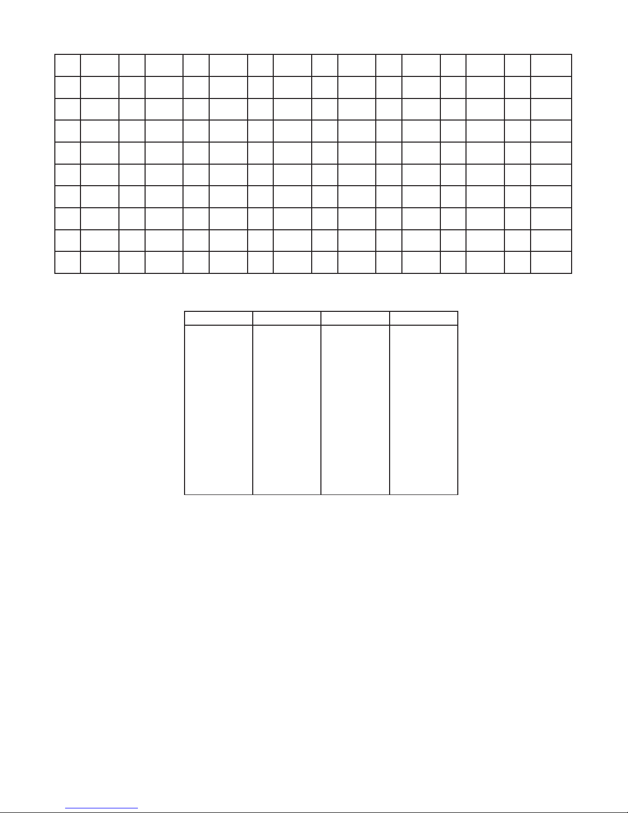
0 °C 10 mils 20 in/s 30 kHz 40 MPa 50 GW 60 mV 70 gal/h
1 °F 11 yd 21 ips 31 Hz 41 kPa 51 MW 61 W71 t/h
2 K 12 m322 ft/s 32 p/min 42 hPa 52 kW 62 S 72 mol
3 % 13 L 23 in/min 33 p/h 43 bar 53 hp 63 µS 73 pH
4 m 14 s 24 ft/min 34 p/day 44 mbar 54 A 64 m3/min 74 [blank]
5 cm 15 min 25 in/h 35 t 45 kJ 55 kA 65 m3/h
6 mm 16 m/s 26 ft/h 36 kg 46 Wh 56 mA 66 l/s
7 µm 17 mm/s 27 m/s237 g 47 MWh 57 µA 67 l/min
8 Ft 18 m/min 28 mm/s238 N 48 kWh 58 V 68 l/h
9 in 19 m/h 29 rpm 39 Pa 49 W 59 kV 69 gal/min
Table 1: Display units

4222MCM101 5
4222 Process Parameter List
Parameter
Name No. Register
Address
Register
Size
Read/
Write Type Description Values
DISPLAY VALUE 0 1000 2 RO INTEGER
The measured value in 1/10 of °C/°F for
temperature Input types, or the scaled
display value for non-temperature input types
(INTEGER version of PRIMARY VALUE)
Range for non-temperature input types:
DISPLAY LOW...DISPLAY HIGH
Range for temperature input types: equals
the measurement range for the
selected sensor type
PERCENT PV 1 1002 1 RO INTEGER
The relative input value as 1/100 of %
calculated from PRIMARY VALUE.
For temperature input types 0...100%
corresponds the selected temperature range
(OUTPUT LOW...OUTPUT HIGH)
For non-temperature input types 0...100%
corresponds the selected fixed range
(e.g. 4...20 mA)
Range: 0...9999
(e.g. 7898 = 78.98%)
MEASURE
STATUS 2 1003 1 RO INTEGER The actual measurement status
OUTPUT UNDERRANGE: bit 0=1
OUTPUT OVERRANGE: bit 1=
1
OUTPUT LOW LINITED: bit 2=
1
OUTPUT HIGH LIMITED: bit 3=
1
INPUT UNDERRANGE: bit 4=
1
INPUT OVERRANGE: bit 5=
1
SENSOR SHORTED: bit 6=
1
SENSOR BROKEN: bit 7=
1
ERROR STATUS 3 1004 1 RO INTEGER The actual error status (Device errors)
AD COMM. ERROR bit 0=
1
CJC ERROR bit 1=
1
RAM ERROR bit 2=
1
EEP ERROR bit 3=
1
FLASH ERROR bit 4=
1
NOT CALIBRATED bit 5=
1
BAD OUTPUT bit 6=
1
NO OUTPUT bit 7=
1
OUTPUT SUPPLY ERROR bit 8=
1
INPUT SUPPLY ERROR bit 9=
1
PRIMARY RAW
VALUE 5 1005 2 RO FLOAT
The measured value in 1/10 of °C/°F for
temperature Input types, or the scaled
display value for non-temperature input types,
NOT PROCESS CALIBRATED.
Range for non-temperature input types:
DISPLAY LOW...DISPLAY HIGH
Range for temperature input types equals
the measurement range for the selected
sensor type
PRIMARY VALUE 6 1007 2 R/W FLOAT
The measured value in 1/10 of °C/°F for
temperature Input types, or the scaled display
value for non-temperature input types
Range for non-temperature input types:
DISPLAY LOW...DISPLAY HIGH
Range for temperature input types equals
the measurement range for the selected
sensor type
RELATIVE PV 7 1009 2 RO FLOAT
The relative input value calculated
from PRIMARY VALUE.
For temperature input types relative to
selected temperature range
(OUTPUT LOW...OUTPUT HIGH)
For non-temperarure input types relative to
selected fixed range (e.g. 4...20 mA)
Range: 0.0...1.0
OUTPUT
FREQUENCY 8 1011 2 R/W FLOAT Calculated output value in mHz or 1/1000nds
of pulses per min./hour/day
Range with frequency selected:
0...25000000 (0...25000 Hz)
Range with pulse selected:
0...30000000
MEASURE
CONTROL 9 1013 1 R/W INTEGER
Measurement control.
By disabling update of certain READ/WRITE
parameters PRIMARY VALUE, OUTPUT VALUE or
RELAY STATUS, these can be simulated
by writing values.
All bits are cleared when
TIMEOUT COUNTER reaches 0
RESTART SCAN bit 0 = 1
RESTART WITH
NEW CONFIGURATION bit 1 = 1
DISABLE PRIMARY
VALUE UPDATE bit 2 = 1
DISABLE OUTPUT
VALUE UPDATE bit 3 = 1
NOT USED bit 4 = 1
DISABLE
CONFIGURATION CHECK bit 5 = 1
GET NEW
CONFIGURATION bit 6 = 1
TIMEOUT
COUNTER 10 1014 1 R/W INTEGER
Time out counter,
decrements every 0.075 second.
When reaching 0 (if not refreshed) all bits in
MEASURE CONTROL will be cleared.
Range: 0...255
INTERNAL
TEMPERATURE 11 1015 1 RO INTEGER Internal measured or connector temperature
in 1/10 of °C/°F
Range:
-200...800 (-20.0...80.0 °C) or
-40...1760 (-4.0...176.0 °F)

6 4222MCM101
4511 Modbus Configuration Parameter List
Parameter
Name No. Register
Address
Register
Size
Read/
Write Type Description Values
ENABLE MODBUS 1 3000 1 R/W INTEGER
Enable Modbus communication.
If disabled, 4511 ignores all frames sent
from the Modbus master and the only way to
re-enable Modbus communication is by using the
4511 menu.
NO = 0
YES = 1
BAUDRATE 2 3001 1 R/W INTEGER The baud value used for
Modbus communication
2400 BAUD = 0
4800 BAUD = 1
9600 BAUD = 2
19200 BAUD = 3
38400 BAUD = 4
57600 BAUD = 5
115200 BAUD = 6
ENABLE
AUTOBAUD 3 3002 1 R/W INTEGER
Enable automatic baudrate detection.
If enabled, 4511 determines the baudrate
automatically by listening to frames sent
on the Modbus line.
NO = 0
YES = 1
PARITY 4 3003 1 R/W INTEGER Configures parity check on Modbus frames
NONE = 0
EVEN PARITY = 1
ODD PARITY = 2
STOPBITS 5 3004 1 R/W INTEGER Configures the number of stopbits in Modbus
frames
ONE STOPBIT = 1
TWO STOPBITS = 2
ADDRESS 6 3005 1 R/W INTEGER Configures the Modbus address of the 4511
(Address 0 is broadcast address) Range: 1...247
RESPONSE
DELAY 7 3006 1 R/W INTEGER Configures minimum delay for Modbus
response in ms Range: 0...1000
4511 Modbus Status Parameter List
Parameter
Name No. Register
Address
Register
Size
Read/
Write Type Description Values
AUTOBAUD
STATUS 1 4000 1 RO INTEGER Actual state of automatic baudrate detection
2400 BAUD = 0
4800 BAUD = 1
9600 BAUD = 2
19200 BAUD = 3
38400 BAUD = 4
57600 BAUD = 5
115200 BAUD = 6
SEARCHING = 7
ERROR = 8
IDENTIFY DEVICE 2 4001 1 R/W INTEGER
Enables the device to flash the LCD
background with appr. 4 Hz.
Value will automatically return to NO if
not written within 10 seconds!
NO = 0
YES = 1
MAXIMUM READ
REGISTERS 3 4002 1 RO INTEGER
Maximum allowed number of registers
that can be read in one command, with
the given/detected baudrate
Range: 8...32
4511 Additional Parameter List
Parameter
Name: Nr. Register
Address:
Register
Size:
Read/
Write: Type: Description: Values
ROTATE DEVICE 1 3100 1 R/W INTEGER
Enables the display and key buttons to be used
normally when the host device is mounted
upside down
NO = 0
YES = 1
4222MCM101 7
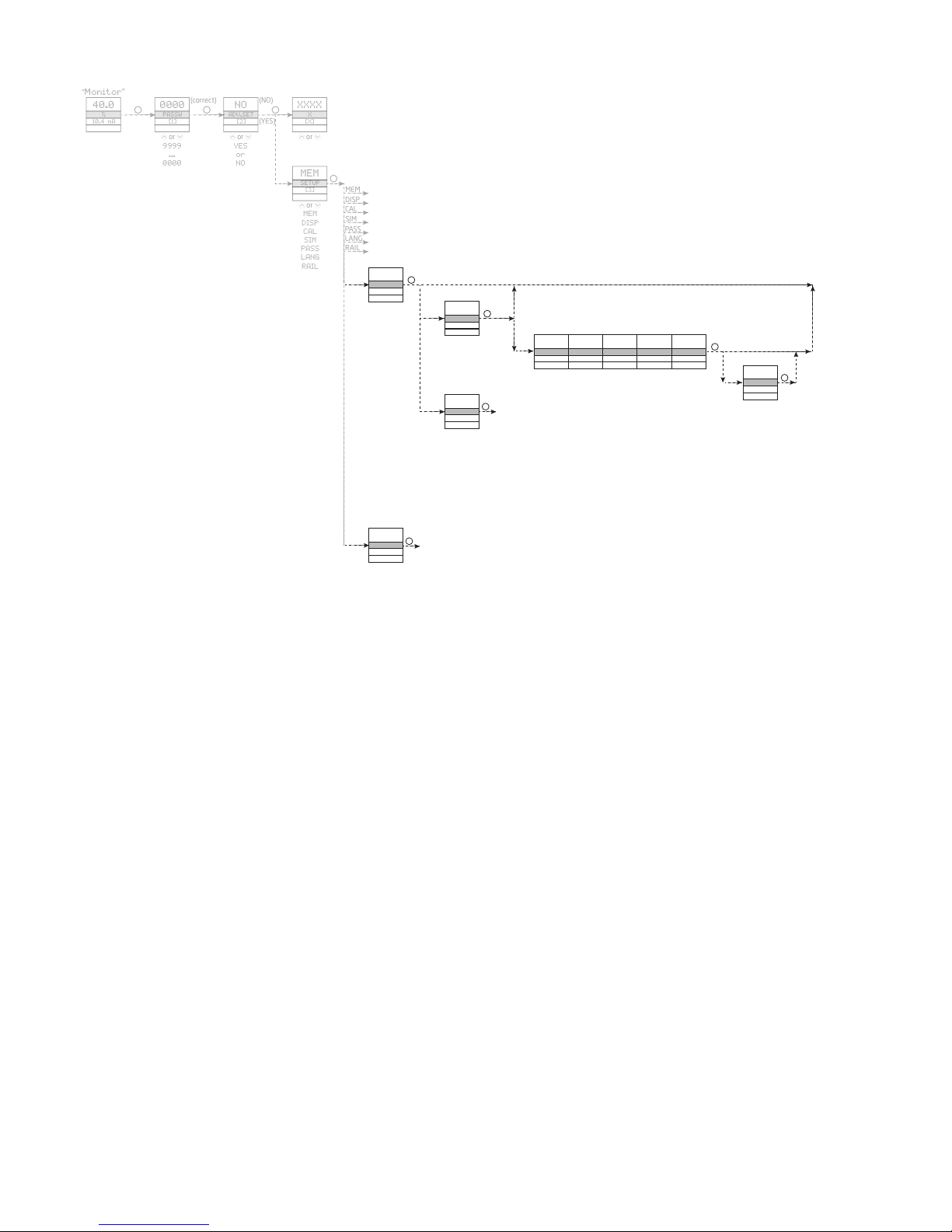
4511 Modbus Front Programming Parameter Menu
"
M
"
or
or
(correct)
(NO)
or
(YES)
or
MEM
DISP
CAL
SIM
PASS
LANG
MODB
or
(OFF)
(ON) MODB
or
(YES)
(NO)
"M"
"M"
or
or
or
or
or
(YES)
(NO)
or
"M"
*1)
RAIL
MODB
ORIEN
*1)
ORIEN
or
Please note:
If no keys are activated for 1 minute, the 4511 display will return to the “Monitor” view without saving.
The display will aslo return to "Monitor" upon successful Modbus write command!
The grayed-out menus and texts are only shown for guidance and are not a part of the 4511 specific submenu.
The Modbus submenu is located in the Advanced Setting menu structure of any host device using the 4511.
The actual placement is defined for each particular device.
Scrolling HELP TEXTS:
[1] Set correct password
[2] Enter advanced setup menu
[3] Perform memory operations
Enter display setup
Perform process calibration
Enter simulation setup
Enter password setup
Enter language setup
Enter rail setup (System 9000)
Enter Modbus setup
[4] Check automatic baudrate detection status
Enable Modbus communication
Disable Modbus communication
[5] Reset Modbus to default
[6] Select Modbus slave address
[7] Select parity for Modbus
[8] Select number of stop bits
[9] Select response delay in ms
[10] Enable automatic baudrate detection
[11] Searching for Modbus baudrate
Modbus baudrate detected
Modbus baudrate not detected
[12] Select baudrate in bps
[13] Rotate device upside down?
* 1) Only if automatic
baudrate detection
is enabled
Other manuals for PREASY 4222
2
This manual suits for next models
1
Table of contents
Other PR Media Converter manuals


Popular Media Converter manuals by other brands


Schumacher Electric
Schumacher Electric BATTERY EXTENDER BE01256 owner's manual

Gefen
Gefen Home Theater Scaler user manual

TDK-Lambda
TDK-Lambda EZA2500 Series Quick Manual/Basic

resi-linx
resi-linx digi-MOD HD-4002DM User Guide and Install Manual

golmar
golmar CD-PLUS/90 instruction manual

Televes
Televes 585401 quick start guide