PR 4104 User manual

4104
SIGNALS THE BEST
PENDING
Universal Signal
Transmitter
No. 4104V100-UK
From ser. no 121479001

(1240)
PR electronics A/S tilbyder et bredt program af analoge og digitale
signalbehandlingsmoduler til industriel automation. Programmet
består af Isolatorer, Displays, Ex-barrierer, Temperaturtransmittere,
Universaltransmittere m. Vi har modulerne, du kan stole på i selv
barske miljøer med elektrisk støj, vibrationer og temperaturud-
sving, og alle produkter opfylder de strengeste internationale stan-
darder. Vores motto »Signals the Best« er indbegrebet af denne
loso – og din garanti for kvalitet.
PR electronics A/S offers a wide range of analogue and digital
signal conditioning devices for industrial automation. The product
range includes Isolators, Displays, I.S. Interfaces, Temperature
Transmitters, and Universal Devices. You can trust our products
in the most extreme environments with electrical noise, vibrations
and temperature uctuations, and all products comply with the
most exacting international standards. »Signals the Best« is the
epitome of our philosophy – and your guarantee for quality.
PR electronics A/S offre une large gamme de produits pour le
traitement des signaux analogiques et numériques dans tous
les domaines industriels. La gamme de produits s’étend des
transmetteurs de température aux afcheurs, des isolateurs aux
interfaces SI, jusqu’aux modules universels. Vous pouvez compter
sur nos produits même dans les conditions d’utilisation sévères,
p.ex. bruit électrique, vibrations et uctuations de température.
Tous nos produits sont conformes aux normes internationales les
plus strictes. Notre devise »SIGNALS the BEST« c’est notre ligne
de conduite - et pour vous l’assurance de la meilleure qualité.
PR electronics A/S verfügt über ein breites Produktprogramm
an analogen und digitalen Signalverarbeitungsmodule für die in-
dustrielle Automatisierung. Dieses Programm umfasst Displays,
Temperaturtransmitter, Ex- und galvanische Signaltrenner, und
Universalgeräte. Sie können unsere Geräte auch unter extremen
Einsatzbedingungen wie elektrisches Rauschen, Erschütterungen
und Temperaturschwingungen vertrauen, und alle Produkte von
PR electronics werden in Übereinstimmung mit den strengsten
internationalen Normen produziert. »Signals the Best« ist Ihre
Garantie für Qualität!
DK
UK
FR
DE

4104V100-UK 1
UNIVERSAL SIGNAL TRANSMITTER
4104
CONTENTS
Warning .......................................................................................... 2
Safety instructions.......................................................................... 3
EC declaration of conformity ......................................................... 4
How to demount system 4000....................................................... 5
When front LED flashes red / 4501 display shows AO.ER............ 5
Applications.................................................................................... 6
Technical characteristics................................................................ 6
Mounting / installation.................................................................... 7
PR 4501 Display / programming front ........................................... 8
Connections ................................................................................... 9
Order codes ................................................................................... 10
Specifications................................................................................. 10
4501 display readout of input 4-20 mA loop error detection
and signal ”outside range” ........................................................ 14
Block diagram ................................................................................ 15
Configuration / operating the function keys .................................. 16
Routing diagram............................................................................. 17
Routing diagram, Advanced settings (ADV.SET)............................ 19
Scrolling help text in display line 3 ................................................ 21
2 4104V100-UK
SYMBOL IDENTIFICATION
Triangle with an exclamation mark: Read the manual before
installation and commissioning of the device in order to avoid
incidents that could lead to personal injury or mechanical damage.
The CE mark proves the compliance of the device with the
essential requirements of the directives.
The double insulation symbol shows that the device
is protected by double or reinforced insulation.
WARNING
This device is designed for connection to hazardous electric
voltages. Ignoring this warning can result in severe personal injury
or mechanical damage.
To avoid the risk of electric shock and re, the safety instructions
of this guide must be observed and the guidelines followed. The
specications must not be exceeded, and the device must only
be applied as described in the following.
Prior to the commissioning of the device, this installation guide
must be examined carefully.
Only qualied personnel (technicians) should install this device.
If the equipment is used in a manner not specied by the
manufacturer, the protection provided by the equipment may be
impaired.
WARNING
Until the device is xed, do not connect hazardous voltages to
the device. The following operations should only be carried out
on a disconnected device and under ESD safe conditions:
General mounting, connection and disconnection of wires.
Troubleshooting the device.
Repair of the device must be done by PR electronics A/S only.
WARNING
Do not open the front plate of the device as this will cause
damage to the connector for the display / programming front PR
4501. This device contains no DIP-switches or jumpers.
SYSTEM 4000 must be mounted on a DIN rail according to DIN
EN 60715.
GENERAL
HAZARD-
OUS
VOLTAGE
CAUTION

4104V100-UK 3
SAFETY INSTRUCTIONS
RECEIPT AND UNPACKING
Unpack the device without damaging it. The packing should always follow the
device until this has been permanently mounted. Check at the receipt of the
device whether the type corresponds to the one ordered.
ENVIRONMENT
Avoid direct sunlight, dust, high temperatures, mechanical vibrations and shock,
as well as rain and heavy moisture. If necessary, heating in excess of the stated
limits for ambient temperatures should be avoided by way of ventilation.
Installation Category II, Pollution Degree 2, and Insulation Class II.
The module is designed to be safe at least under an altitude up to 2 000 m.
MOUNTING
Only qualied technicians who are familiar with the technical terms, warnings,
and instructions in this installation guide and who are able to follow these should
connect the device.
Should there be any doubt as to the correct handling of the device, please contact
your local distributor or, alternatively, PR electronics A/S.
Mounting and connection of the device should comply with national
legislation for mounting of electric materials, i.e. wire cross section,
protective fuse, and location. Descriptions of input / output and supply
connections are shown in this installation guide and on the side label.
The following apply to xed hazardous voltages-connected devices:
The max. protective fuse is 10 A. A power switch shall be easily accessible and
close to the device. The power switch shall be marked as the disconnecting unit
for the device.
UL installation
Use 60/75°C copper conducters only.
For use only in pollution degree 2 or better.
Max. ambient temperature..........................60°C
Max. wire size.............................................. AWG 26-14
UL file number............................................. E231911
Calibration and adjustment
During calibration and adjustment, the measuring and connection of external
voltages must be carried out according to the specications of this installation
guide. The technician must use tools and instruments that are safe to use.
Cleaning
When disconnected, the device may be cleaned with a cloth moistened with
distilled water.

4 4104V100-UK
EC DECLARATION OF CONFORMITY
As manufacturer
PR electronics A/S
Lerbakken 10
DK-8410 Rønde
hereby declares that the following product:
Type: 4104
Name: Universal signal transmitter
is in conformity with the following directives and standards:
The EMC Directive 2004/108/EC and later amendments
EN 61326-1
For specification of the acceptable EMC performance level, refer to the electrical
specifications for the module.
The Low Voltage Directive 2006/95/EC and later amendments
EN 61010-1
Rønde, 1 October 2012 Kim Rasmussen
Manufacturer’s signature

4104V100-UK 5
HOW TO DEMOUNT SYSTEM 4000
Picture 1:
Detach the device from the DIN rail by lifting the bottom lock.
When front LED flashes red / 4501 display shows AO.ER
PR 4104 is designed as a device with a high safety level. Therefore, a continuous
measurement of the outgoing current is carried out on a 4...20 mA output signal.
If the analogue output current is 0 mA (can e.g. be caused by an open output
loop), an error mode switches on the red front LED and the 4501 display shows
AO.ER. This function is not a default option but must be actively selected in the
menu by programming the analogue output to S4-20. The error mode can only
be reset by switching off and then switching on the supply voltage to the device.

6 4104V100-UK
UNIVERSAL SIGNAL TRANSMITTER
4104
• Input and output of uni-/bipolar voltage and current signals
for isolation and conversion applications
• Handles both active and passive signals on input and output
• Fully programmable and live process signal monitoring
via 4501 display
• Fast response time < 20 ms and excellent conversion
accuracy < 0.05% of selected range
• Universal supply voltage, 21.6…253 VAC / 19.2...300 VDC
Applications
• The 4104 is a unique signal isolator and converter for unipolar and bipolar
voltage and current signals.
• The unit combines digital and analogues techniques in signal conversion
applications and is ideal for galvanic signal separation and measurement of
floating signals.
• Process control is possible using the unipolar/bipolar analogue voltage and
current output.
• The analogue output can be set to either active current or passive 2-wire
output.
• The analogue output signal is linear and selectable as direct or inverted but
can also be set to ”V” curve function, 100 - 0 - 100% on the basis of a linear
0 - 100% input signal.
Technical characteristics
• Allprogrammingiscarriedoutusingthedetachable4501displaywhichcan
additionally monitor and indicate operation status of the process signal.
• The 4104 input offers auxiliary supply for both 2-wire (>16 V) and 3-wire
transmitters(>18V).
• The unit has a very fast signal response time < 20 ms combined with an
excellent conversion accuracy of better than 0.05% of selected range.
• Theanalogueoutputsignalcanbedampedfrom0.0…60.0sandadditionally
has a very high load capability of up to 800 ohm.

4104V100-UK 7
• Meeting the NAMUR NE21 recommendations, the 4104 ensures top
measurement performance in harsh EMC environments. Additionally, the 4104
meets NAMUR NE43 recommendations.
• High3-port2.3kVACgalvanicisolationandanexcellentsignal/noiseratio>60
dB.
Mounting / installation
• AverylowpowerconsumptionallowsfortightDINrailmountinginSafearea
or in Zone 2 / Cl. 1 Div. 2.
• Approvedformarineapplications.
• Programming,signalmonitoringanda2-pointprocesscalibrationispossible
via the 4501 detachable display.
• Allprogrammingcanbeprotectedbyauserpassword.

8 4104V100-UK
PR 4501 DISPLAY / PROGRAMMING FRONT
Functionality
The simple and easily understandable PReasy menu
structure and the explanatory help texts guide you
effortlessly and automatically through the configuration
steps, thus making the product very easy to use. Functions
and configuration options are described in the section
”Configuration / operating the function keys”.
Mounting / installation
• 4501 is a detachable display that can be mounted on the 4104 front for
programming and signal monitoring.
Application
• Communicationsinterfaceformodificationofoperationalparametersin4104.
• Whenmountedintheprocess,thedisplayshowsprocessvaluesanddevice
status.
Technical characteristics
• LCDdisplaywith4lines:Line1(H=5.57mm)showsthescaledprocessvalue
-OK or error.Line2(H=3.33 mm) shows the selectedengineeringunit.Line
3 (H=3.33 mm) shows analogue output or TAG no. Line 4 shows status for
communication and signal trending.
• Programming access can be blocked by assigning a password. 4501 can be
moved from one device to another. The configuration of the first transmitter can
be saved and downloaded to subsequent transmitters.

+
33
32
31
44
43
42
41
(±)
12
14
13
11
10 V
1 V
10 V
1 V
(±)
}
(±)
+
++
+
+
+
+
4104V100-UK 9
CONNECTIONS
Input signals:
Output signals:
Supply:
21.6...253 VAC
or
19.2...300 VDC
Current 3-wire Tx2-wire Tx Voltage
+ V supply
Safe Area or
Zone 2 / Cl. 1, Div. 2, gr. A-D
Current & voltage 2-wire

10 4104V100-UK
Order codes
4104 = Universal signal transmitter
4501 = Display / programming front
Specifications
Environmental conditions:
Specifications range.................................... -20°C to +60°C
Storage temperature ................................... -20°C to +85°C
Calibration temperature............................... 20...28°C
Relative humidity......................................... <95%RH(non-cond.)
Protection degree........................................ IP20
Installation in pollution degree 2 & measurement / overvoltage category II.
Mechanical specifications:
Dimensions (HxWxD)................................... 109 x 23.5 x 104 mm
Dimensions (HxWxD) w/ 4501 display........ 109 x 23.5 x 116 mm
Weight approx. ............................................ 250 g
DIN rail type................................................. DIN EN 60715 - 35 mm
Wire size...................................................... 0.13...2.08 mm2/
AWG 26...14 stranded wire
Screw terminal torque ................................. 0.5 Nm
Common electrical specifications:
Supply voltage, universal ............................ 21.6...253 VAC, 50...60 Hz
or 19.2...300 VDC
Power consumption .................................... ≤ 2.5 W
Internal power dissipation........................... ≤ 2.0 W
Isolation voltage - test / working ................ 2.3 kVAC / 250 VAC
MTBF, acc. to IEC 61709 (SN29500) .......... >111years
Signal / noise ratio ...................................... >60dB
Cut-off frequency (3 dB).............................. >40Hz
Response time (0...90%, 100...10%) .......... <20ms

4104V100-UK 11
ofspan=ofselectedrange
Input specifications:
Current input:
Signal range ................................................ ±23 mA
Programmable measurement ranges.......... 0-20, 4-20, ±10, ±20 mA
Input voltage drop, nom.............................. 1.4 V @ 20 mA
Loop error detection, 4...20 mA:
Low detection ........................................ <3.6mA
High detection ........................................ >21mA
2-wire loop supply, (terminal 43 & 44)......... >16V/20mA
3-wire loop supply, (terminal 42 & 44)......... >18V/20mA
Loop supply limitation, terminal 44, nom.... 30 mA
Voltage input:
Signal range ................................................ ±12 V
Programmable measurement ranges.......... 0-1, 0.2-1, 0-5, 1-5, 0-10, 2-10 V,
±1, ±5 and ±10V
Input resistance, nom.................................. 2 MΩ
Current output specifications:
Active unipolar and bipolar mA:
Programmable ranges................................. 0-20, 4-20, ±10 and ±20 mA
Direct or Inverted action
V-curve function, 100-0-100%.................... 20-0-20 mA
Load, max. .................................................. 800 Ω / ± 16 V @ ±20 mA
Accuracy values
Input
Absolute
accuracy
Temperature
coefficient
All ≤±0.05% of span ≤±0.01% of span / °C
EMC immunity influence ............................................... <±0.5%ofspan
Extended EMC immunity:
NAMUR NE 21, A criterion, burst ................................. <±1%ofspan

12 4104V100-UK
Passive 2-wire mA:
Programmable ranges................................. 0-20 and 4-20 mA
Direct or Inverted action
V-curve function, 100-0-100% ................... 20-0-20 mA
External 2-wire loop supply ....................... 3.5 - 26 V
Common specifications current output:
Signal range ................................................ 0...23 mA (unipolar) /
-23...+23 mA (bipolar)
Current limit................................................. ≤ 28 mA (unipolar) /
±28 mA (bipolar)
Load stability............................................... ≤ 0.005% of span / 100 Ω
Programmable damping.............................. 0.0...60.0 s
Output limitation at outside range:
on 4...20 and 20...4 mA signals .............. 3.8...20.5 mA
on other unipolar signals......................... 0 and 115% of max. value
on bipolar signals.................................... ±115% of min. and max. values
Sensor error indication, at 4...20 mA input:
selectable ................................................ Low, High, Zero or None
Low - corresponds to 0 mA at 0...20 mA and to 3.5 mA at 4...20 mA
High - corresponds to 23 mA at both 0...20 and 4...20 mA
Zero - equals 0 mA output
None - the output state is undefined
Voltage output specifications:
Programmable ranges................................. 0/0.2-1, 0/1-5, 0/2-10, ±1, ±5 and
±10 V - Direct or Inverted action
V-curve function, 100-0-100% ................... 1-0-1 V, 5-0-5 V and 10-0-10 V
Load, min .................................................... >500kΩ
Programmable damping.............................. 0.0...60.0 s
Output limitation at outside range:
on unipolar signals starting from 0 ......... 0 and 115% of max. value
on unipolar signals with offset ................ -5% of min. value and
115% of max. value
on bipolar signals.................................... ±115% of min. and max. values
Sensor error indication, at 4...20 mA input:
selectable ................................................ Low, High, Zero or None
Low - corresponds to the selected min range value
High - corresponds to the selected max range value
Zero - equals 0 V output
None - the output state is undefined

4104V100-UK 13
Approvals:
EMC 2004/108/EC ...................................... EN 61326-1
LVD 2006/95/EC.......................................... EN 61010-1
UL, Standard for Safety .............................. UL 508
GOST R
Marine:
Det Norske Veritas, Ships & Offshore ......... Pending
Ex:
FM ............................................................... 3025177

14 4104V100-UK
4501 display readout of input 4-20 mA loop error detection and
signal ”outside range”
Input loop error check:
Device: Configuration Input loop error detection
4104 OUT.ERR=NONE. OFF
OUT.ERR=DOWN,UPandZERO ON
Input ”outside range” limits - readout (IN.LO, IN.HI):
Input Ranges Readout Limit
CURR All - unipolar and bipolar IN.LO <-23mA
IN.HI >23mA
VOLT All - unipolar and bipolar IN.LO <-12V
IN.HI >12V
Input loop error detection - readout (LO.ER):
Input Range Readout Limit
CURR 4..20 mA LO.ER <=3.6mA;>=21mA
Display readout below min.- / above max. (-1999, 9999):
Input Range Readout Limit
All All -1999 Displayreadout<-1999
9999 Displayreadout>9999
Readout at hardware error
Error search Readout Error caused by
Check measurement of analogue output - read *note AO.ER No load on the current output
(only S4...20 mA)
Communications test 4501 / 4104 NO.CO Connection error
Hardware error - read ** note FL.ER Error in FLASH
Configuration error - read ** note CO.ER Error in FLASH
Check that saved configuration in 4501 matches device TY.ER Invalid type or rev. no
Hardware error - read *note AO.SU Analogue output supply err.
Hardware error - read *note RA.ER RAM error
Hardware error - read *note EE.ER EEPROM error
Hardware error - read *note AD.ER A/D converter error
Hardware error - read *note IF.ER Flash check sum error
! All error indications flash (1 Hz), and the corresponding helptext is shown.
If the error is an input loop error, the display backlight flashes as well - this is
acknowledged (stopped) by pushing the OK button.
* Error is acknowledged by either stepping through the basic setup, or by
resetting the device power.
Some types of errors can only be acknowledged by resetting the device power.
** Error is acknowledged by stepping through the basic setup.
4104V100-UK 15
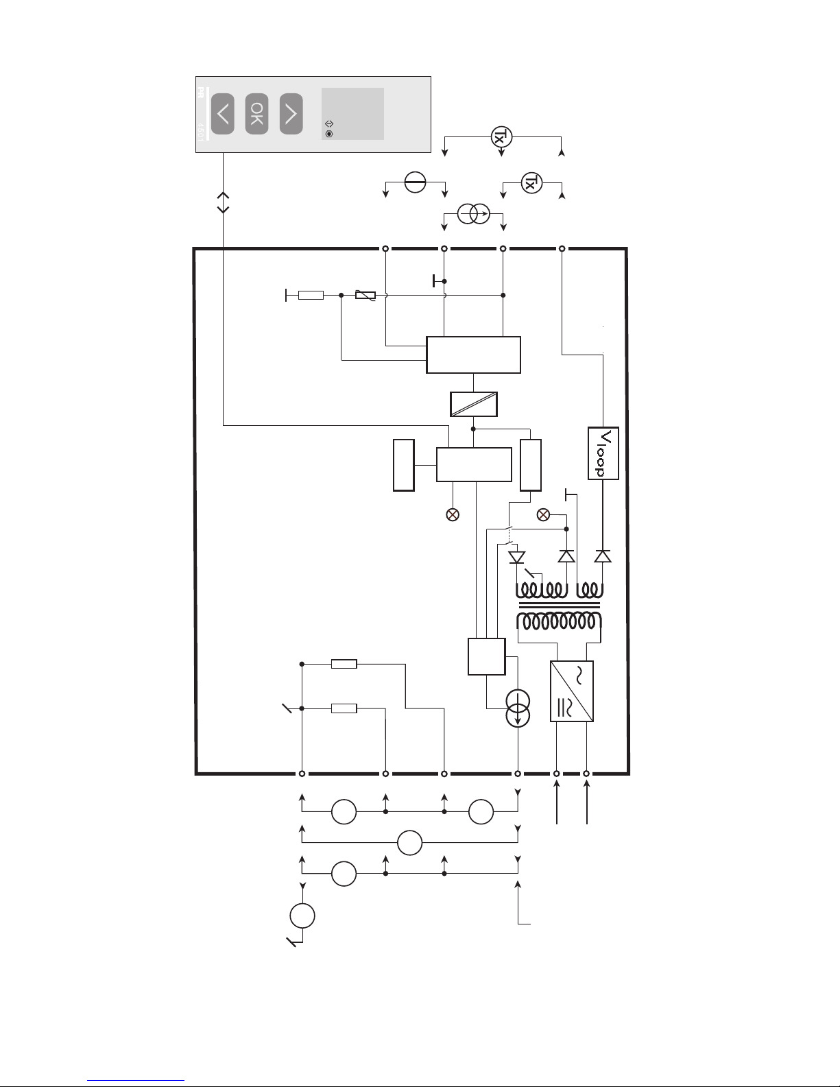
BLOCK DIAGRAM
500 Ω
EEPROM
D /A
11
13
14
50Ω
33
31
12
PT C
43
44
42
41
20 Ω
A/D
+
-
+
-
V
V
mA
mA
I+
10 V
1 V
4104
Gnd.
I + V I V
HW
Watchdog
CPU
-
+
mA -
0.
3-wire Tx
2-wire TxVoltage
Current
21.6...253 VAC or
19.2...300 VDC
+Vsupply
2-wire
Green
Red

16 4104V100-UK
CONFIGURATION /
OPERATING THE FUNCTION KEYS
Documentation for routing diagram.
In general
When configuring the 4104, you will be guided through all parameters and you
can choose the settings which fit the application. For each menu there is a
scrolling help text which is automatically shown in line 3 on the display.
Configuration is carried out by use of the 3 function keys:
1 will increase the numerical value or choose the next parameter
2will decrease the numerical value or choose the previous parameter
3will accept the chosen value and proceed to the next menu
When configuration is completed, the display will return to the default state 1.0.
Pressing and holding 3will return to the previous menu or return to the default
state (1.0) without saving the changed values or parameters.
If no key is activated for 1 minute, the display will return to the default state (1.0)
without saving the changed values or parameters.
Further explanations
Password protection: Programming access can be blocked by assigning a
password. The password is saved in the transmitter in order to ensure a high
degree of protection against unauthorised modifications to the configuration.
Default password 2008 allows access to all configuration menus.
Signal and loop error info via display front 4501
Input loop error at 4-20 mA signal is displayed as LO.ER (see table page 14).
Input signals outside the selected range are displayed as IN.LO indicating
low input signal or IN.HI indicating high input signal. (see table page 14).
Error indication is displayed in line 1 as text and at the same time the backlight
flashes. A flashing bullet in line 4 is indicating correct functioning of 4501.
Signal and sensor error indication without display front
Status of the unit can also be read from the red/green LED in the front of the device.
Green flashing LED 13 Hz indicates normal operation.
Green flashing LED 1 Hz indicates loop error.
Steady green LED indicates internal error.
Steady red LED indicates fatal error.

Power up
1 2
0000
PASSW.
Txt 1
50.0
%
12.0
3
3
0000
9999
1 2
NO
ADV.SET
Txt 2
NO
YES
1 2
3VOLT
IN TYPE
Txt 3
VOLT
CURR
1 2
30-10
V.RANGE
Txt 5
-/+10
-/+5
-/+1
2-10
0-10
1-5
0-5
0.2-1
0-1
3
CURR
IN TYPE
Txt 3
34-20
I.RANGE
Txt 4
-/+20
-/+10
0-20
4-20
1 2
3
YES
ADV.SET
Txt 2
3
0.00
DISP.LO
Txt 8
99.99
-19.99
1 2
11.11
DEC.P
Txt 7
1.111
11.11
111.1
1111
1 2
3
UNIT
V
Txt 6
V
mA
%
(69 units)
1 2
3
1.0
@C
@F
%
A
bar
cm
ft
ft/h
ft/min
ft/s
g
gal/h
gal/min
GW
hp
hPa
Hz
in
in/h
in/min
in/s
ips
K
kA
kg
kJ
kPa
kV
kW
kWh
l
l/h
l/min
l/s
m
m/h
m/min
m/s
m/s2
m3
m3/h
m3/min
mA
mbar
mils
min
mm
mm/s
mol
MPa
mV
MW
MWh
N
Ohm
Pa
pH
rpm
s
S
t
t/h
uA
um
uS
V
W
Wh
yd
[blank]
1 2
4104V100-UK 17
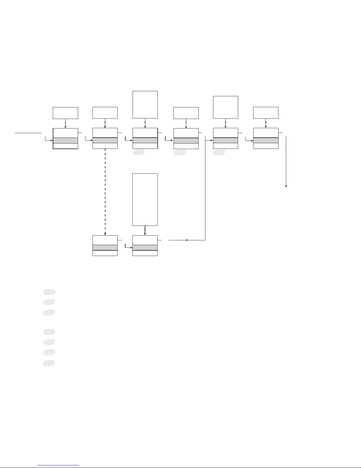
1.0= Defaultstate
Line 1 shows input signal.
Line 2 shows UNIT.
By pressing 1and
2simultaneously line 3
alternates between
A.Out and TAG.
Line 4 shows trending in
the process signal and
communication status.
Continued on the page
Routing diagram ADV.SET
Selectable UNITS:
*1
ROUTING DIAGRAM
If no key is activated for 1 minute, the display will return to the
default state 1.0 without saving configuration changes.
1Increase value / choose next parameter
2Decrease value / choose previous parameter
3Accept the chosen value and proceed to the next menu
Hold 3Back to previous menu / return to menu 1.0 without saving
Continued on the next page
10.00
DISP.HI
Txt 9
99.99
-19.99
1 2
*3 *2 *4
CURR
ANA.OUT
Txt 10
VOLT
CURR
1 2
3ACTI
OUT.MOD
Txt 13
-/+20
-/+10
S4-20
4-20
0-20
VOLT
ANA.OUT
Txt 10
30-10
O.RANGE
Txt 12
-/+10
-/+5
-/+1
2-10
0-10
1-5
0-5
0.2-1
0-1
1 2
3
4-20
O.RANGE
Txt 11
1 2
3UP
OUT.ERR
Txt 14
ZERO
UP
DOWN
NONE
1 2
3
1 2
PASS
ACTI
30.0
RESP
Txt 15
60.0
0.0
1 2
3
3
3
18 4104V100-UK
To default state 1.0
Menu only displayed if password is enabled. (E.PAS = YES)
*1
Menu not displayed if a Bipolar Output Range is selected.
Direct or Inverted output characteristics must be set in the ADV setting OFUN menu.
OnlyrangesstartingatzeroareavailableforOFUN=V.FUNC-referto*7.
Menu only displayed if input type supports sensor error check.
Selectable range as defined by DEC.P, DISP.LO and DISP.HI.
VFUN (V-shaped output function) is only available when
an output range starting at zero is selected.
DIR (direct) and INV (inverted) output characteristics can be
combined with all selectable output ranges.
Selectable range equals selected input range.
*2
*4
*3
*5
*7
*6
Table of contents
Other PR Transmitter manuals


Popular Transmitter manuals by other brands


Evikon
Evikon E2615-CO user manual

Magenta
Magenta MultiView II DVI-TX quick start guide

Emerson
Emerson Rosemount Oxymitter 4000 Reference manual

Extron electronics
Extron electronics DTP2 T 201 D Series Setup guide

Emerson
Emerson Rosemount 3051S Series quick start guide

Burkert
Burkert 8312 Series operating manual


